
Step 1:
It is a robot that relies on calculations to position servos and pre-programmed sequences of legs.
I'm doing this by handmade way is because of it could be fun and educational for 3D design/printing and robot control.
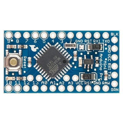
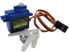
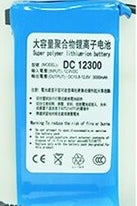
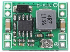
Step 1: Electrics Parts Preparation
Step 2: Make the Main-board


6 More Images
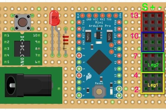
Refer to the schematics file, and place all components like the pictures. you can make the board as small as passable.
The main-board that the last one picture is the newest version, just for you reference.
Here are some tips while you are going to building the PCB:
1. Be sure the output voltage of DC-DC module should be 5v before mount to the perfboard.
2. The servos consume a lot of power, almost 3A in full loading condition. Please use more thick wire for "power" and ground" traces.
3. Do the "open/short" test with the multi-meter for your PCB when you finish the soldering, that is the important process.
4. Using the female pin header instead of solder the modules(Arduino, DC-DC) on the perfboard directly
5. The LED will be on while the "Switch" turns off. Why I design this way is because I would like to check the power source is ok or not when I plug in the power source like battery or something else, it is a simple way for protection..
6. While you see the LED turns on after connect the 12v battery to the board, congratulation!
Attachments
Step 3: Test the Main-board
Test process:
1. Don't plug the DC-DC and Arduino Pro Mini into the main-board
2. connect the battery to the 12v-Jack of main-board
3. Check the LED, if LED turns on, that is a good start.
4. Push the POWER-Switch, the LED should be off.
4. Using the multi-meter to check all of +5V and GND pins are correct
5. Push the POWER-Switch back to turn off the power, the LED turns on
6. Plug the DC-DC and Arduino Pro Mini into the main-board
7. Push the POWER-Switch, the LED turns off, but the LED of Arduino Pro Mini turns on
Then power off, and connect a servo to the first row of Leg1 connectors of main-board(pin2 of Arduino)
upload the "servo_test" code to Arduino and you will see the servo sweeps from 0 - 180 degree.
If you are here without any problem, that is a great progress!
servo_test source code:
Attachments
Step 4: Building the Mechanical Parts - Download 3D STL Files


This step is going to build the robot mechanical parts, you can print the parts by yourself or ask someone who has 3D printer to help you.
I also open the 3D model design which is design by Sketchup Make version and you can modify it with your great idea.
Download the STL file from :https://www.webotricks.com/
Print parts list:
1x body_d.stl
1x body_u.stl
2x coxa_l.stl
2x coxa_r.stl
2x tibia_l.stl
2x tibia_r.stl
4x femur_1.stl
8x s_hold.stl
Step 5: 3D Objects Printing

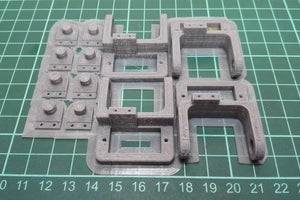

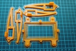
And print them out by your 3D printer.
Please check the configuration of 3D printer before start to print because of it will take a long time about 7~8 hours to print them all. Be patient~~~~
There are my print setting:
- The fill density - 15%
- Nozzle - 0.3mm
- Print speed - 65
you can print these parts separate by color group.
Step 6: Preparing to Assemable
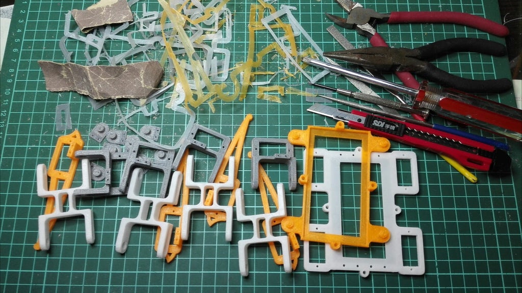
tear down the parts and check the objects printing quality, and using the sandpaper to polish the surface to make it looks good.
Step 7: Assemble the Body


Put the battery between the upper body case and lower body case with 4 screws(M3x25mm)
Step 8: Assemble the Leg
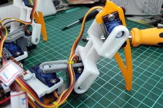
And, install all of servos with legs parts, one leg comes with 3 servos and 4 screws(M1.6x3mm, or glue it anyway)
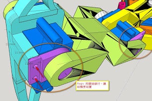
Notes: 1. Connect to all parts with screws and servos, but do not install the servo rocker arm in this step 2. Be sure the leg direction, refer to the picture 1 Re.
Step 9: Integrate 4 Legs to Body
connect all of legs to the body, and check all servos and joints are move smoothly.
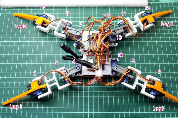
Step 10: Connect Servos to the Main-board
2015-10-04
update the picture1 which is wrong pin assignment.
Place the main-board onto the body-case and use the polymer clay to fix it.
And then, refer to the picture, follow the pin number which mark by pink color to connect all servo wire to the main-board, and green color is present the signal direction of servo wire, yellow connect to "S", red to "+", brown to "-".
Be sure the servo of legs should match the pin number of main-board and leg direction, otherwise, the legs will get crazy...
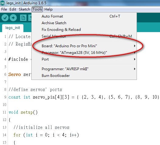
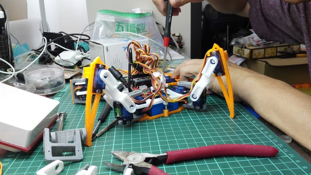
Step 11: Locate the Initial Position for Legs

This is an important procedure, the install procedure:
1. upload the "legs_init" code to Arduino to activate the servos
2. place the legs as the position shows the picture 1, and install the servo rocker arm with screws.
3. tighten all of the screw
legs_init source code:
Attachments
Step 12: Organize the Wires
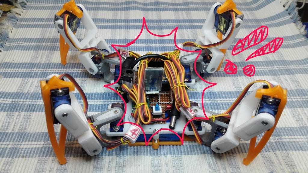
Then, organize the wires of the servos to make it great looking.
Now, all of hardware installation was finished.