BCD Watch (binary coded decimal)

Hi,
How are you? I hope everything is going well.
Check out my youtube for more amazing projects.
There are lots of watches available in the market, like analog, digital, smart watches etc. So I decided to make a BCD watch. You can make this watch or buy it on tindie .
BUY LINK. :- https://www.tindie.com/products/vishalsoniindia/bcd-watch-binary-coded-decimal/
By the way, subscribe to my YouTube channel for more projects like this. I also update my upcoming projects on Instagram.
buy me a coffee! ☕: Donate

What is BCD?
The full form of BCD is binary coded decimal, as its name the binary digits is showing decimal value. It is a very simple representation of decimal numbers in different ways, so you can google BCD or binary coded decimal on google.
Why did I make this?
I want to make a watch which has led, so instead of a simple watch I came with a unique idea. This watch shows time in binary digits. In my engineering I have learned about binary coded decimals, I think some schools also teach this. This unique way of time representation is not easily understood by normal users.
Supplies
- TP4056 Type C module (amazon.com / amazon.in)
- Attiny85 SMD (amazon.com / amazon.in)
- Battery 500mAh (amazon.com / amazon.in)
- MIC5205 (amazon.com / amazon.in)
- Micro SMD Momentary Button (amazon.com / amazon.in)
- RED SMD LED 0603 (amazon.com / amazon.in)
- BLUE SMD LED 0603 (amazon.com / amazon.in)
- 1K Resistor SMD 0603 (amazon.com / amazon.in)
- 1M Resistor SMD 0603 (amazon.com / amazon.in)
- Soldering Iron (amazon.com / amazon.in)
- Soldering Wire (amazon.com / amazon.in)
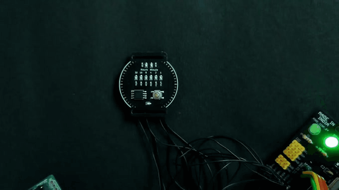
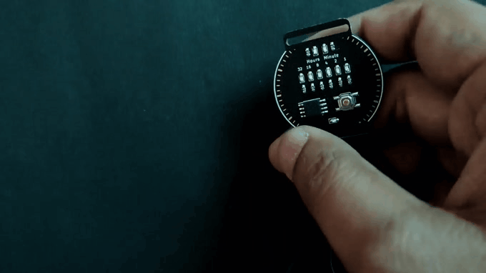
Functionality
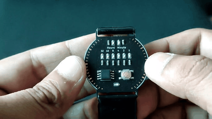
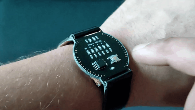
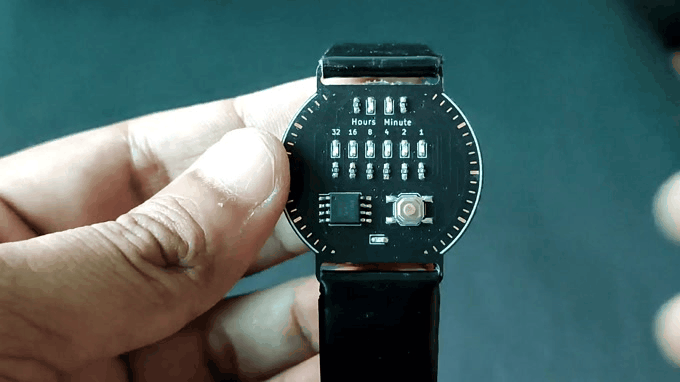
There is a single button in the controller, if you press the button it will show hours and minutes in one second of delay as shown in the image. When it show hours the re led on the top will glow and when it shows minutes the minute led on the top will glow.
When you long press the button it will go in to setting mode,
Firstly the hour led will blink means it is in hour setting mode, the hours can be increased by pressing the button.
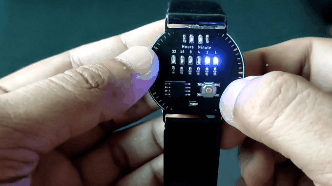
When you long press the button again it will go in minutes setting mode, the minute led will start blinking. The minutes can be increased by pressing the button.
Now to come out from setting mode long press the button again, after long pressing it will show normal hours in minutes with one second of delay as before.
PCB design
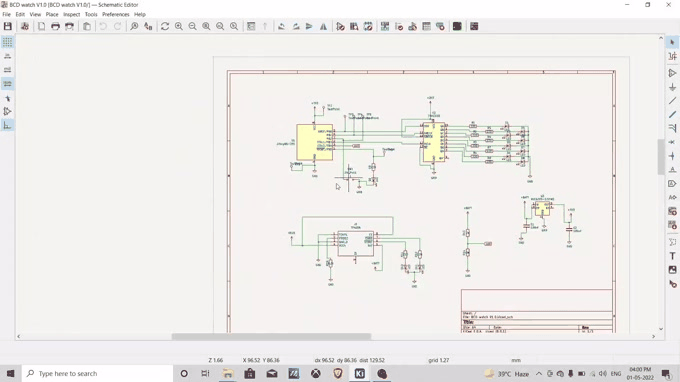
Firstly I have designed the schematic in kicad software, i have used attiny85 as our controller.
There is not much pinout in attiny85 so i have used 74HC595 shift resistor, it increased pinout for leds. I added a button to show time and set the time. For charging I have used a TP4056 circuit which will handle the charging off of the li-po battery.

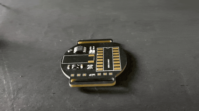
After making the schematic I have routed it on a PCB, as you can see the PCB is round shaped with two slots on it, the slot is to insert the belts for our watch.
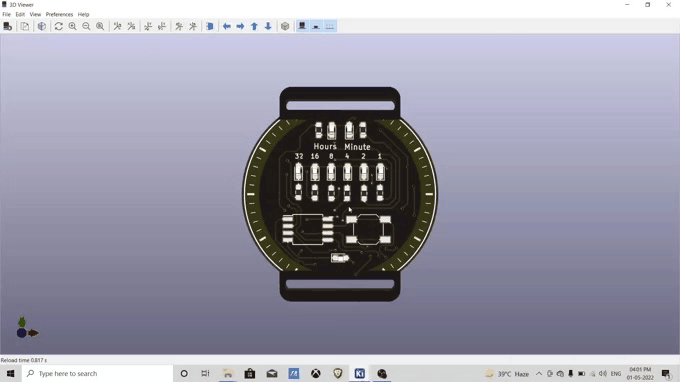
Kicad has a 3d viewer of the PCB, So we can verify what our PCB will look like and all components and vias are placed at the correct place. You can export this stl file to further use in 3D modeling.
All the PCB files are open source and can be downloaded from my github page.
Github link :- https://github.com/vishalsoniindia/BCD-Watch
PCB order

The PCB is sent by PCBWay, the quality of PCB is awesome, they did a very good job to cut the edge of pcb perfectly.
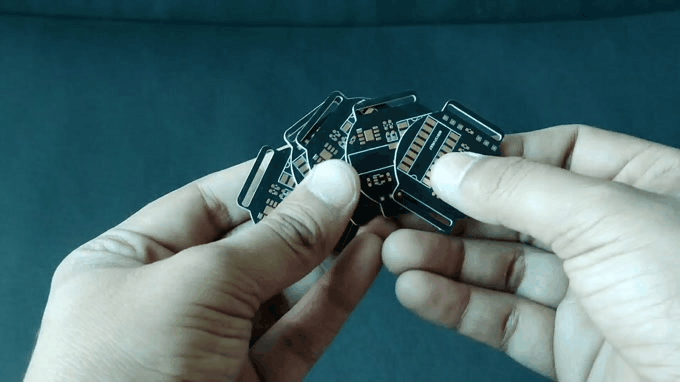
To order PCBs from PCBWay go to the link :- https://www.pcbway.com/
Then upload the gerber file, you can get the gerber file on my github page.
Soldering Front of PCB
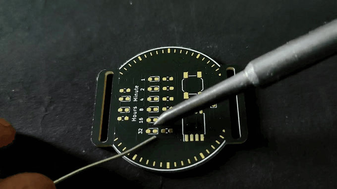
Firstly, I soldered the LEDs and resistors. To solder the LED, solder one leg of led then solder another leg of led, this concept will apply to all SMD components.
After Soldering LED I soldered ATtiny85. First, I soldered one leg of ATtiny85 to fix it in place, then soldered the other 7 legs. Then I soldered the button with the same concept.
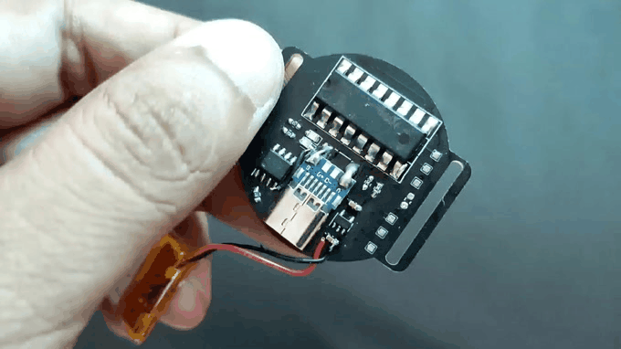
Charging and LDO
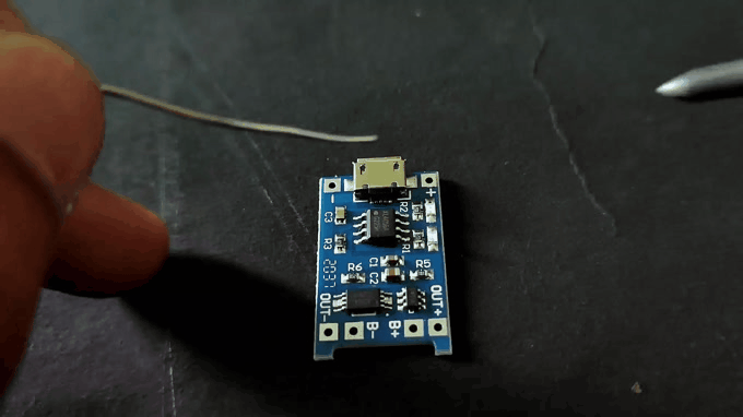
For Charging circuit I have used the TP4056 which is a charging ic, it handles the constant current charging for li-po and li-ion batteries.
Here I did a hack, I have desoldered the TP4056 ic from the module, also extra components like prog resistor and LED. It saved me the cost of buying a new IC.

Then I soldered the TP4056 circuit on the pcb, also here I used a LDO, to regulate the battery voltage to 3.3v, drive the attiny85 and shift resistor.
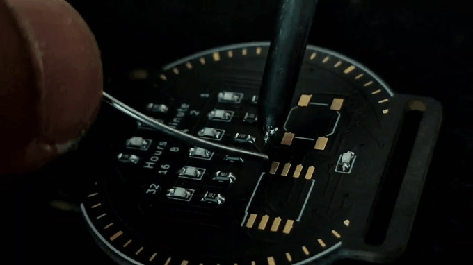
Shift Resistor

Here i did a mistake, i did not checked the pads of IC and used wrong foot print of shift resistor,
I am using a 74HC595 shift resistor.
So I decided to solder the through hole shift resistor by spreading legs. This works for me but I think for the next version I will change it to minimize the size.

Type - C Connector


I have got the type - C female connector already soldered on pcb, it made my wor easy.
I soldered the type-c pcb on the BCD watch with the help of thick wire. I also used super glue to fix the type-c in place, so it will be strong on its place.
Set fuse bits
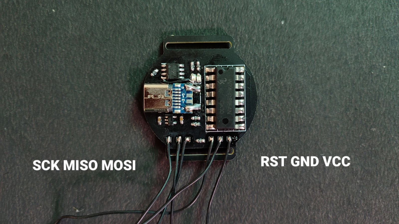
This is the pinout to connect the BCD watch PCB with Arduino as ISP, if you don't know about arduino as ISP, Then checkout this youtube video.
Program any AVR controller :- https://www.youtube.com/watch?v=DxuucFgY1B4&t=303s
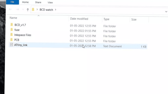
To set fuse bits, first download the folder from my GIthub page.
Github :- https://github.com/vishalsoniindia/BCD-Watch
Open the folder and go to the fuse folder, in the fuse folder click on top bar as shown in image and type CMD to open command terminal.

Open cmd.txt file and copy the first line, paste it in the command terminal. If you see fuse ok means everything is correct.
Copy 2nd line in cmd.txt file and paste it in the command terminal, you will again see fuse ok means your controller is now set on 1Mhz.
Upload the Code
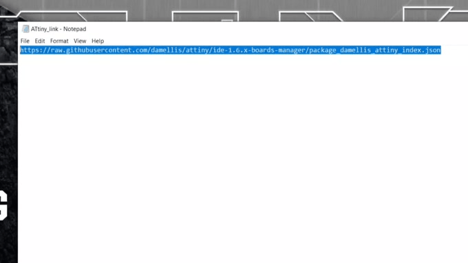
In the same folder you will find the Attiny85_link.txt file, copy the link given in the file or copy it from below.
Open arduino IDE and go to the file then preferences, paste the link in the additional board manager section. Separate other links by comma “,”.

Go to the Tools and boards and then board manager, install attiny85 board.
That it now again goes to the folder which we have downloaded.
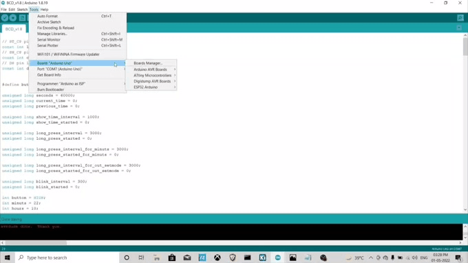
Open the code and go to the Tools, here select board and processor as Attiny85.
Clock should be 1Mhz, the COM port connected to the arduino as ISP. Now go to the sketch and click on upload using the programmer.
AFter uploading the code the watch will show garbage values, so disconnect the ISP and connect it to the external power supply and press the button then everything works fine.
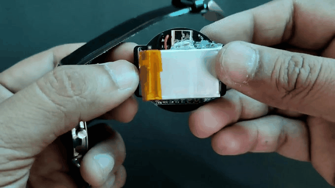
Connect battery
I have connected a 500mAh battery to the Input capacitor of LDO as shown in image,
The connected charger the red LED shows the battery is charging, if you want to know more about LED then check out working of TP4056.
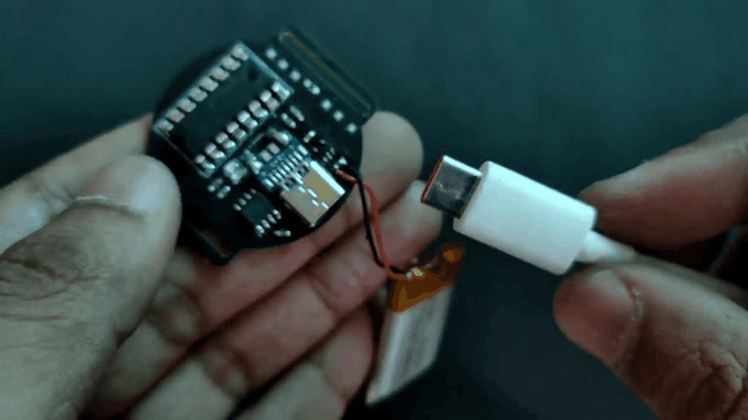
After verifying everything I have out glued the battery to fix it in place, it is not a stable solution but for now it works, later i will use epoxy or zip tie to fix it.
Connecting Belt

I have an old Watch so I decided to remove its belt for our BCD watch. I have removed its glue from the analog watch and re-glued it with the help of super glue. Make sure you don't stitch the belt on the PCB but around the PCB.
And here we go, the thing is done, your watch is ready to rock.
buy me a coffee! ☕: Donate