How We Built TerrainSense
Step 1: Collecting Data
We started by creating our own dataset for pedestrian navigation.
To collect data, we recorded videos using:
- A smartphone camera
- A custom recording device built using a Raspberry Pi Zero 2W and Pi Camera V1
The videos were recorded in different outdoor environments such as roads, footpaths, and pedestrian areas containing various obstacles.
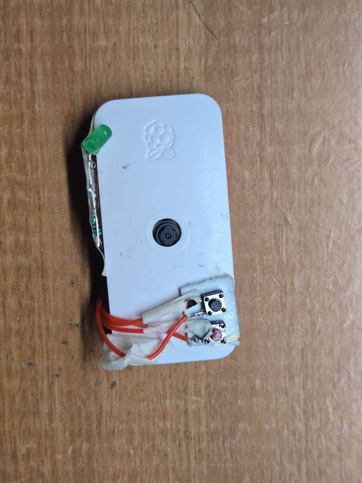
Fig1: Raspberrypi Recording device
Step 2: Creating the Dataset
The recorded videos were converted into image frames.
We then labeled the images with bounding boxes around important obstacles such as:
- Pedestrians
- Vehicles
- Poles
- Road obstacles
- Footpath hazards
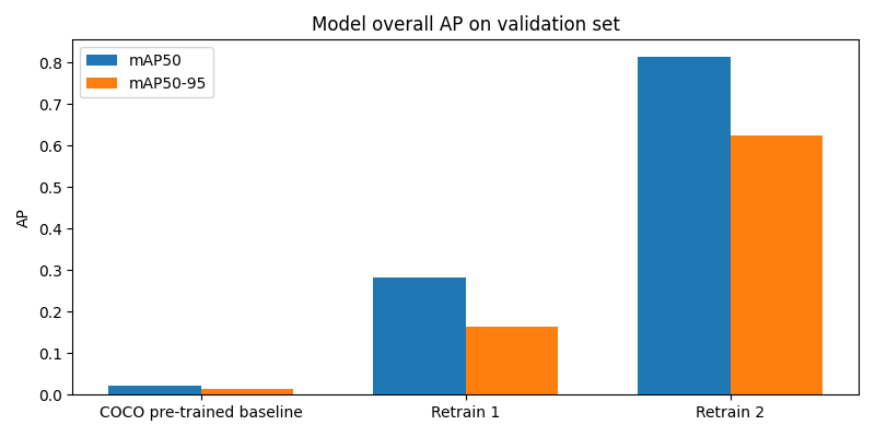
To reduce manual work, we followed an iterative process:
- Manually label a small number of images.
- Train an object detection model.
- Use the trained model to automatically label new images.
- Review and correct the labels.
- Retrain the model with the new data.
- Repeat the process until only a few corrections are needed.
This helped us create a large and accurate dataset more efficiently.
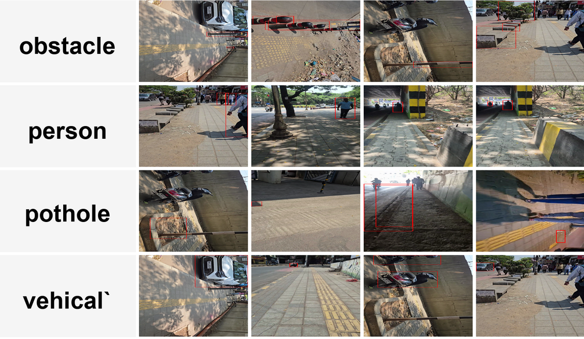
Fig2: annotated Photos
Step 3: Training the Object Detection Model
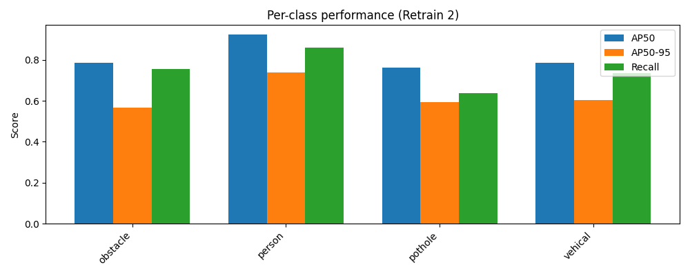
After preparing the dataset, we trained an object detection model to recognize obstacles.
The model learned to identify different objects and their locations in an image.
Once training was completed, the model was optimized so it could run efficiently on a Raspberry Pi.
Step 4: Building the Hardware System
The main system was built using a Raspberry Pi 4 (4GB).
The hardware components include:
- Raspberry Pi 4
- Raspberry Pi Camera Module V1
- VL53L5CX Time-of-Flight (ToF) Sensor
- Earphones for audio feedback
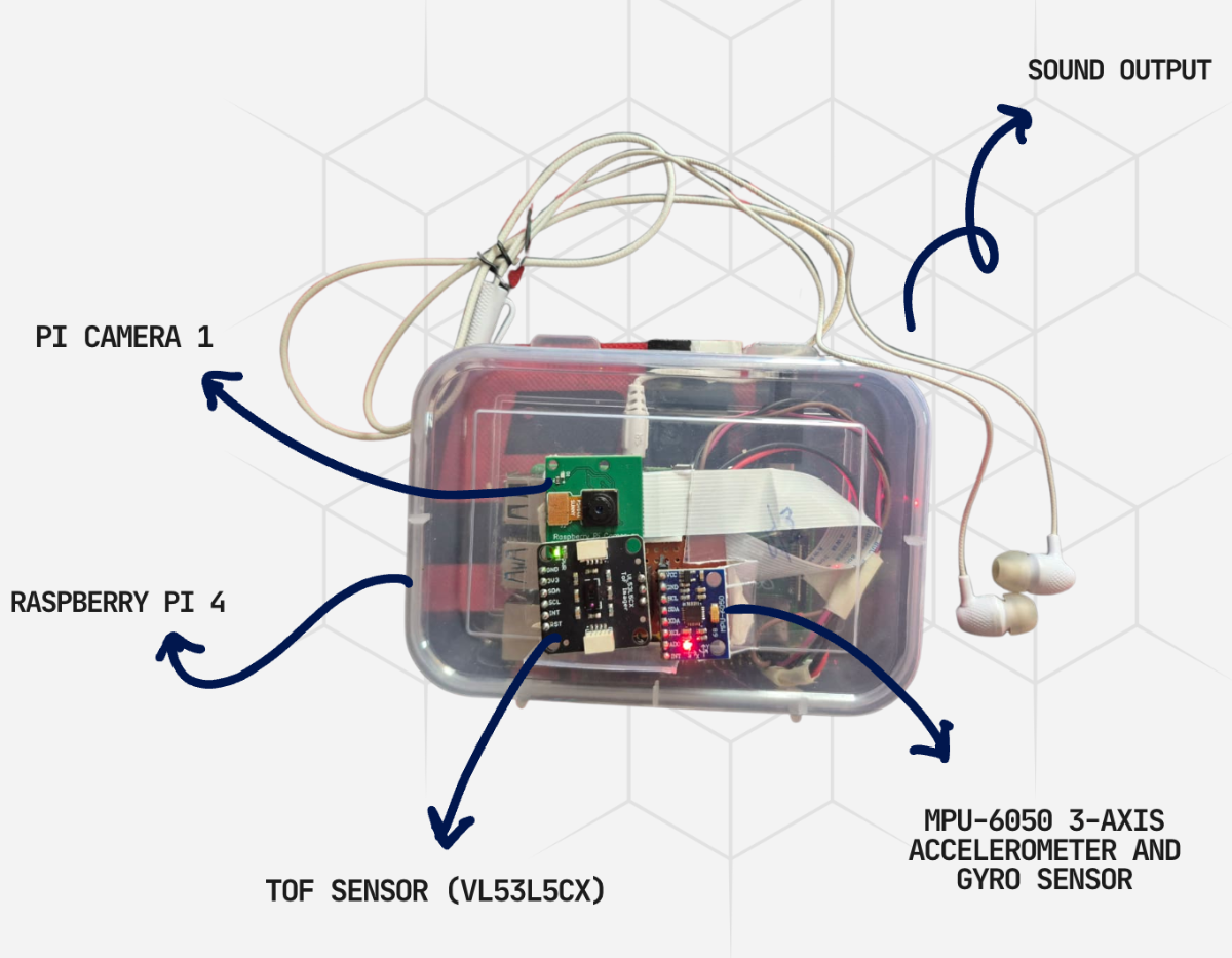
Fig: Whole Module
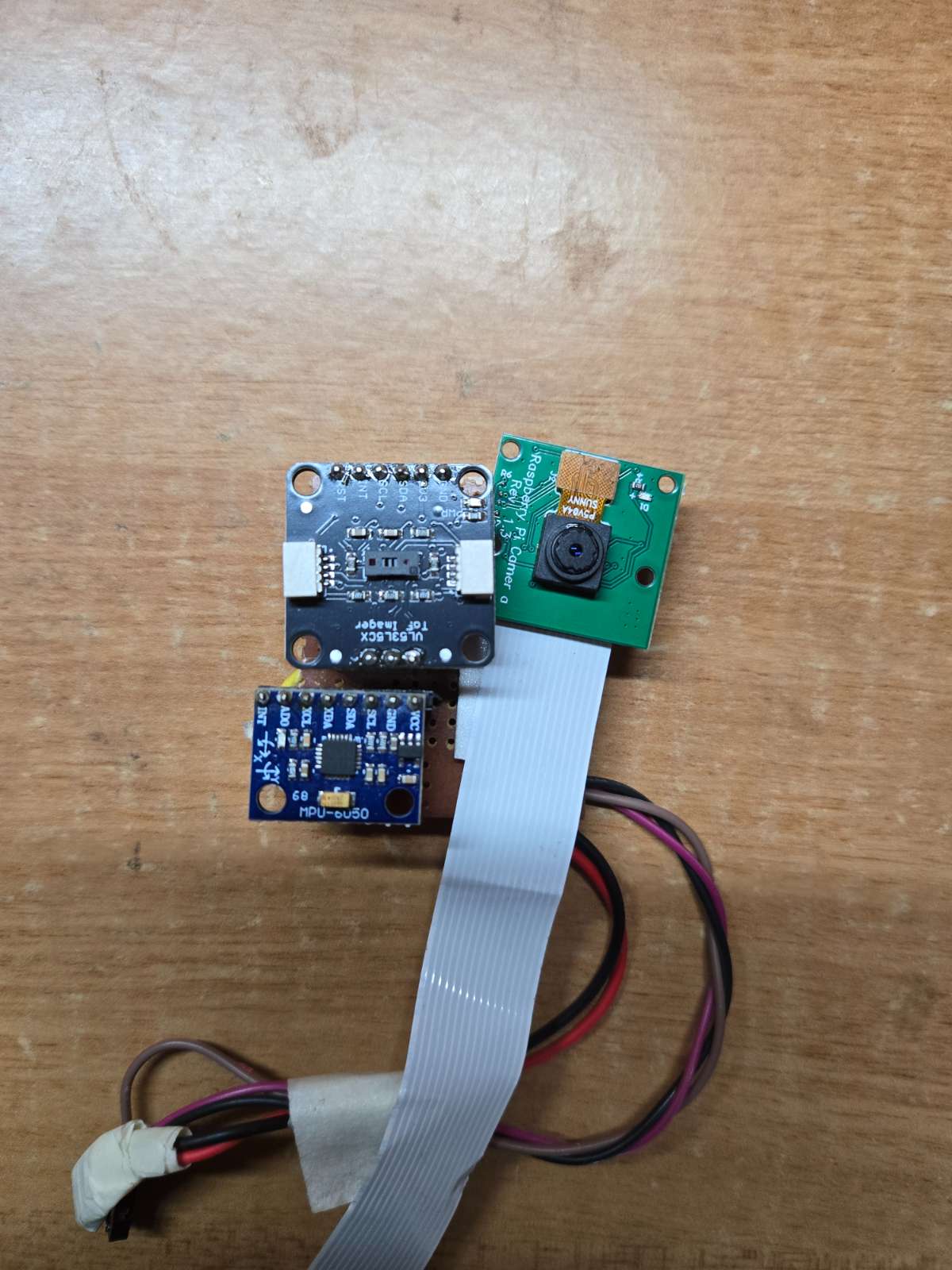
Fig: Sensor Modules close up
The camera captures live video while the Raspberry Pi processes the data in real time.
Step 5: Adding Depth Sensing
To measure the distance of obstacles, we added a VL53L5CX ToF sensor.
The sensor provides an 8×8 grid of distance values, giving 64 depth measurements at the same time.
This allows the system to know how far obstacles are from the user.
.jpg)
Fig: VL53L5CX Time of Flight Sensor
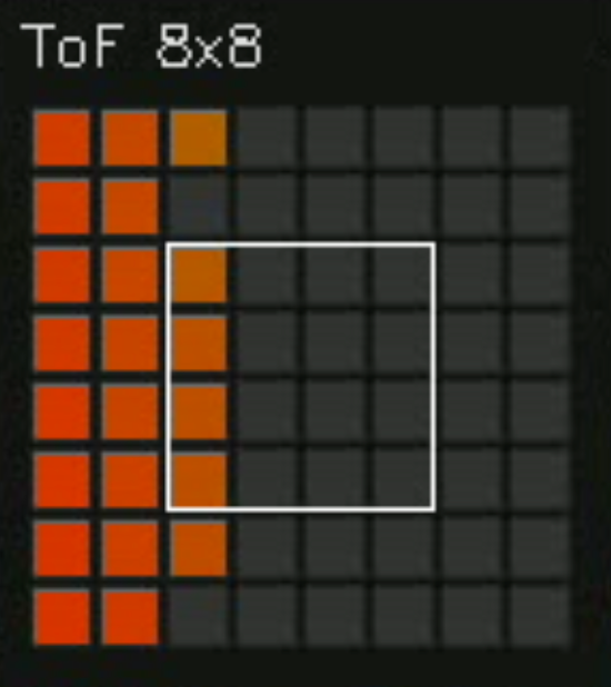
Fig: 8x8 matrix given by the TOF sensor
Step 6: Combining Camera and Sensor Data
We developed a sensor fusion system that combines information from the camera and the ToF sensor.
- The camera identifies what the obstacle is.
- The ToF sensor measures how far away it is.
By combining both sources of information, the system gets a better understanding of the environment.
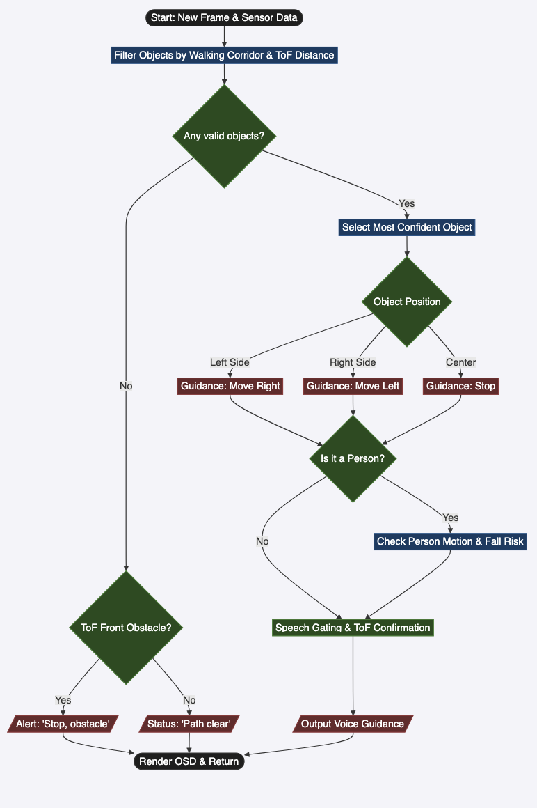
Step 7: Navigation Guidance
Using the combined data, the system decides how the user should move.
Depending on the obstacle position, it generates instructions such as:
- Move Left
- Move Right
- Stop
The instructions are updated continuously as the user moves.
Step 8: Audio Feedback
The navigation instructions are converted into audio mes sages.
These messages are played through earphones so the user can receive guidance without looking at a screen.
This makes the system easy to use while walking.
Insert Image: Audio feedback workflow
Step 9: Fall Detection
We also added a fall detection feature.
The system monitors movement and detects sudden changes in motion that may indicate a fall.
If a fall is detected, the system can trigger safety actions.
Step 10: Live Dashboard
A live monitoring dashboard was developed using Streamlit.
The dashboard displays:
- Live camera feed
- Detected obstacles
- Bounding boxes
- Sensor readings
- ToF heatmap
- Navigation decisions
This helped us test and monitor the system in real time.
Step 11: Testing the System
Finally, we tested TerrainSense in real-world environments with different obstacles and walking conditions.
We evaluated:
- Obstacle detection accuracy
- Distance measurement accuracy
- Navigation guidance
- System response time
- Overall usability
The tests showed that the system can successfully detect obstacles, estimate distances, and provide navigation guidance in real time.