.jpeg)
In this dam project I am using the plc to control the whole setup. Arduino is used to control the water flow sensor and temperature+ moisture sensor. And the final output will come through the Excel sheet.
IMPLEMENTATION OF PROPOSED SYSTEM
In this section the prototype that we have developed to implement the proposed system has been explained. There are various components we used to implement this system. The whole system is divided into various sections and each are explained separately.
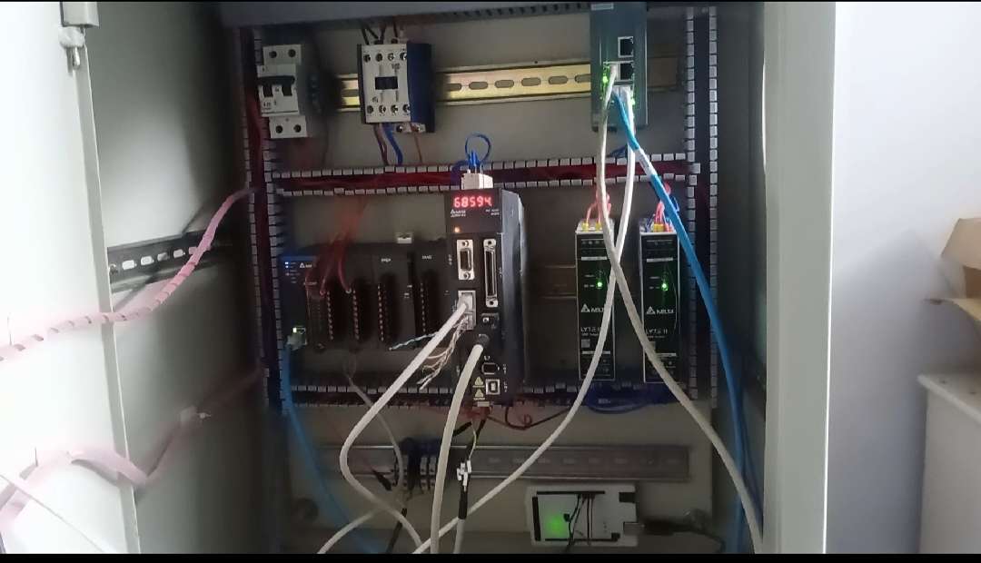
A. Programmable Logic Controller(PLC):
This is heart of our proposed system which controls the entire operation of system. This compact Micrologix 1400 PLC, economical programmable controllers offer several I/O configurations. In this PLC , there are 20 input and 12 output are available .this programmable logic control device of inputs are connected in 5 micro switch and this 5 micro switch are connected toward the SMPS(switch mode power supply ) SMPS is connected in our system because this PLC are required in 24volt dc. The micrologix 1400 PLC of output is connected the DC motor. This motor are connected toward relay driver because motor rotation in two direction.
Here the PLC details:
1. DELTA AS22T.
2. NPN TYPE.
.JPG)
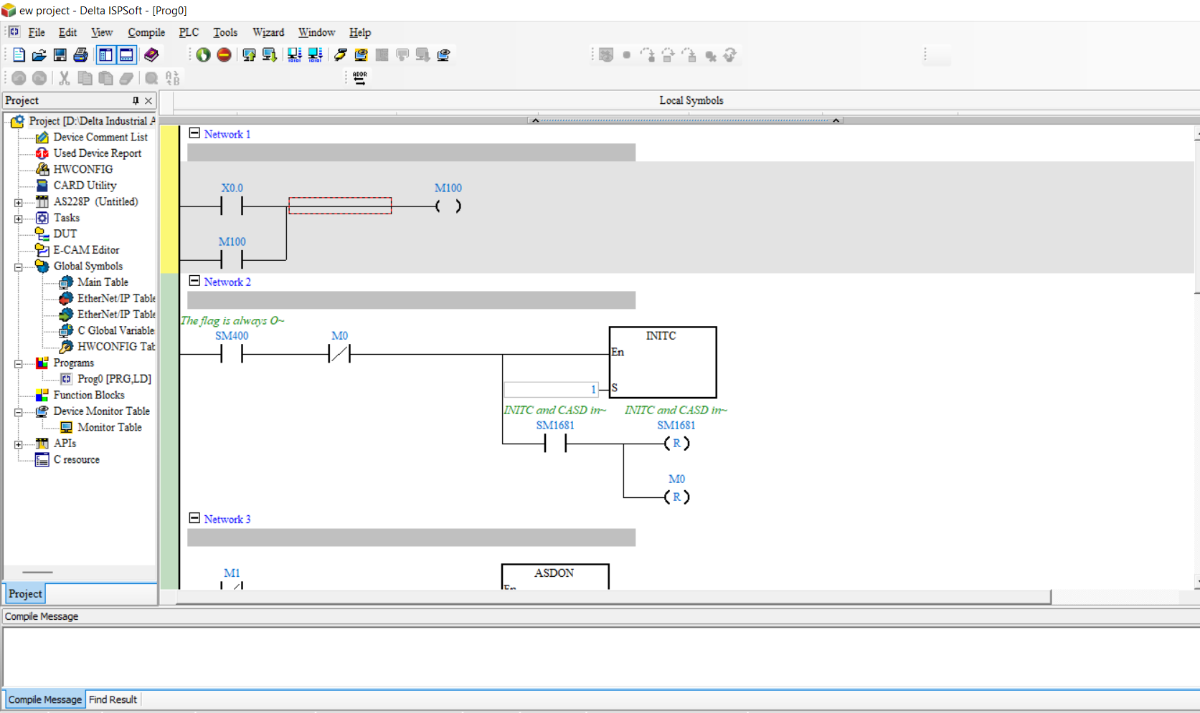
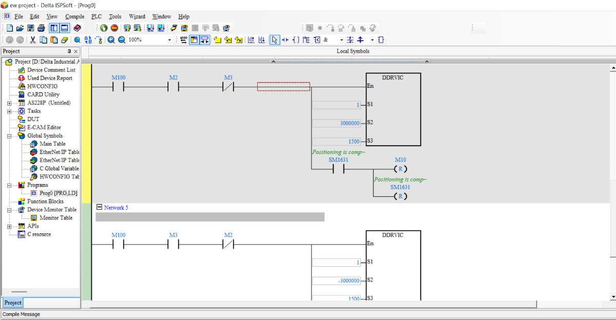
Ladder Diagrams:
Benefits of Barrage/Dam Automation
- Centralized Monitoring &controlling of Barrage/ Dam operations ensures development of Reliable Decision Support System with better response time.
- Improved water management by getting accurate data of Dam/Barrages and its subsidiary canals.
- Accurate and reliable measurement of discharge ensures improved efficiency of Irrigation system.
- Reduction in human intervention minimizes Operational errors.
- Remote monitoring of Barrage/Dam system will ensure the better supervision from management level.
Control Chart:

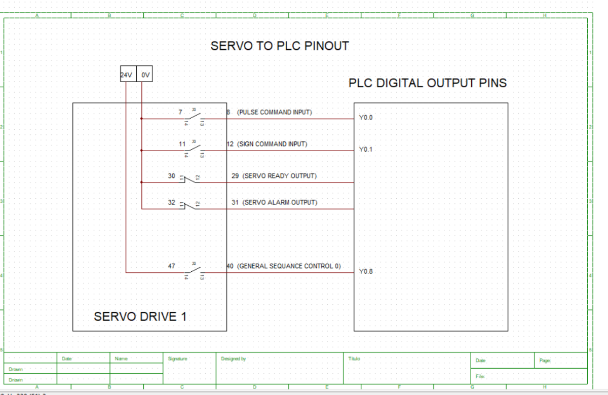
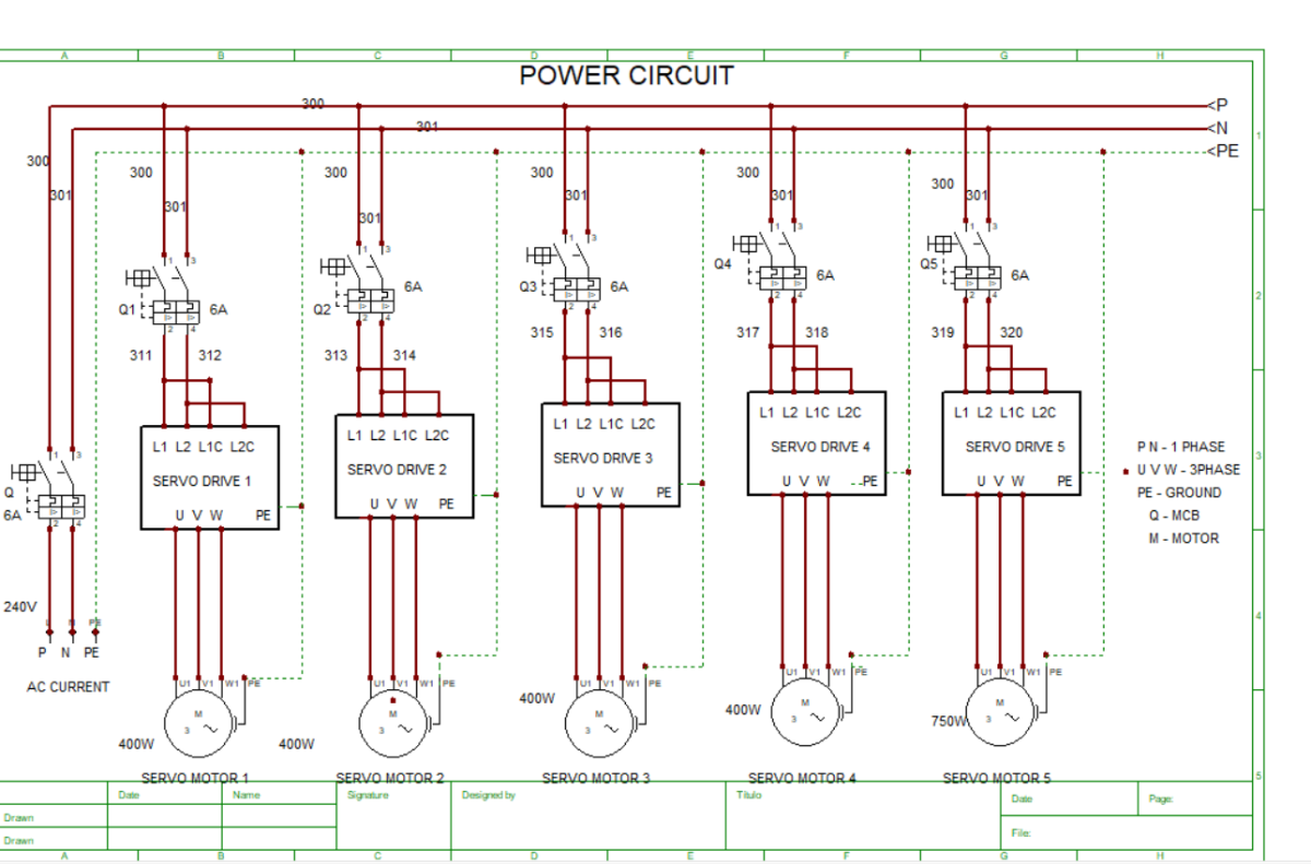
Power Circuit And Control circuit:
B. Sensing element
Sensing element in our proposed system is the hollow ball float which attached to the level switch. Whenever the water level increases the ball will keep floating with above the water level. Whenever the desired level achieved then level switch will trigger the input of PLC which controls the action of gate as opening and closing.
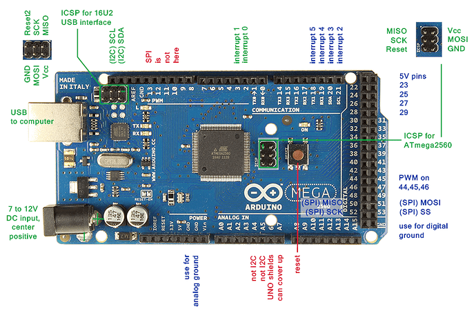
ARDUINO:
1. ARDUINO mega 2560.
2. RTU Modbus communication.
Working video:
C. Gate Control
In gate control assembly there are two doors are used in our proposed system. One gate is used for prior level of water in dam which depends on water level detected by level switch 1. And another gate is used for extreme high level of water in dam which depends on level switch 2. The closing and opening of gate is achieved by the dc motor, the motor shaft is connected with the geared belt which placed on gate assembly. The opening of gate also control by timer with required time application. When the gate is fully opened during this stop action of gate will controlled by limit switch. As gate touches the limit switch the trigger plus is applied to the PLC which stops the motor.
HMI Side:
(0).png)
D. LED and Buzzer
The LED and buzzer are used for alert the people about flood. When the water level increases above the 6 International Journal of Engineering Research in Electronics and Communication Engineering (IJERECE) Vol 2, Issue 3, Mar 2015 extreme high level at the same time buzzing sound will be produced by the buzzer
3.Code for Temperature and water flow sensor:
#include <dht.h>
#define dht_apin A0 // Analog Pin sensor is connected to
dht DHT;
volatile int flow_frequency; // Measures flow sensor pulses
unsigned int l_hour; // Calculated litres/hour
unsigned char flowsensor = 2; // Sensor Input
unsigned long currentTime;
unsigned long cloopTime;
void flow () // Interrupt function
{
   flow_frequency++;
}

void setup(){
  Serial.begin(9600);
  delay(1000);//Delay to let system boot
  Serial.println("DHT11 Humidity & temperature Sensor & flow L per H\n\n");
  delay(1000);//Wait before accessing Sensor
  pinMode(flowsensor, INPUT);
  digitalWrite(flowsensor, HIGH); // Optional Internal Pull-Up
  Serial.begin(9600);
  attachInterrupt(0, flow, RISING); // Setup Interrupt
  sei(); // Enable interrupts
  currentTime = millis();
  cloopTime = currentTime;

}//end "setup()"
void loop(){
  //Start of Program
    DHT.read11(dht_apin);
    Serial.print("Current humidity = ");
    Serial.print(DHT.humidity);
    Serial.print("%");
    Serial.print(",");
    Serial.print("");
    Serial.print("temperature = ");
    Serial.print(DHT.temperature);
    Serial.print("C");
    Serial.print(",");
    Serial.print("");
    delay(2000);//Wait 5 seconds before accessing sensor again.
  //Fastest should be once every two seconds.
  currentTime = millis();
   // Every second, calculate and print litres/hour
   if(currentTime >= (cloopTime + 1000))
   {
      cloopTime = currentTime; // Updates cloopTime
      // Pulse frequency (Hz) = 7.5Q, Q is flow rate in L/min.
      l_hour = (flow_frequency * 60 / 7.5); // (Pulse frequency x 60 min) / 7.5Q = flowrate in L/hour
      flow_frequency = 0; // Reset Counter
      Serial.print(l_hour, DEC); // Print litres/hour
      Serial.println(" L/h");
   }

}// end loop(