
1. Introduction
This project presents an IoT-based Open Canal Water Level Monitoring System that measures water level using a ultrasonic sensor and tracks location using GPS. The collected data is transmitted via GSM to the cloud using Blynk, enabling real-time remote monitoring and alert generation .(Note:I have currently implemented this project on realtime problem in KRS DAM mysuru,Karnataka) .
2. System Overview
The system is built using:
- ESP32 microcontroller (main controller)
- Distance sensor (water level measurement Maxbotics ultra sonic distance sensor)
- GPS module (location tracking)
- TTGO T-Call V1.4 ESP32 SIM800L Wireless Communication Module (main controller) module (data transmission)
- Blynk platform (cloud monitoring)
👉 The system continuously measures water level and sends distance + latitude + longitude to a remote dashboard.
3. Working Principle
A. Water Level Measurement
- The sonar sensor (
SonarEZ0pw) measures distance from sensor to water surface. - Your code calculates:
rawDistance = 739.45 - Sonar.Distance(cm)
👉 This means:
739.45 cm= total canal reference sea level height- Final value = actual water level
✔ Validation:
if (rawDistance > 732.51 && rawDistance < 739.45)
Only valid readings are stored to avoid noise.
B. GPS Location Tracking
Using the TinyGPS++ library:
- GPS data is read via UART (pins 16, 17)
- Latitude & Longitude are extracted:
latitude = gps.location.lat();
longitude = gps.location.lng();
👉 This gives exact canal location.
C. Data Transmission (Serial Communication)
Every 2 seconds, your system sends:
distance,latitude,longitude
Example:
3.33,12.339636,76.607887
D. GSM + Blynk Integration
From your second code :
- Uses SIM800 GSM module
- Connects to internet using:
APN: airtelgprs.com
- Sends data to Blynk:
Blynk.virtualWrite(V0, distanceVal);
Blynk.virtualWrite(V1, longi, lati);
Blynk.virtualWrite(V3, Google Maps link);
👉 This enables:
- Live water level monitoring
- Location tracking on map
E. Alert System (Important Feature)
Your code includes 10 threshold levels:
float thresholds[] = {738.80, 737.50, ..., 736.00};
If water level exceeds threshold:
Blynk.logEvent(events[i]);
👉 This generates:
- Flood warnings
- Critical level alerts
F. Network Reliability System
Your code smartly handles network failure:
- Checks:
- Blynk connection
- GPRS connection
- Network signal
- If failed:
- Reconnects automatically
- Restarts modem
- Power cycles GSM module
👉 This makes system robust and reliable
4. System Flow
- System starts
- Ultrasonic sensor reads water level
- GPS fetches location
- Data sent via Serial
- GSM receives and uploads to Blynk
- Dashboard updates in real-time
- Alerts triggered if threshold crossed
5. Key Features of Your Project
- Real-time water level monitoring
- GPS-based location tracking
- GSM-based remote monitoring
- Cloud dashboard (Blynk)
- Automatic alert system
- Self-recovery network mechanism
6. Advantages
- No manual monitoring required
- Accurate and continuous data
- Works in remote canal areas
- Early flood warning system
- Scalable for multiple canals
7. Conclusion
This project successfully integrates sensor technology, GPS, and IoT communication to create an intelligent canal monitoring system. The use of GSM ensures connectivity even in remote areas, while the alert mechanism enhances safety and water management efficiency.
8. Block Diagram:
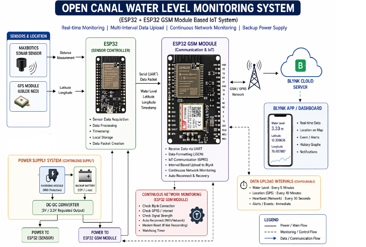
The Open Canal Water Level Monitoring System shown in the block diagram is an IoT-based solution designed to continuously measure and transmit canal water levels along with location data. The system begins with the sensor and location module, where a MaxBotix sonar sensor is used to measure the distance between the sensor and the water surface. This distance is then converted into the actual water level using a predefined reference height. Alongside this, a GPS module (such as NEO-6M) captures the real-time latitude and longitude of the canal, enabling precise location tracking of the monitoring point.
The collected data is processed by the first ESP32 (sensor controller), which acts as the main data acquisition unit. It reads the sonar and GPS inputs, filters invalid readings, and formats the data into a structured form such as “water level, latitude, longitude.” This processed data is then transmitted via UART serial communication to a second controller, ensuring reliable and organized data transfer between system components.
The second unit, an ESP32 GSM module (TTGO T-Call with SIM800), functions as the communication and IoT interface. It receives the data from the sensor ESP32, formats it appropriately, and transmits it to the cloud using GSM/GPRS connectivity. This module connects to the internet using a SIM card and sends the data to the Blynk cloud server, allowing remote monitoring without the need for Wi-Fi infrastructure, which is especially useful in remote canal areas.
On the cloud side, the Blynk platform displays the received data on a mobile application or dashboard. Users can view real-time water levels, GPS location on a map, and historical trends. The system is also capable of generating alerts when the water level crosses predefined thresholds, helping in early flood detection and efficient water management.
A key feature of this system is the multi-interval data upload mechanism, where different types of data are sent at different time intervals. For example, water level data may be transmitted every few minutes, GPS data less frequently, and network heartbeat signals at shorter intervals. This approach optimizes power consumption and reduces unnecessary data usage.
To ensure reliability, the system incorporates continuous network monitoring within the ESP32 GSM module. It regularly checks the status of the GSM network, GPRS connection, and Blynk server connectivity. In case of any failure, the system automatically attempts reconnection, restarts the modem, or performs a power cycle, ensuring uninterrupted operation.
Finally, the entire system is powered by a continuous power supply unit, which may include a solar panel, charging module, backup battery, and DC-DC converter. This setup guarantees 24/7 operation even during power outages, making the system suitable for long-term deployment in remote outdoor environments.
Overall, the block diagram represents a robust and efficient system that integrates sensing, processing, communication, and cloud monitoring to provide a reliable solution for real-time canal water level monitoring.
Fabrication
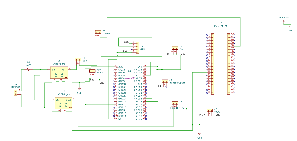
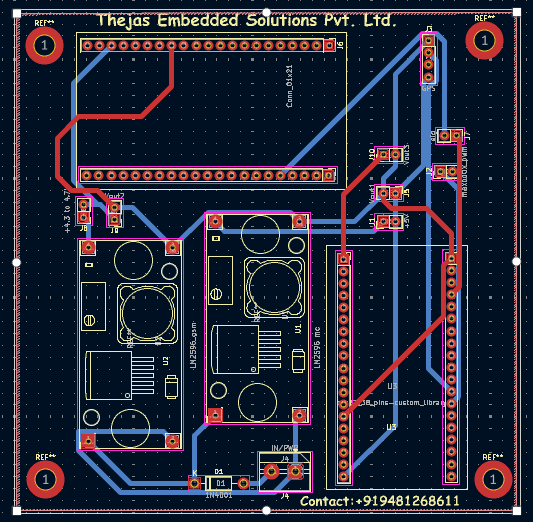
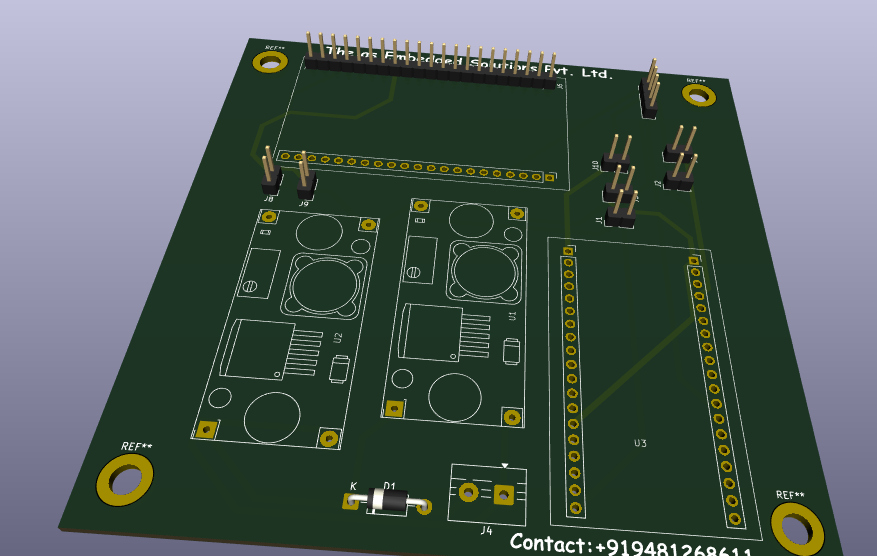
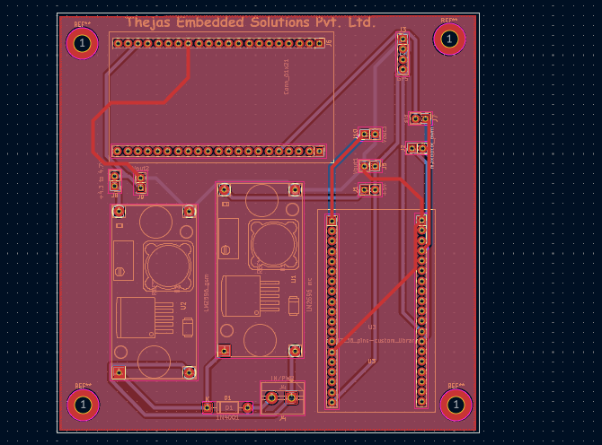
After analyzing the circuit and developing the prototype, I finalized the schematic design uisng KICAD PCB EDA refer the below image also you can check end of the publication attachments.Since the ESP32 GSM PCB schematic symbols, and footprint libraries were not readily available, a custom schematic and PCB layout were designed and developed using KiCad. For final layout of design my Product board u can refer my GitHub link https://github.com/thejastj/open-canal-schematic-.git)
Steps Involved Building project
Steps 1:Components Required for Building an IoT-Based Open Canal Water Level Monitoring System
.jpeg)
The proposed system is designed using two dedicated controllers, namely the ESP32 and the ESP32 GSM integrated with the SIM800L module, to enhance system reliability, fault identification, and future scalability. The utilization of separate controllers enables efficient isolation of hardware and communication-related issues, thereby simplifying the process of identifying whether a malfunction originates from the sensing unit or the network communication module. This architecture also provides flexibility for incorporating additional advanced features and functionalities in future developments of the project.
For liquid level monitoring, the system employs the MaxBotix MB1240 Ultrasonic Sensor ultrasonic sensor, which offers a high narrow-beam output with long-range sensing capability, ensuring accurate and stable level measurement. Power regulation within the system is achieved using two LM2596 Voltage Regulator Module voltage regulator modules. One regulator is configured to provide a stable 5V supply for the sensors and the ESP32 controller, while the second regulator is adjusted to approximately 4.7V to ensure reliable and efficient operation of the ESP32 GSM module and the SIM800L communication unit.
Furthermore, a GPS module is integrated into the system to determine the real-time geographical location of the device. This feature not only supports location-based monitoring but also assists in tracking the device in case of theft or unauthorized movement. A protection diode is incorporated into the circuit design to safeguard the hardware components against reverse polarity connections, thereby enhancing the safety, reliability, and durability of the overall system.
The hardware implementation and physical arrangement of all the required components are illustrated in the above image, and the corresponding components have been previously detailed in the prerequisites section.
Step2 :The assembly and soldering of components on the PCB is carried out by referring to the schematic diagram and PCB layout designed using KICAD, which can be found in the PDF attached at the end of the project document.
.png)
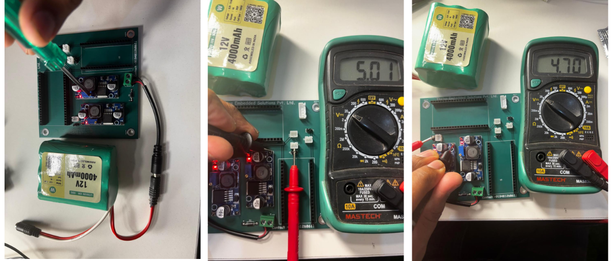
Step3:Before other components connecting its very important to set voltage of two dc to dc converter LM2596 with input battery voltage 12V 4Ah battery for 4.7V and 5V as discussed in step1.
Step3:It is time to connect the supply jumpers that were removed before voltage setting, along with the ESP32, ESP32 GSM module, sensor, and GPS module all using JST cables .Addition a fuse can be add at the input before the battery connection for the protection of circuit.
.png)
Step4:Finally, the circuit is powered by a battery, and the working condition is checked before programming. Please power the circuit only after completing the circuit analysis and verifying all connections. At the initial power supply input, a diode is used to protect the board from reverse polarity connections. Final board condition after power supply verification.
.png)
Step5: The circuit is now ready for programming using the Arduino IDE. Before uploading the code, create an account in Blynk IoT and configure the required template for the project. After creating the template, copy the Template ID, Device Name, and Authentication Token, and update them in the Arduino code for proper cloud communication and monitoring.
The sensor should also be calibrated according to the required depth measurements and calculations with reference to sea level conditions to ensure accurate readings and reliable monitoring performance. Refer to the below screenshots and steps for programming and calibrating the device.
Step 5.1:Create a Blynk account
.png)
Step 5.2:Create a project templete name in my templete select controller and meythod of communication device i my case its GSM
.png)
Step 5.3: Click on created template to create datastream points
.png)
Step 5.4:Select the data streams and create virtual pins in Blynk IoT .The values should be declared by referring to the Arduino code, where each sensor and output device is assigned to a specific virtual pin for monitoring and control.
.png)
.png)
Step 5.5:Add widgets and assign the corresponding virtual pins.
.png)
Step 5.6:Add the created template to the live project by clicking on “Devices” and selecting “Add New Device.”
.png)
Step 5.7:Copy the Firmware confirmations
.png)
Step 5.8:Paste the credentials into the ESP32 GSM code Using Arduino IDE.
.png)
Step 5.9:Upload the sensor and GPS code to the ESP32, and slightly calibrate the sensor values according to the project requirements. In this case, the calibration is performed considering sea level conditions using the Arduino IDE.Final after upload we can observe the data at serial with Level and coordinate values.
.png)
Step 5.10: Insert any 2G-based SIM card; Airtel worked perfectly in this setup.
.png)
Step 5.11: Connect back ESP32 GSM ,Final Outcome of Project With Help of BlynkIoT is Illustrated below with images
.png)
.png)
9. Implementation on Real World problem:
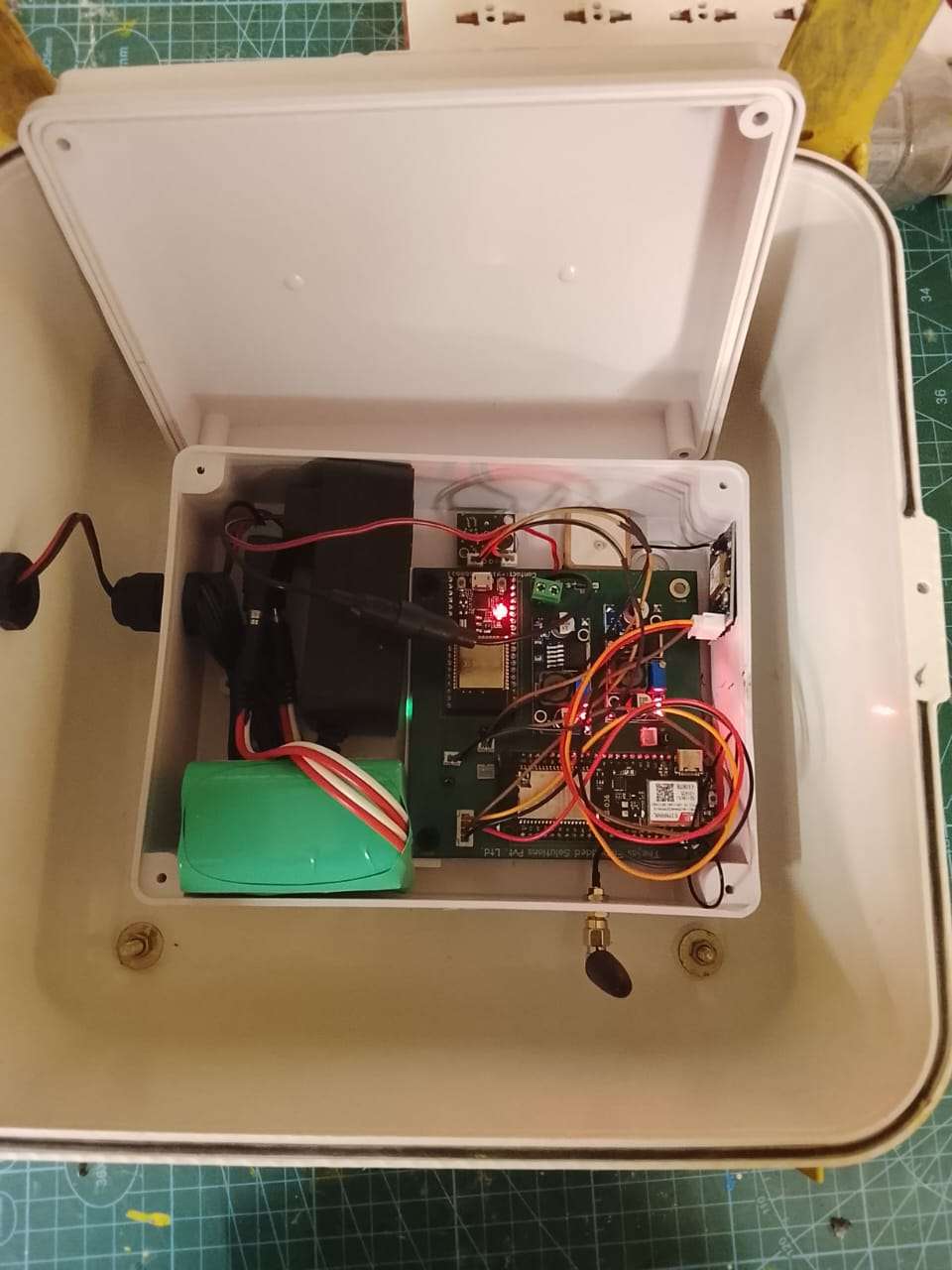
Fig 1,shows the device setup with internal battery pack for power backup with ip casing box
The final device is enclosed inside a weatherproof IP-rated casing and is further protected using an external IP protection box to ensure reliable operation under harsh environmental conditions such as sunlight, rain, dust, and moisture. A cable junction box is provided for safe and organized cable management, preventing damage to wiring connections and improving maintenance safety. The system is powered through a 230V AC supply connected to a battery charging unit, which continuously charges the backup battery and ensures uninterrupted operation during power failures. This dual-layer protection and power management setup enhances the durability, safety, and long-term reliability of the overall monitoring system.
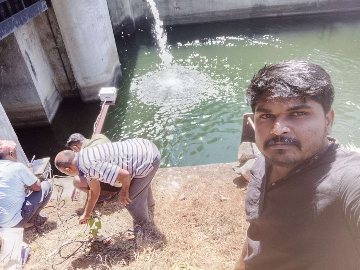
Fig 2 installation of device at near by power station open canal discharge from KRS DAM
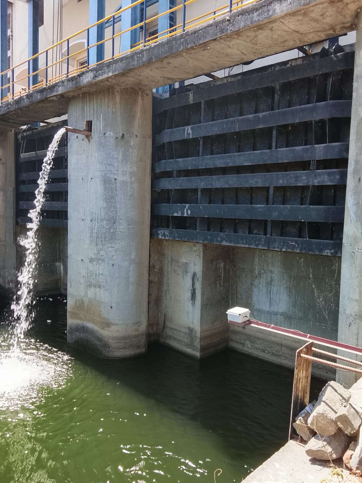
Fig3 After final installation
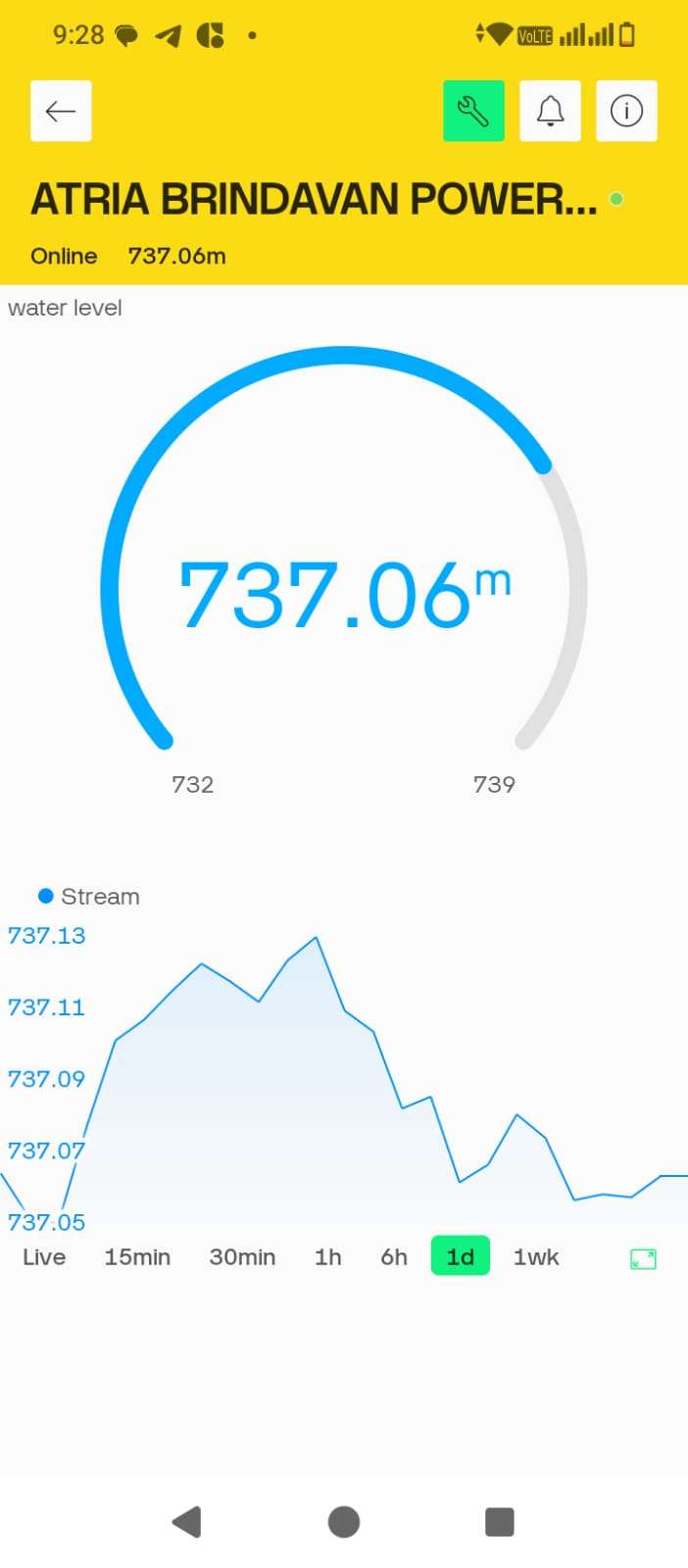
Fig 4 Andriod application for monitring water level with avg graph represenation with real time data
.png)
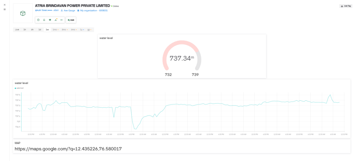
Fig5: Web application more detailed sensor output with device location.
My Story Behind Bulding IoT open canal water level monitoring project
Introduction To Hardware and detailed expliantion of circuit
Actual working demo observed alongside the product.
Real World Implementation for Open canal water level monitoring.