
Problem Statement 1:
Nurses in hospitals frequently perform exhausting and repetitive tasks such as collecting medicines from the pharmacy and delivering them to patient rooms. This constant movement leads to fatigue, reduced efficiency, and increases the likelihood of human errors, which can compromise patient safety. Moreover, frequent direct contact between nurses/doctors and patients increases the chance of transmitting new germs—both from staff to patients and from patients to staff—especially in contagious environments.


Problem Statement 2:
Hospitals are environments where infectious pathogens can remain active for long periods, posing serious health risks to both patients and medical staff. Manual cleaning and disinfection methods are often inconsistent, time-consuming, and expose cleaning personnel to harmful microorganisms. Due to the continuous movement of patients, doctors, and nurses, maintaining a consistently sterile environment becomes difficult.


Proposed Solution:
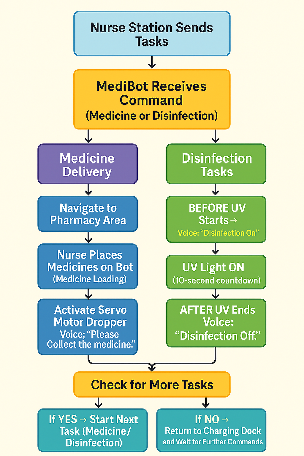
To address both challenges—nurse fatigue caused by repetitive medicine delivery tasks and inconsistent room disinfection—MediBot provides a fully autonomous, safe, and reliable robotic solution designed specifically for hospital environments.
MediBot combines computer vision, autonomous navigation, microcontroller-based actuation, and UV-C disinfection technology to perform two critical healthcare operations without requiring human intervention:
1. Autonomous Medicine Delivery
MediBot independently travels from the pharmacy to assigned patient rooms using ArUco-based vision navigation.
Once it reaches the designated room, a servo-powered dispensing mechanism automatically drops the medication, ensuring accurate and contact-free delivery.
This reduces nurse workload, prevents fatigue, and minimizes direct human–patient contact, thereby lowering cross-infection risks.
2. Automated UV Disinfection
MediBot autonomously navigates to rooms requiring sanitization.
Using a WiFi-connected micro-ROS control system, the robot activates a UV-C disinfectant LED mounted on a ESP32-C6 microcontroller.
The robot waits inside the room for a fixed UV exposure time (e.g., 10 seconds), ensuring effective pathogen inactivation.
This ensures consistent, timed, and safe disinfection of rooms, reducing infection spread and protecting both medical staff and patients.
Key Features:
- Hands-free operation: Fully automated from start to finish.
- Real-time status feedback: ROS2 topics report delivery, dispensing, and disinfection states.
- Vision-guided precision: ArUco markers ensure centimetre-level accuracy in navigation.
- Safe & non-invasive: Avoids unnecessary human exposure to UV-C radiation and infectious surfaces.
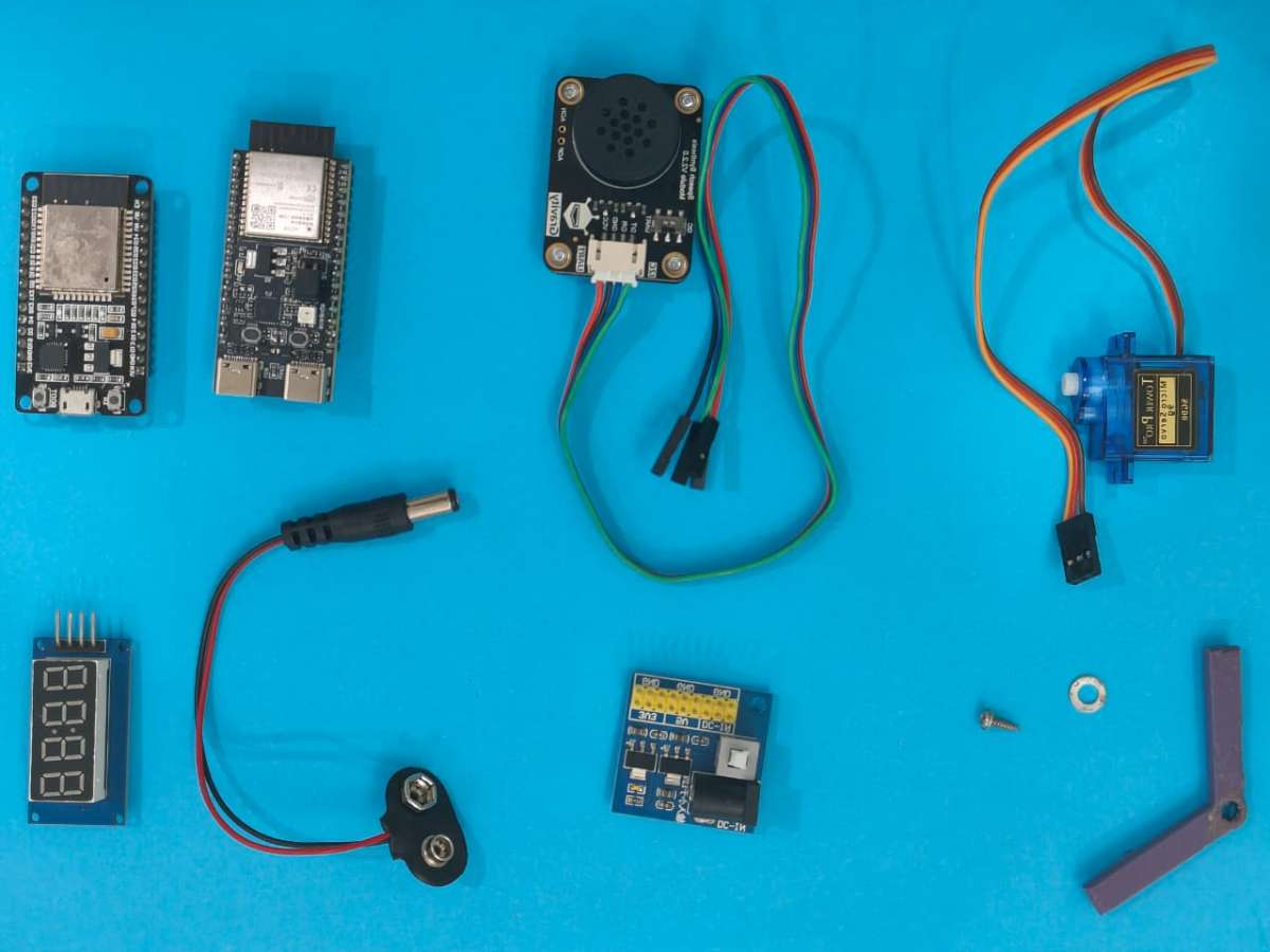
DigiKey My-list
Here are the components I have used for this MediBot. I’ve created a custom DigiKey My-List that includes the manufacturer part numbers for each item. You can view the complete list using the link below.
Link: https://www.digikey.in/en/mylists/list/USJJ9KHIO1
3D printed:
Building MediBot:
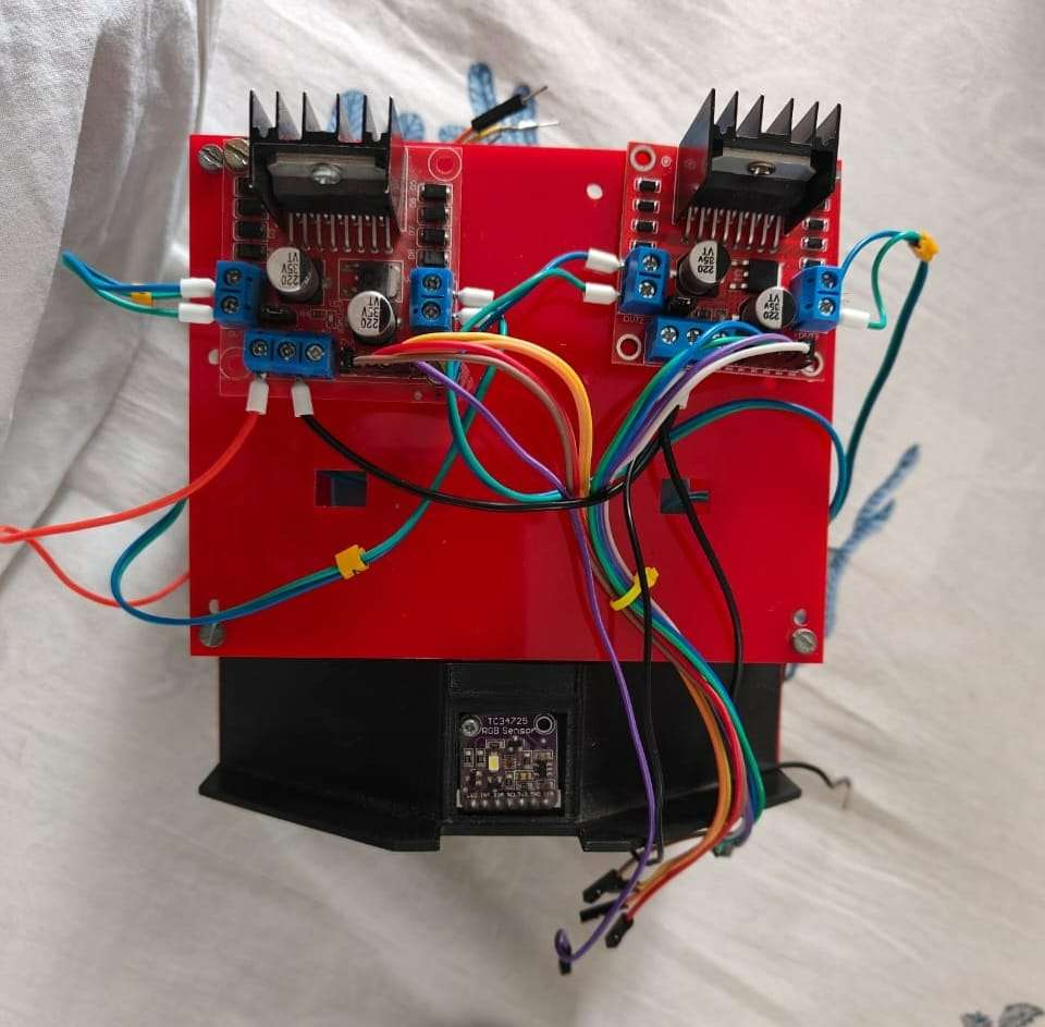
Step 1 — Assemble the Robot Chassis
1.1 Components Required
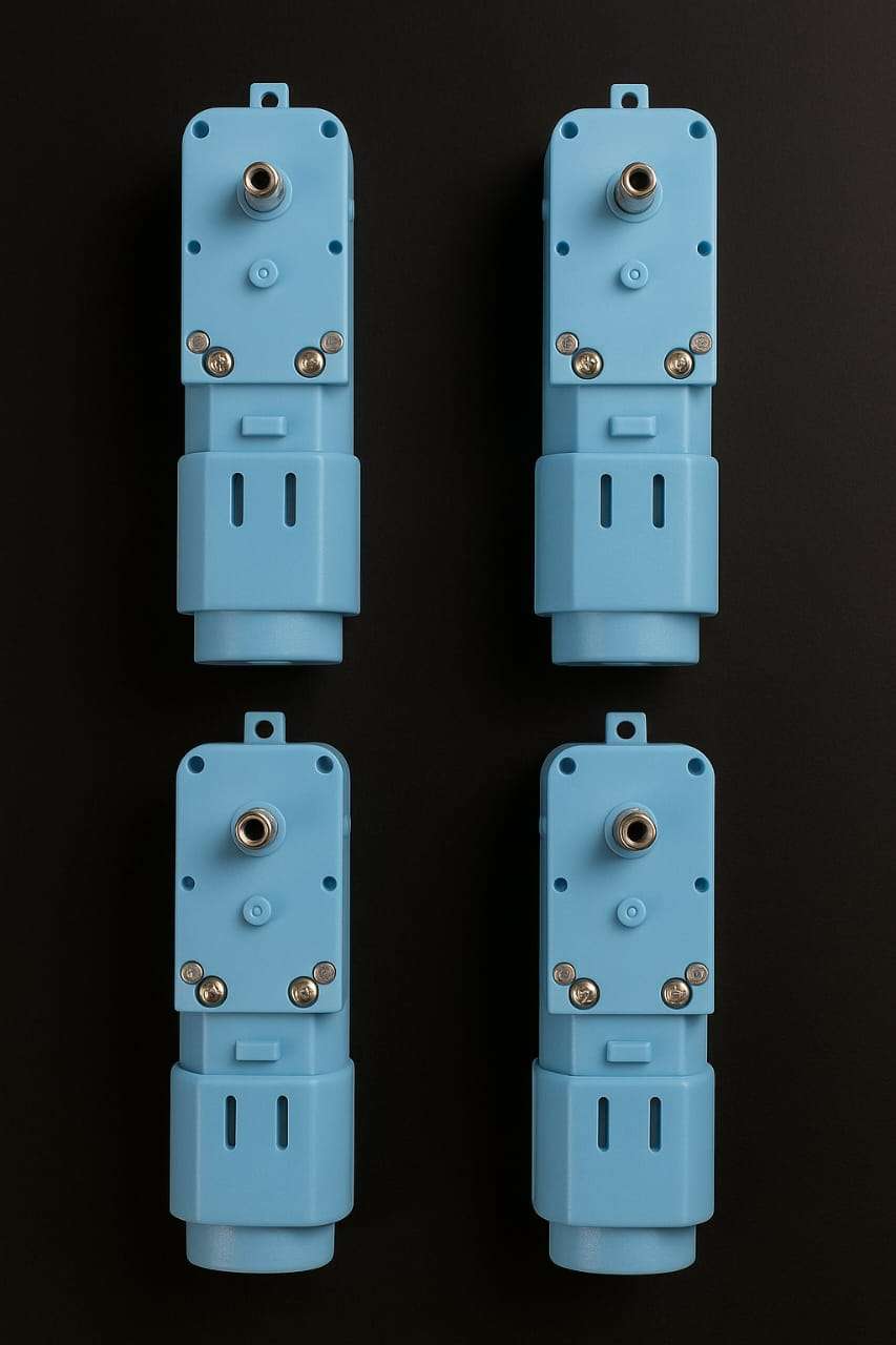
- 4 × DG01D geared motors
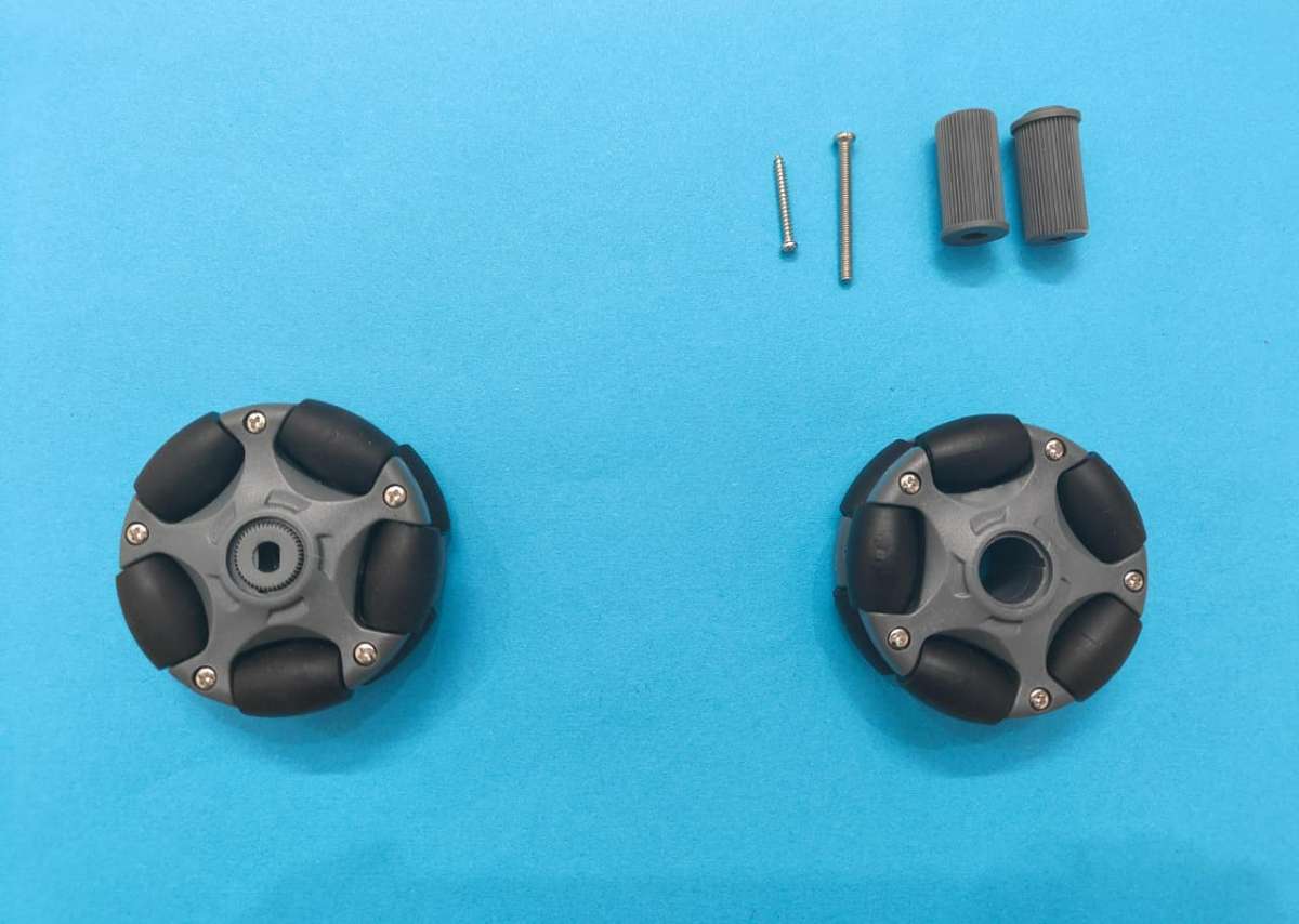
- 4 × Omni-wheels / Mecanum wheels
- Acrylic base plate (your 3mm–5mm sheet)
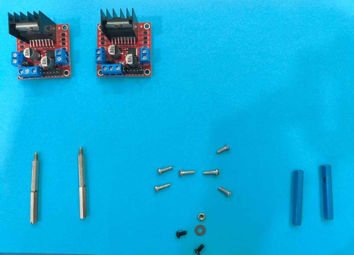
- Screws, nuts, standoffs
- 3D-printed motor mounts (your custom piece)
- Battery pack
1.2 Mount the Motors
- Align the DG01D motors with the 3D-printed holders.
- Place holders at each corner of the acrylic base.
- Screw the holders firmly using M3 screws.
- Attach the Omni wheels to each DG01D motor shaft.
.jpg)
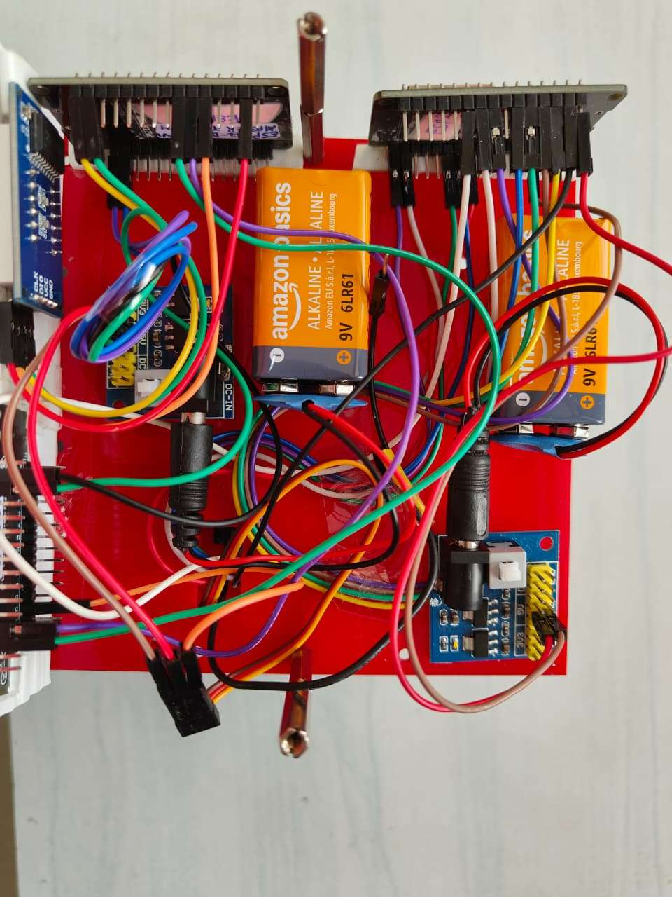
1.3 Fix the Top Plate
- Use 25mm standoffs to mount a second acrylic sheet above the motors.
- This plate will hold your ESP32 boards, power distribution, and wiring.
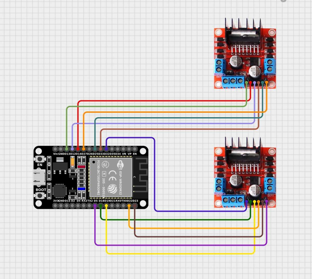
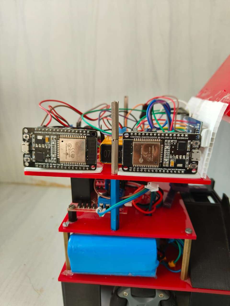
Step 2 — Install Motor Driver & Drive ESP32 DEVKITV1 (Board A)
2.1 Components
- ESP32 DEVKIT V1 – Board A
- L298N or L9110S motor drivers (depending on your build)
- Jumper wires
- Common Ground
2.2 Wiring Motor Drivers to ESP32 (Board A)
| ESP32 Pin | Motor Driver | Description |
|---|---|---|
| GPIO 33 | IN1 | Motor A |
| GPIO 25 | IN2 | Motor A |
| GPIO 14 | IN3 | Motor B |
| GPIO 12 | IN4 | Motor B |
| GPIO 22 | IN5 | Motor C |
| GPIO 23 | IN6 | Motor C |
| GPIO 18 | IN7 | Motor D |
| GPIO 19 | IN8 | Motor D |
| 5V | Vcc | Power |
| GND | GND | Common ground |

2.3 Flash Drive Code (micro-ROS subscriber)
#include <Arduino.h>
#include <WiFi.h>
#include <micro_ros_arduino.h>

#include <rcl/rcl.h>
#include <rclc/rclc.h>
#include <rclc/executor.h>
#include <geometry_msgs/msg/twist.h>

// ---------------- Wi-Fi + micro-ROS Agent ----------------
const char* WIFI_SSID = "11R5G";
const char* WIFI_PASS = "12312312";
const char* AGENT_IP  = "172.29.29.3";
const uint16_t AGENT_PORT = 8888;

// ---------------- Motor Pins -----------------------------
const int IN1 = 33;  // Wheel 1 - Top
const int IN2 = 25;
const int ENA = 27;

const int IN3 = 14;  // Wheel 2 - Right
const int IN4 = 12;
const int ENB = 13;

const int IN5 = 22;  // Wheel 3 - Bottom
const int IN6 = 23;
const int ENC = 5;

const int IN7 = 18;  // Wheel 4 - Left
const int IN8 = 19;
const int END = 32;

// ---------------- micro-ROS objects -----------------------
rcl_subscription_t twist_sub;
rcl_node_t node;
rclc_support_t support;
rcl_allocator_t allocator;
rclc_executor_t executor;
geometry_msgs_msg_Twist twist_msg;

// ---------------- Motor Setup ----------------------------
void setupMotorPins() {
  pinMode(IN1, OUTPUT); pinMode(IN2, OUTPUT); pinMode(ENA, OUTPUT);
  pinMode(IN3, OUTPUT); pinMode(IN4, OUTPUT); pinMode(ENB, OUTPUT);
  pinMode(IN5, OUTPUT); pinMode(IN6, OUTPUT); pinMode(ENC, OUTPUT);
  pinMode(IN7, OUTPUT); pinMode(IN8, OUTPUT); pinMode(END, OUTPUT);

  digitalWrite(ENA, HIGH);
  digitalWrite(ENB, HIGH);
  digitalWrite(ENC, HIGH);
  digitalWrite(END, HIGH);

  Serial.println("[SETUP] Motor pins configured, EN pins HIGH");
}

// ---------------- Motor Direction Function ----------------------------
void setMotor(int in1, int in2, int dir, const char* name) {
  // Special fix: Reverse logic for Bottom Wheel (W3)
  if (strcmp(name, "Wheel 3 - Bottom") == 0) {
    if (dir > 0) {
      digitalWrite(in1, LOW);
      digitalWrite(in2, HIGH);
    } else if (dir < 0) {
      digitalWrite(in1, HIGH);
      digitalWrite(in2, LOW);
    } else {
      digitalWrite(in1, LOW);
      digitalWrite(in2, LOW);
    }
  }
  else {
    // Normal logic for all other wheels
    if (dir > 0) {
      digitalWrite(in1, HIGH);
      digitalWrite(in2, LOW);
    } else if (dir < 0) {
      digitalWrite(in1, LOW);
      digitalWrite(in2, HIGH);
    } else {
      digitalWrite(in1, LOW);
      digitalWrite(in2, LOW);
    }
  }

  Serial.print("[MOTOR] "); Serial.print(name);
  Serial.print(" → "); Serial.println((dir > 0) ? "FORWARD" : (dir < 0) ? "BACKWARD" : "STOP");
}

// ---------------- Movement Logic -------------------------
// ---------------- Movement Logic (updated thresholds) -------------------------
void moveRobot(float linear_x, float linear_y) {
  int w1 = 0, w2 = 0, w3 = 0, w4 = 0;
  const float ACTIVATE_THRESHOLD = 0.02; // lowered from 0.1

  // Forward/Backward → Diagonal pair: W1 (Top) + W3 (Bottom)
  if (fabs(linear_x) > ACTIVATE_THRESHOLD && fabs(linear_y) <= ACTIVATE_THRESHOLD) {
    if (linear_x > 0.0) {
      w1 = 1; w3 = 1;
      Serial.println("[MOVE] FORWARD (Diagonal W1 + W3)");
    } else {
      w1 = -1; w3 = -1;
      Serial.println("[MOVE] BACKWARD (Diagonal W1 + W3)");
    }
  }

  // Left/Right → Other diagonal pair: W2 (Right) + W4 (Left)
  else if (fabs(linear_y) > ACTIVATE_THRESHOLD && fabs(linear_x) <= ACTIVATE_THRESHOLD) {
    if (linear_y > 0.0) {
      w2 = 1; w4 = 1;
      Serial.println("[MOVE] RIGHT (Diagonal W2 + W4)");
    } else {
      w2 = -1; w4 = -1;
      Serial.println("[MOVE] LEFT (Diagonal W2 + W4)");
    }
  }

  // If both axes exceed threshold, choose the dominant axis (prevents conflicting commands)
  else if (fabs(linear_x) > ACTIVATE_THRESHOLD && fabs(linear_y) > ACTIVATE_THRESHOLD) {
    if (fabs(linear_x) >= fabs(linear_y)) {
      if (linear_x > 0.0) { w1 = 1; w3 = 1; Serial.println("[MOVE] FORWARD (dominant X)"); }
      else { w1 = -1; w3 = -1; Serial.println("[MOVE] BACKWARD (dominant X)"); }
    } else {
      if (linear_y > 0.0) { w2 = 1; w4 = 1; Serial.println("[MOVE] RIGHT (dominant Y)"); }
      else { w2 = -1; w4 = -1; Serial.println("[MOVE] LEFT (dominant Y)"); }
    }
  }

  else {
    Serial.println("[MOVE] STOP (All Motors)");
  }

  // Apply motor directions
  setMotor(IN1, IN2, w1, "Wheel 1 - Top");
  setMotor(IN3, IN4, w2, "Wheel 2 - Right");
  setMotor(IN5, IN6, w3, "Wheel 3 - Bottom");
  setMotor(IN7, IN8, w4, "Wheel 4 - Left");
}

// ---------------- ROS2 Callback --------------------------
void twist_callback(const void* msgin) {
  const geometry_msgs_msgTwist* msg = (const geometry_msgsmsg_Twist*) msgin;
  float linear_x = msg->linear.x;
  float linear_y = msg->linear.y;
  float angular_z = msg->angular.z;

  Serial.print("[ROS2] linear.x = "); Serial.print(linear_x);
  Serial.print(" | linear.y = "); Serial.print(linear_y);
  Serial.print(" | angular.z = "); Serial.println(angular_z);

  // 🌀 Handle rotation (turn in place)
  if (fabs(angular_z) > 0.1) {
    int dir = (angular_z > 0) ? 1 : -1;

    // Opposite directions for left vs right side wheels
    setMotor(IN1, IN2, dir,  "Wheel 1 - Top");
    setMotor(IN3, IN4, -dir, "Wheel 2 - Right");
    setMotor(IN5, IN6, dir,  "Wheel 3 - Bottom");
    setMotor(IN7, IN8, -dir, "Wheel 4 - Left");

    Serial.println("[MOVE] ROTATE in place");
    return; // Skip linear motion this loop
  }

  // 🧭 Normal movement
  moveRobot(linear_x, linear_y);
}

// ---------------- micro-ROS Setup ------------------------
void setup_microros() {
  Serial.println("[ROS2] Setting up micro-ROS transport...");
  set_microros_wifi_transports((char*)WIFI_SSID, (char*)WIFI_PASS, (char*)AGENT_IP, AGENT_PORT);

  allocator = rcl_get_default_allocator();
  rclc_support_init(&support, 0, NULL, &allocator);
  rclc_node_init_default(&node, "esp32_diagonal_node", "", &support);

  rclc_subscription_init_default(
    &twist_sub,
    &node,
    ROSIDL_GET_MSG_TYPE_SUPPORT(geometry_msgs, msg, Twist),
    "/cmd_vel"
  );

  rclc_executor_init(&executor, &support.context, 1, &allocator);
  rclc_executor_add_subscription(&executor, &twist_sub, &twist_msg, &twist_callback, ON_NEW_DATA);

  Serial.println("[ROS2] micro-ROS setup complete!");
}

// ---------------- Setup -------------------------------
void setup() {
  Serial.begin(115200);
  delay(2000);
  Serial.println("\n[BOOT] ESP32 Starting (Diagonal Omni Drive)...");

  Serial.println("[WiFi] Connecting to network...");
  WiFi.begin(WIFI_SSID, WIFI_PASS);

  int retry = 0;
  while (WiFi.status() != WL_CONNECTED && retry < 20) {
    delay(500);
    Serial.print(".");
    retry++;
  }

  if (WiFi.status() == WL_CONNECTED) {
    Serial.print("\n[WiFi] Connected! IP Address: ");
    Serial.println(WiFi.localIP());
  } else {
    Serial.println("\n[WiFi] Connection failed! Restarting...");
    delay(2000);
    ESP.restart();
  }

  setupMotorPins();
  setup_microros();

  Serial.println("[BOOT] ESP32 micro-ROS node ready for /cmd_vel...");
}

// ---------------- Loop -------------------------------
void loop() {
  rclc_executor_spin_some(&executor, RCL_MS_TO_NS(100));
  delay(100);
}
After flashing the code type below command in Ros2 terminal to check if ESP32 DEVKITV1 listens to /cmd_vel and drives motors.
ros2 topic echo /cmd_velStep 3 — Install Master ESP32 DEVKITV1 (Board B)
This board controls:
- TM1637 timer
- Servo trigger output
- Disinfection trigger output
- micro-ROS topics:
- /display_number
- /servo_trigger
3.1 Wiring TM1637
| TM1637 Pin | ESP32 Pin |
|---|---|
| CLK | 22 |
| DIO | 21 |
| VCC | 3.3V |
| GND | GND |
3.2 Wiring Control Lines (physical wires)
| Signal | ESP32-B Pin | Goes to ESP32-C Pin |
|---|---|---|
| DISINFECT_OUT | GPIO 18 | GPIO 4 (SIGNAL_PIN) |
| SERVO_OUT | GPIO 5 | GPIO 5 (SERVO_TRIGGER_IN) |
.jpg)
3.3 Flash the Master Code
/* Master ESP32 (Board B)
   - existing TM1637 display logic (display_number)
   - pulses SERVO_OUT_PIN when /servo_trigger received
*/

#include <Arduino.h>
#include <WiFi.h>
#include <micro_ros_arduino.h>
#include <TM1637Display.h>

// micro-ROS core headers
extern "C" {
  #include <rcl/rcl.h>
  #include <rcl/error_handling.h>
  #include <rclc/executor.h>
  #include <rclc/rclc.h>
  #include <rclc/subscription.h>
  #include <std_msgs/msg/int32.h>
}

// -------- CONFIG - EDIT THESE ----------
#define WIFI_SSID     "11R5G"
#define WIFI_PASSWORD "12312312"
#define AGENT_IP      "172.29.29.3"
#define AGENT_PORT    8888

// TM1637 pins (your values)
#define CLK_PIN 22
#define DIO_PIN 21

// Existing control pin to slave for purple LED (keep your pin)
#define CONTROL_PIN 18

// NEW: pin used to pulse servo trigger to the slave
#define SERVO_OUT_PIN 19

// Countdown interval (ms)
#define COUNTDOWN_INTERVAL_MS 1000UL
// ---------------------------------------

TM1637Display display(CLK_PIN, DIO_PIN);

// micro-ROS objects
rcl_subscription_t display_sub;
rcl_subscription_t servo_sub;
std_msgs_msg_Int32 recv_msg;
std_msgs_msg_Int32 servo_recv_msg;
rclc_executor_t executor;
rcl_allocator_t allocator;
rcl_node_t node;
rclc_support_t support;

// Countdown state
volatile int display_value = 0;
volatile bool countdown_active = false;
unsigned long next_tick_ms = 0;
unsigned long led_end_time_ms = 0;

void display_callback(const void * msgin)
{
  const std_msgs_msgInt32 * msg = (const std_msgsmsg_Int32 *)msgin;
  int number = msg->data;
  if (number < 0) number = 0;
  if (number > 99) number = 99;

  display_value = number;
  countdown_active = true;
  next_tick_ms = millis() + COUNTDOWN_INTERVAL_MS;

  if (number > 0) {
    led_end_time_ms = millis() + (unsigned long)number * 1000UL;
    digitalWrite(CONTROL_PIN, HIGH);
  } else {
    led_end_time_ms = 0;
    digitalWrite(CONTROL_PIN, LOW);
  }

  display.clear();
  display.showNumberDecEx(display_value, 0, true, 2, 1);
}

void servo_callback(const void * msgin)
{
  const std_msgs_msgInt32 * msg = (const std_msgsmsg_Int32 *)msgin;
  Serial.print("[master] servo trigger received: ");
  Serial.println(msg->data);

  // short pulse to slave
  digitalWrite(SERVO_OUT_PIN, HIGH);
  delay(120); // short rising pulse
  digitalWrite(SERVO_OUT_PIN, LOW);
  Serial.println("[master] servo pulse sent");
}

void setup()
{
  Serial.begin(115200);
  delay(1000);
  Serial.println("Master booting...");

  // TM1637 init
  display.setBrightness(0x0f);
  display.clear();

  pinMode(CONTROL_PIN, OUTPUT);
  digitalWrite(CONTROL_PIN, LOW);

  pinMode(SERVO_OUT_PIN, OUTPUT);
  digitalWrite(SERVO_OUT_PIN, LOW);

  // Connect Wi-Fi
  WiFi.begin(WIFI_SSID, WIFI_PASSWORD);
  Serial.print("Connecting to WiFi");
  while (WiFi.status() != WL_CONNECTED) {
    delay(300);
    Serial.print(".");
  }
  Serial.println("\nWiFi connected!");
  Serial.print("ESP32 IP: ");
  Serial.println(WiFi.localIP());

  // micro-ROS WiFi transport
  set_microros_wifi_transports((char*)WIFI_SSID, (char*)WIFI_PASSWORD, (char*)AGENT_IP, AGENT_PORT);

  // rclc init
  allocator = rcl_get_default_allocator();
  rclc_support_init(&support, 0, NULL, &allocator);
  rclc_node_init_default(&node, "esp32_display_node", "", &support);

  // subscriptions
  rclc_subscription_init_default(
    &display_sub,
    &node,
    ROSIDL_GET_MSG_TYPE_SUPPORT(std_msgs, msg, Int32),
    "display_number"
  );

  rclc_subscription_init_default(
    &servo_sub,
    &node,
    ROSIDL_GET_MSG_TYPE_SUPPORT(std_msgs, msg, Int32),
    "servo_trigger"
  );

  // executor with 2 subscriptions
  rclc_executor_init(&executor, &support.context, 2, &allocator);
  rclc_executor_add_subscription(&executor, &display_sub, &recv_msg, &display_callback, ON_NEW_DATA);
  rclc_executor_add_subscription(&executor, &servo_sub, &servo_recv_msg, &servo_callback, ON_NEW_DATA);

  Serial.println("micro-ROS initialized, waiting for messages...");
}

void loop()
{
  // Keep micro-ROS executor alive
  rclc_executor_spin_some(&executor, RCL_MS_TO_NS(50));

  // Countdown tick logic
  if (countdown_active) {
    unsigned long now = millis();
    if (now >= next_tick_ms) {
      if (display_value > 0) {
        display_value--;
        display.clear();
        display.showNumberDecEx(display_value, 0, true, 2, 1);
      }
      next_tick_ms += COUNTDOWN_INTERVAL_MS;

      if (display_value <= 0) {
        countdown_active = false;
        display_value = 0;
        digitalWrite(CONTROL_PIN, LOW);
        led_end_time_ms = 0;
        Serial.println("Countdown finished.");
      }
    }
  }

  // Ensure control line is turned off when time expired
  if (led_end_time_ms != 0 && millis() >= led_end_time_ms) {
    digitalWrite(CONTROL_PIN, LOW);
    led_end_time_ms = 0;
    Serial.println("Control line turned OFF (timeout).");
  }

  delay(5);
}
Now Board B acts as a bridge between ROS2 ↔ hardware.
Step 4 — Install Slave ESP32-C6 (Board C)
Board C controls:
- Purple RGB LED
- Servo motor (medicine pusher)
4.1 Wiring the Servo
Use PWM-supported pin on ESP32-C6:
| Servo Wire | ESP32-C6 Pin |
|---|---|
| Signal | GPIO 6 (example) |
| VCC | 5V external |
| GND | Common Ground |
(Servo must use external 5V source → DO NOT power from ESP32 USB.)
4.2 Wiring Inputs
| ESP32-C6 Pin | Purpose |
|---|---|
| GPIO 4 | Disinfection trigger from Board B |
| GPIO 5 | Servo trigger from Board B |
4.3 Flash Slave Code124587142589
#include <Arduino.h>
#include <Adafruit_NeoPixel.h>
#include <Servo.h>

// Pins (adjust if needed)
#define RGB_PIN       8    // NeoPixel data pin for slave built-in RGB (as you had)
#define NUM_PIXELS    1
#define SIGNAL_PIN    4    // input from master CONTROL_PIN for purple LED (existing)
#define SERVO_TRIGGER_IN 5 // new input from master for servo trigger
#define SERVO_PWM_PIN 15   // servo signal pin on the slave
#define DEBOUNCE_MS   50

Adafruit_NeoPixel pixels(NUM_PIXELS, RGB_PIN, NEO_GRB + NEO_KHZ800);
Servo myServo;

int last_trigger_state = LOW;
unsigned long last_trigger_time = 0;

void setColor(uint8_t r, uint8_t g, uint8_t b) {
  pixels.setPixelColor(0, pixels.Color(r, g, b));
  pixels.show();
}

void run_servo_sequence() {
  Serial.println("[slave] Servo -> 90 deg");
  myServo.write(90);
  delay(5000); // keep for 5 seconds
  Serial.println("[slave] Servo -> 0 deg");
  myServo.write(0);
  delay(300);
}

void setup() {
  Serial.begin(115200);
  pixels.begin();
  pixels.clear();
  pixels.show();

  pinMode(SIGNAL_PIN, INPUT);         // existing disinfect control input
  pinMode(SERVO_TRIGGER_IN, INPUT);   // servo trigger input

  myServo.attach(SERVO_PWM_PIN);
  myServo.write(0); // home position

  Serial.println("[slave] Ready. SIGNAL_PIN and SERVO_TRIGGER_IN configured.");
}

void loop() {
  // Purple LED logic: set purple while CONTROL_PIN (master) is HIGH
  int disinfectState = digitalRead(SIGNAL_PIN);
  if (disinfectState == HIGH) {
    setColor(128, 0, 128);  // Purple
  } else {
    // If you want the LED to be off by default:
    setColor(0, 0, 0);
  }

  // Detect rising edge on SERVO_TRIGGER_IN
  int trig = digitalRead(SERVO_TRIGGER_IN);
  unsigned long now = millis();
  if (trig == HIGH && last_trigger_state == LOW && (now - last_trigger_time) > DEBOUNCE_MS) {
    Serial.println("[slave] Rising edge detected -> executing servo");
    last_trigger_time = now;
    run_servo_sequence();
  }
  last_trigger_state = trig;

  delay(10);
}
Step 5 — Camera & ArUco Setup
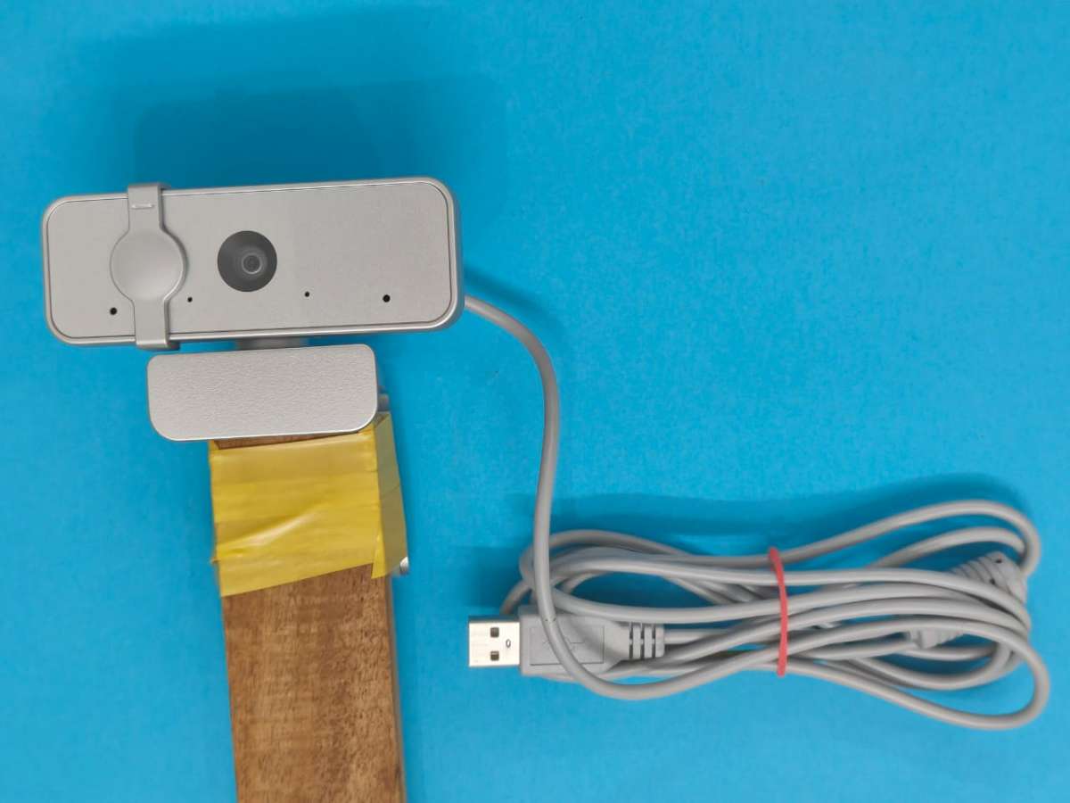
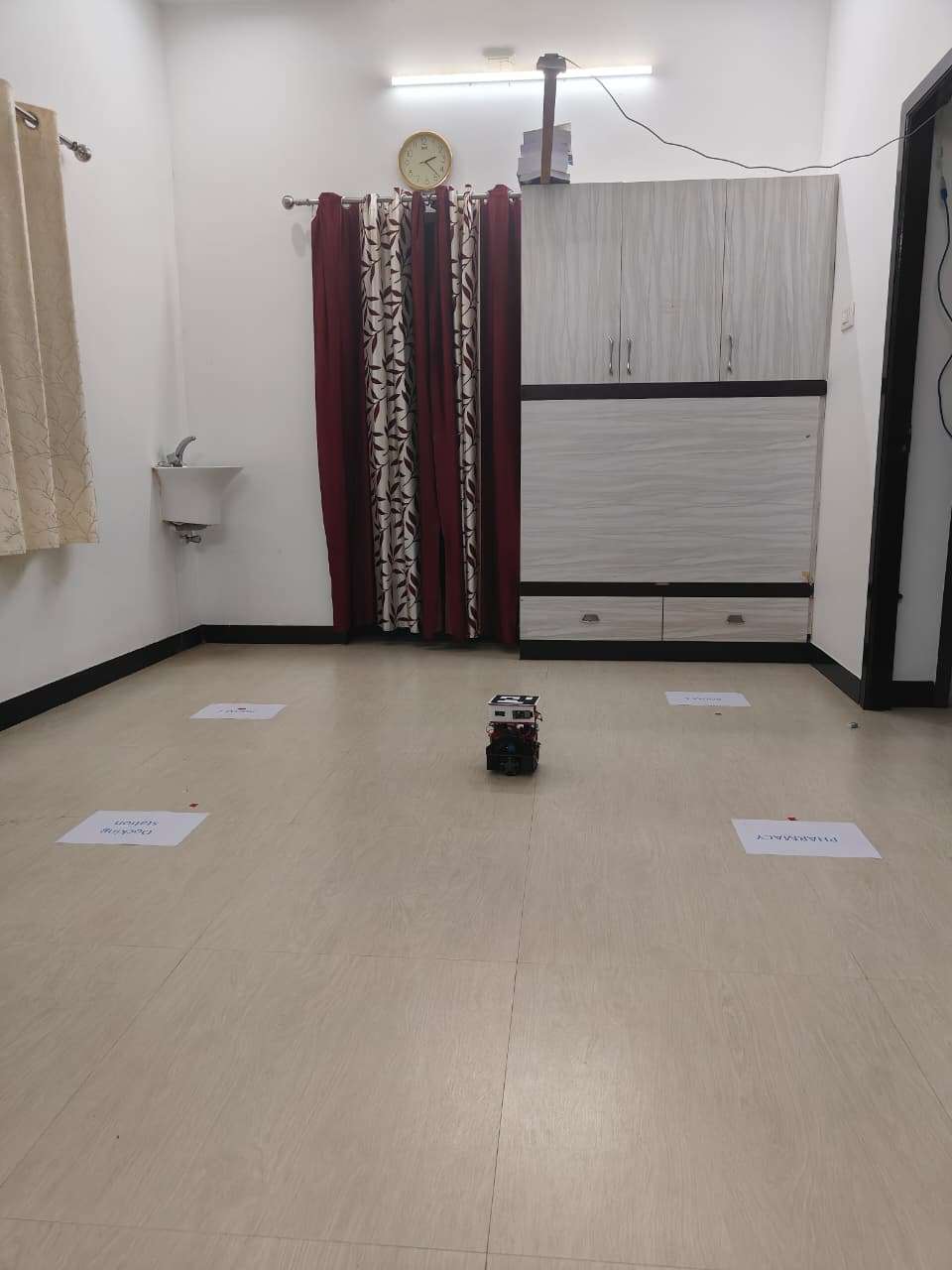
5.1 Mount the Camera
- Fix a USB webcam 1.5m–2m above ground.
- Ensure the ArUco marker on robot is always visible.
5.2 Generate ArUco Marker
- You already have one.
- Print at 5cm × 5cm for accurate pose.
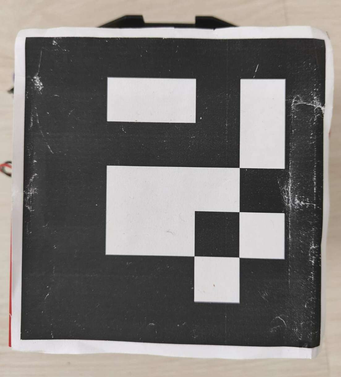
.jpg)
5.3 Flash & Run ArUco Node
File: aruco_pose_publisher.py
#!/usr/bin/env python3
import rclpy
from rclpy.node import Node
from geometry_msgs.msg import PoseStamped
import cv2
import numpy as np
import math
import os

class ArucoPosePublisher(Node):
    def _init_(self):
        super()._init_('aruco_pose_publisher')

        self.pose_pub = self.create_publisher(PoseStamped, '/aruco_pose', 10)

        # --- camera and ArUco parameters ---
        self.cap = cv2.VideoCapture(0)  # change to 1 if second camera
        self.marker_length = 0.05       # marker side (in meters)
        self.aruco_dict = cv2.aruco.getPredefinedDictionary(cv2.aruco.DICT_5X5_50)
        self.parameters = cv2.aruco.DetectorParameters_create()

        # --- load calibration ---
        pkg_dir = os.path.dirname(_file_)
        cam_path = os.path.join(pkg_dir, 'camera_matrix.npy')
        dist_path = os.path.join(pkg_dir, 'dist_coeffs.npy')

        if os.path.exists(cam_path) and os.path.exists(dist_path):
            self.camera_matrix = np.load(cam_path)
            self.dist_coeffs = np.load(dist_path)
        else:
            self.get_logger().warn("⚠ Camera calibration files not found, using default values")
            self.camera_matrix = np.array([[800, 0, 320],
                                           [0, 800, 240],
                                           [0,   0,   1]], dtype=float)
            self.dist_coeffs = np.zeros((5, 1), dtype=float)

        self.timer = self.create_timer(0.1, self.detect_and_publish)
        self.get_logger().info("✅ ArUco Pose Publisher started")

    def detect_and_publish(self):
        ret, frame = self.cap.read()
        if not ret:
            self.get_logger().warn("Camera frame not available")
            return

        gray = cv2.cvtColor(frame, cv2.COLOR_BGR2GRAY)
        corners, ids, _ = cv2.aruco.detectMarkers(gray, self.aruco_dict, parameters=self.parameters)

        if ids is not None:
            rvecs, tvecs, _ = cv2.aruco.estimatePoseSingleMarkers(
                corners, self.marker_length, self.camera_matrix, self.dist_coeffs)

            tvec = tvecs[0][0]
            rvec = rvecs[0][0]
            R, _ = cv2.Rodrigues(rvec)
            yaw = math.atan2(R[1, 0], R[0, 0])

            msg = PoseStamped()
            msg.header.stamp = self.get_clock().now().to_msg()
            msg.pose.position.x = float(tvec[0])
            msg.pose.position.y = float(tvec[1])
            msg.pose.position.z = float(tvec[2])
            msg.pose.orientation.z = float(yaw)

            self.pose_pub.publish(msg)
            self.get_logger().info(f"x={tvec[0]:.2f}m, y={tvec[1]:.2f}m, yaw={math.degrees(yaw):.1f}°")

            cv2.aruco.drawDetectedMarkers(frame, corners)
            cv2.drawFrameAxes(frame, self.camera_matrix, self.dist_coeffs, rvec, tvec, 0.03)

        cv2.imshow("Aruco Detection", frame)
        cv2.waitKey(1)

    def destroy_node(self):
        self.cap.release()
        cv2.destroyAllWindows()
        super().destroy_node()

def main(args=None):
    rclpy.init(args=args)
    node = ArucoPosePublisher()
    try:
        rclpy.spin(node)
    except KeyboardInterrupt:
        pass
    node.destroy_node()
    rclpy.shutdown()

if _name_ == '_main_':
    main()
Run:
ros2 run pharmacy_bot aruco_pose_publisherCheck:
ros2 topic echo /aruco_poseThis gives robot’s x,y,z,yaw coordinates.
Step 6 — Install move_to_goal.py (ROS2 Navigation Node)
This Python node performs:
- Pose smoothing
- Waypoint navigation
- Servo trigger at WP1
- Disinfection trigger at WP2
- Deadzone control
- Smoothing filter
- Speed limiting
Flash & Run ArUco Node
File: move_to_goal.py
#!/usr/bin/env python3
import rclpy
from rclpy.node import Node
from geometry_msgs.msg import PoseStamped, Twist
from std_msgs.msg import Int32
import math
import time

class SmoothTranslateWaypointFollower(Node):
    def _init_(self):
        super()._init_('grid_move_controller')

        # ---------------- PATH ----------------
        self.waypoints = [
            (-0.33, -0.26),  # wp0
            (-0.33, 0.12),   # wp1 (SERVO)
            (0.33, 0.12),    # wp2 (DISINFECT)
            (0.33, -0.22)    # wp3
        ]
        self.loop_path = False

        # ---------------- SETTINGS ----------------
        self.deadzone = 0.02
        self.max_speed = 0.25
        self.kp = 1.2
        self.filter_alpha = 0.40
        self.dwell_secs = 0.5

        # Servo + disinfect settings
        self.servo_wp = 1
        self.servo_wait = 5
        self.servo_done = False

        self.disinfect_wp = 2
        self.disinfect_wait = 10
        self.disinfect_done = False

        # ---------------- INTERNAL STATE ----------------
        self.current_idx = 0
        self._arrived_time = None
        self.smoothed_x = None
        self.smoothed_y = None

        # ---------------- ROS PUB/SUB ----------------
        # subscribe to aruco pose
        self.pose_sub = self.create_subscription(
            PoseStamped, '/aruco_pose', self.pose_callback, 10)

        # send velocity commands to robot (ESP32 board A)
        self.cmd_pub = self.create_publisher(Twist, '/cmd_vel', 10)

        # send servo trigger to master board (ESP32 board B)
        self.servo_pub = self.create_publisher(Int32, '/servo_trigger', 10)

        # send disinfect timer to master board (ESP32 board B -> TM1637)
        self.display_pub = self.create_publisher(Int32, '/display_number', 10)

        self.get_logger().info("Robot navigation started.")
        self.print_path()

    def print_path(self):
        self.get_logger().info(f"Path length: {len(self.waypoints)} waypoints")
        for i, (x, y) in enumerate(self.waypoints):
            self.get_logger().info(f"  WP{i}: x={x:.3f}, y={y:.3f}")

    def stop_robot(self):
        # publish explicit zero floats to avoid C-level conversion issues
        cmd = Twist()
        cmd.linear.x = 0.0
        cmd.linear.y = 0.0
        cmd.angular.z = 0.0
        try:
            self.cmd_pub.publish(cmd)
        except Exception as e:
            self.get_logger().error(f"Failed to publish stop cmd: {e}")

    def _publish_servo(self):
        if self.servo_done:
            return
        msg = Int32()
        msg.data = 1
        try:
            self.servo_pub.publish(msg)
            self.get_logger().info("🟠 /servo_trigger published (servo start)")
        except Exception as e:
            self.get_logger().error(f"Failed to publish /servo_trigger: {e}")
        self.servo_done = True

    def _publish_disinfect_timer(self):
        if self.disinfect_done:
            return
        msg = Int32()
        msg.data = int(self.disinfect_wait)
        try:
            self.display_pub.publish(msg)
            self.get_logger().info(f"🟣 /display_number published ({msg.data})")
        except Exception as e:
            self.get_logger().error(f"Failed to publish /display_number: {e}")
        self.disinfect_done = True

    def pose_callback(self, msg: PoseStamped):
        # finished?
        if self.current_idx >= len(self.waypoints):
            self.stop_robot()
            return

        # read raw pos
        raw_x = msg.pose.position.x
        raw_y = msg.pose.position.y

        # smoothing init
        if self.smoothed_x is None:
            self.smoothed_x = raw_x
            self.smoothed_y = raw_y

        a = self.filter_alpha
        self.smoothed_x = a * self.smoothed_x + (1.0 - a) * raw_x
        self.smoothed_y = a * self.smoothed_y + (1.0 - a) * raw_y

        x = float(self.smoothed_x)
        y = float(self.smoothed_y)

        wp_x, wp_y = self.waypoints[self.current_idx]
        dx = float(wp_x - x)
        dy = float(wp_y - y)
        dist = math.hypot(dx, dy)

        # ARRIVED
        if dist <= self.deadzone:
            # ensure robot stopped
            self.stop_robot()

            if self._arrived_time is None:
                # first arrival at this waypoint -> record time and trigger events
                self._arrived_time = time.time()
                self.get_logger().info(f"ARRIVED at WP{self.current_idx}")

                if self.current_idx == self.servo_wp:
                    # trigger servo
                    self._publish_servo()

                if self.current_idx == self.disinfect_wp:
                    # trigger disinfect timer/LED
                    self._publish_disinfect_timer()

                return

            # still dwelling: check how long we have waited
            waited = time.time() - self._arrived_time

            # if at servo WP, wait servo_wait seconds before moving on
            if self.current_idx == self.servo_wp:
                remaining = self.servo_wait - waited
                if remaining > 0:
                    self.get_logger().info(f"🟠 Waiting for servo: {int(remaining)}s left")
                    return

            # if at disinfect WP, wait disinfect_wait seconds before moving on
            if self.current_idx == self.disinfect_wp:
                remaining = self.disinfect_wait - waited
                if remaining > 0:
                    self.get_logger().info(f"🟣 DISINFECT → {int(remaining)}s left")
                    return

            # done waiting -> move to next waypoint
            self._arrived_time = None
            self.current_idx += 1
            self.get_logger().info(f"➡ Advancing to WP{self.current_idx}")
            return

        # NORMAL MOVEMENT - proportional control
        vx = float(self.kp * dx)
        vy = float(self.kp * dy)

        mag = math.hypot(vx, vy)
        if mag > self.max_speed and mag > 1e-9:
            scale = float(self.max_speed / mag)
            vx *= scale
            vy *= scale

        # small deadband to avoid jitter
        if abs(vx) < 0.01:
            vx = 0.0
        if abs(vy) < 0.01:
            vy = 0.0

        # publish Twist with explicit floats
        cmd = Twist()
        cmd.linear.x = float(vx)
        cmd.linear.y = float(vy)
        cmd.angular.z = 0.0

        try:
            self.cmd_pub.publish(cmd)
        except Exception as e:
            self.get_logger().error(f"Failed to publish /cmd_vel: {e}")

        self.get_logger().info(
            f'wp={self.current_idx} target=({wp_x:.3f},{wp_y:.3f}) pos=({x:.3f},{y:.3f}) dx={dx:.3f} dy={dy:.3f} → MOVE'
        )


def main(args=None):
    rclpy.init(args=args)
    node = SmoothTranslateWaypointFollower()
    try:
        rclpy.spin(node)
    except KeyboardInterrupt:
        pass
    node.destroy_node()
    rclpy.shutdown()


if _name_ == "_main_":
    main()
Run:
ros2 run pharmacy_bot move_to_goal
Check:
ros2 topic echo /cmd_vel
ros2 topic echo /display_number
ros2 topic echo /servo_trigger
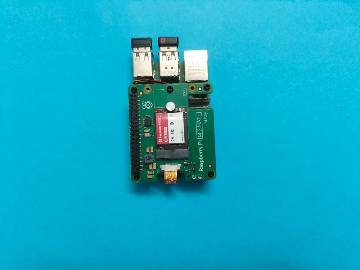
Step 7 — micro-ROS Agent Setup
On Ubuntu / Raspberry Pi run:
ros2 run micro_ros_agent micro_ros_agent udp4 --port 8888