




Aim and scope of the Project:
The main aim of this project is to design a Voice Controlled Candy Bot using an Arduino UNO and Bluetooth communication. The bot responds to voice commands received from a smartphone application and displays different emotions and actions using an RGB LED. This project demonstrates wireless communication, voice-based control, embedded systems programming and human-machine interaction.
The system provides an interactive platform where users can control the bot through simple voice commands. It helps students understand Bluetooth communication, Arduino programming, RGB LED control and mobile-based automation. The project can be extended for smart toys, educational robots, assistive devices and interactive robotic systems.
1. Construction of the Project
This project is implemented using an Arduino UNO, HC-05 Bluetooth module, RGB LED and a smartphone running the Arduino Bluetooth Connect application. The present project can be done with any Arduino Board but due to basic level learner's the Arduino UNO is used in the project.
Components Required
| Component | Purpose |
|---|---|
| Arduino UNO | Main controller |
| HC-05 Bluetooth Module | Wireless communication |
| RGB LED (Common Cathode) | Emotion indication |
| 220 Ω Resistors (3 Nos.) | Current limiting |
| Breadboard | Circuit assembly |
| Connecting Wires | Interconnections |
| Smartphone | Voice command input |
| Arduino Bluetooth Connect App | Voice control interface |
Pin Connections
The following table shows the component/device connections to Arduino UNO board pins.
| Arduino UNO Pin | Connected Device | Function |
|---|---|---|
| D2 | RGB LED Red Pin | Anger indication |
| D3 | RGB LED Green Pin | Happy indication |
| D4 | RGB LED Blue Pin | Sad indication |
| D10 | HC-05 TX | Bluetooth communication |
| D11 | HC-05 RX | Bluetooth communication |
| 5V | HC-05 VCC | Power supply |
| GND | HC-05 GND | Common ground |
Circuit Design and Construction
After collecting the required components, the circuit is assembled according to the circuit diagram designed with Cirkit Designer software.
.png)
The HC-05 Bluetooth module is connected to the Arduino UNO through Software Serial communication using Rx on Bluetooth pins to Arduino D11 pin for Tx and Tx on Bluetooth to Arduino pin D10 for Rx. Hardware serial connection on Arduino can use but I used software serial communication for this project.
RGB LED with Common cathode:
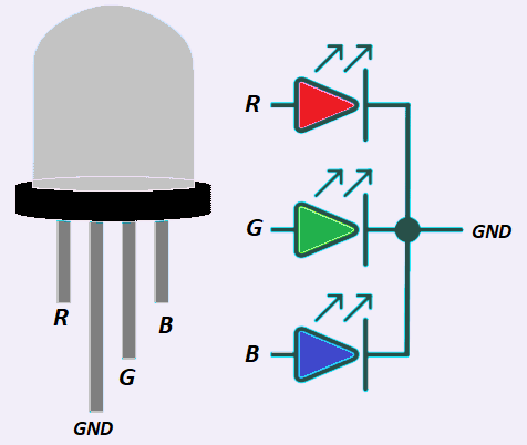
The RGB LED is connected through current-limiting resistors to protect the LED from excessive current. Arduino hardware D2 pin is connected to RED pin, D3 pin is connected to GREEN pin and D4 pin is connected to BLUE pin. The RGB LED can be common anode or cathode type, in current project it is common cathode type used and it is connected to GND.
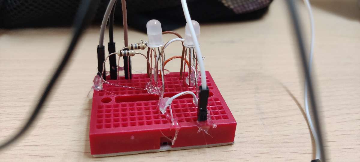
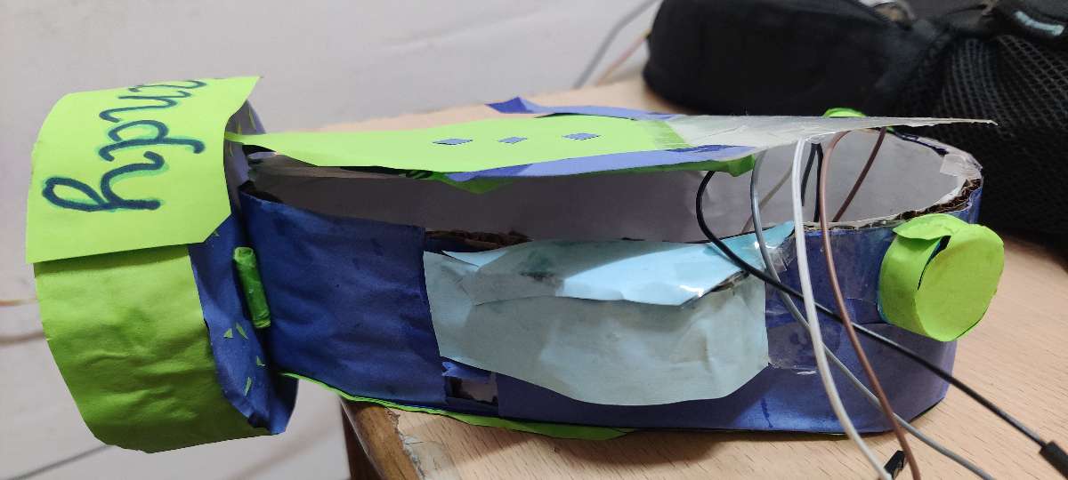
The complete physical hardware with connections is placed inside the dancing toy as shown in the figure below.
The smartphone is paired with the HC-05 Bluetooth module. Voice commands spoken through the Arduino Bluetooth Connect application are converted into text and transmitted wirelessly to the Arduino UNO.
The Arduino continuously monitors the incoming Bluetooth data and performs the corresponding action based on the received command.
2. Programming
Flow Chart
The following flow chart illustrates the working logic of the Voice Controlled Candy Bot.
	Start System
		↓
Initialize Bluetooth Module
		↓
Wait for Voice Command
		↓
Receive Command from Smartphone
		↓
  Compare Command
		↓
 Anger → RED LED ON
 Happy → GREEN LED ON
   Sad → BLUE LED ON
 Dance → RGB Color Sequence
 Take rest → LEDs OFF
Wake Up → WHITE Color
		↓
Repeat Continuously
Arduino Program
The Arduino IDE is used to write, compile, and upload the program into the Arduino UNO board.
The program receives Bluetooth commands from the HC-05 module and controls the RGB LED according to the selected emotion or action. The Mobile app ARDUINO BLUETOOTH CONNECT APP is available in play for Android Version from URL https://play.google.com/store/apps/details?id=com.giristudio.hc05.bluetooth.arduino.control download and install in the Android Smartphone.
The Smartphone Bluetooth is enabled and scan to appear the exact Bluetooth device to pair and connect.
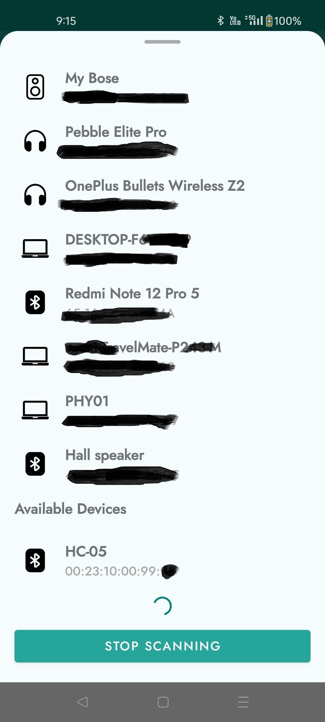
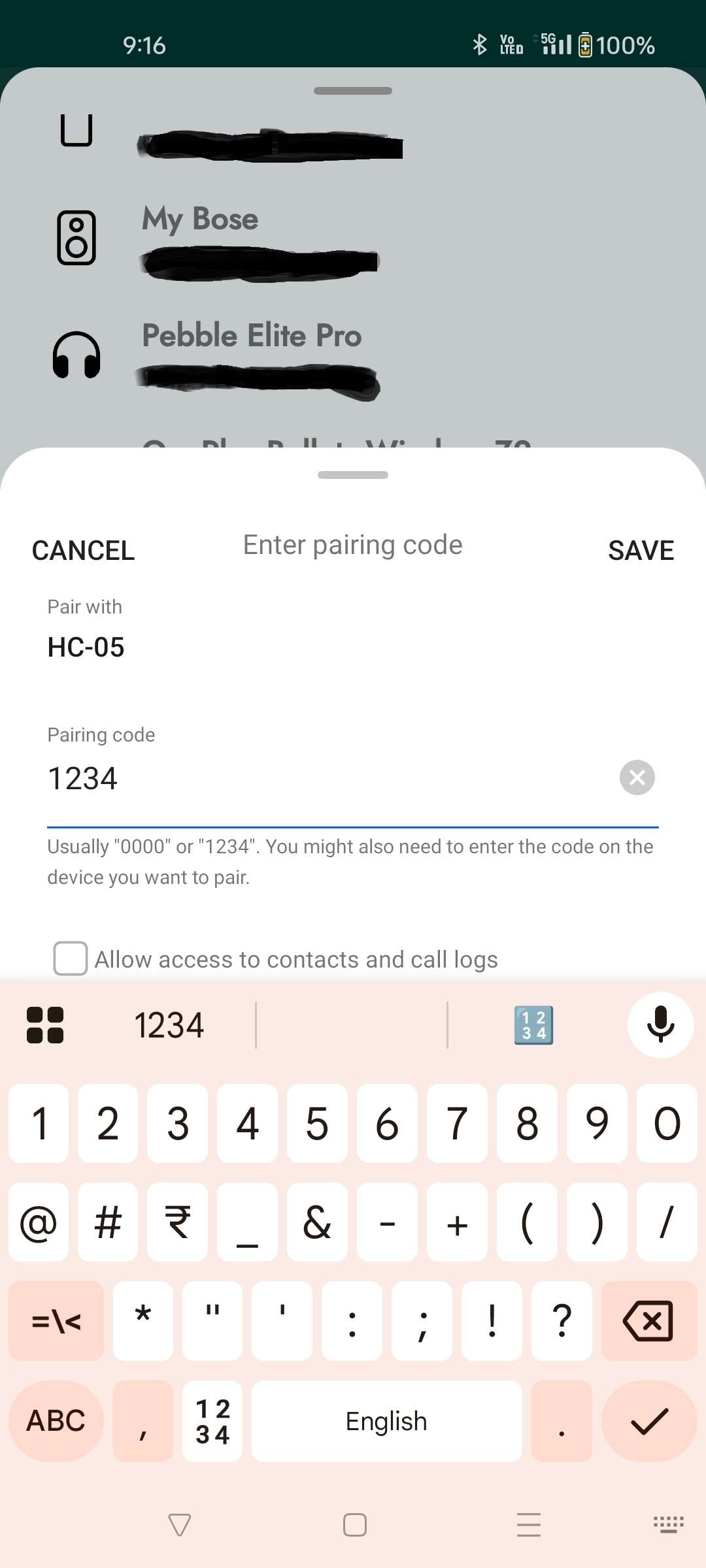
Scan and pair the Project device with default pairing code in Smartphone as follows to establish connection.
After the pairing open the Arduino Bluetooth connect app it will show available gadgets in the app. In the current project we are using Voice Terminal. If the connection is establish it shows GREEN mark or else it will be RED disconnection logo in app.
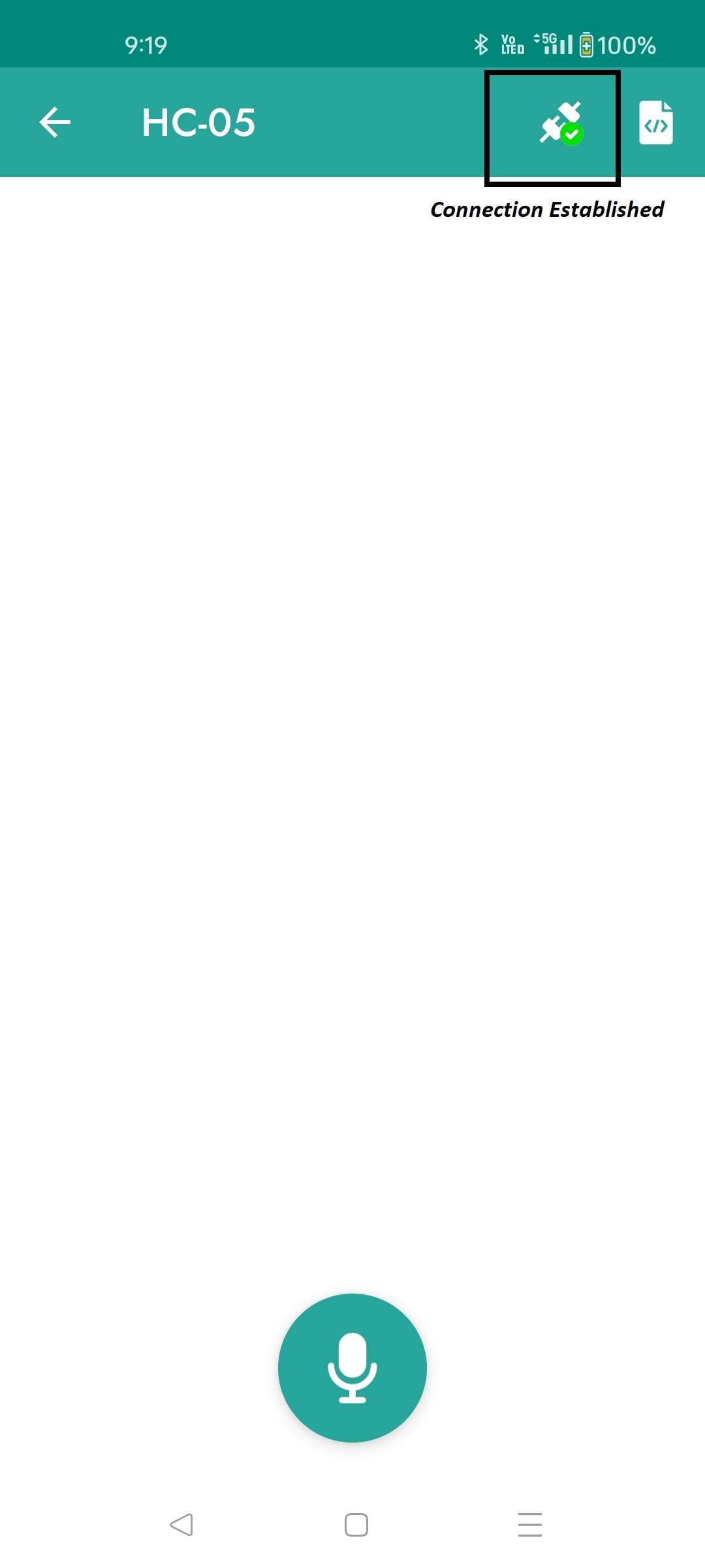
Hold-on the Voice button on the app and speak with google voice it will interact with Project hardware kit and then action will be performed on the Hardware kit.
Supported Voice Commands: With the App voice commands the hardware kit respond accordingly in wireless communication.
• Candy show Anger
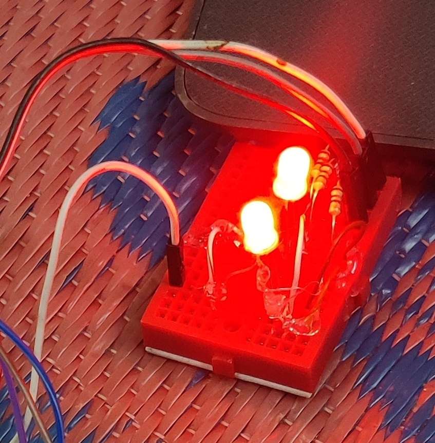
• Candy show Sad
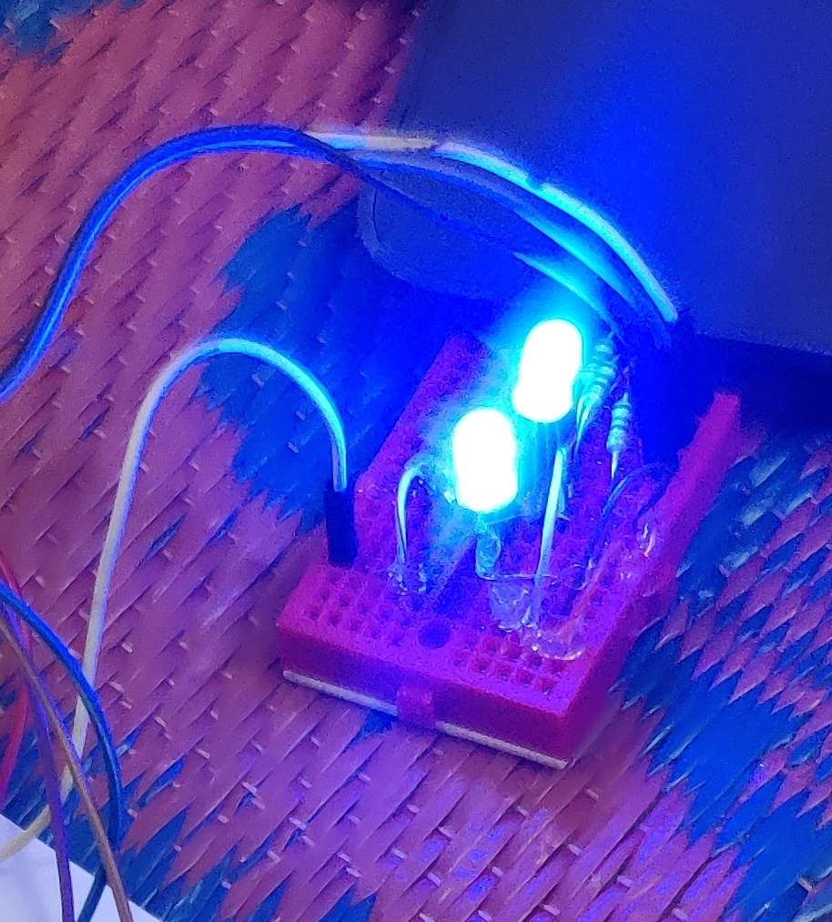
• Candy show Happy
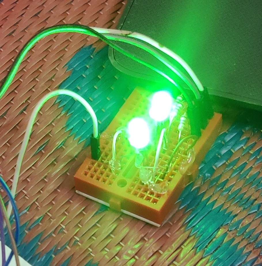
• Candy Dance Mode

• Candy Wake Up
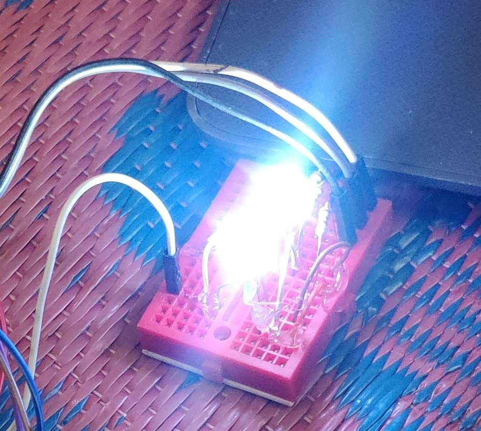
• Candy Take Rest
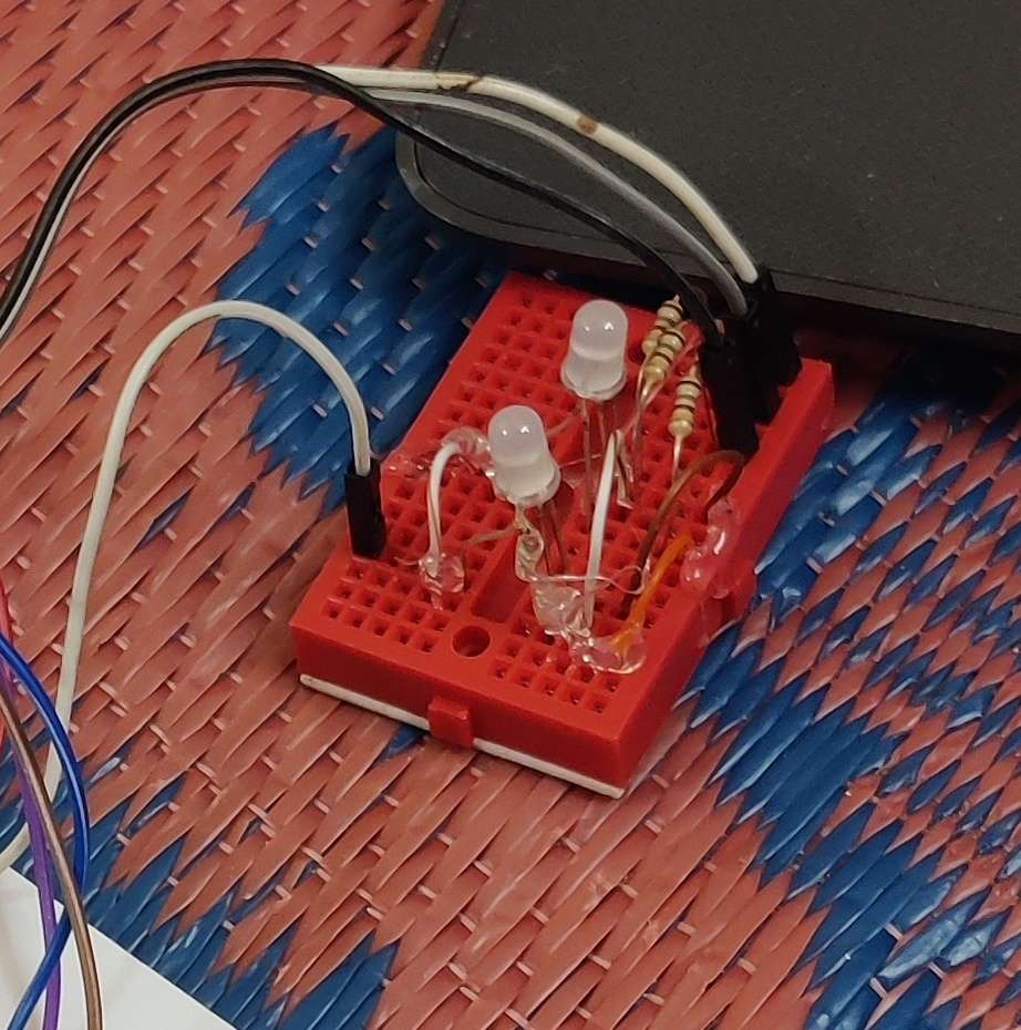
The complete Arduino program is provided in the source code section below.
#include <SoftwareSerial.h>
String value;

int TxD = 11;
int RxD = 10;

const int redPin = 2;
const int greenPin = 3;
const int bluePin = 4;

SoftwareSerial bluetooth(TxD, RxD);

void setColor(bool r, bool g, bool b)
{
  digitalWrite(redPin, r);
  digitalWrite(greenPin, g);
  digitalWrite(bluePin, b);
}

void setup()
{
  pinMode(redPin, OUTPUT);
  pinMode(greenPin, OUTPUT);
  pinMode(bluePin, OUTPUT);
  Serial.begin(9600);
  bluetooth.begin(9600);
  setColor(0, 0, 0);
}

void loop()
{
  if (bluetooth.available())
  {
    value = bluetooth.readString();
    value.trim();
    value.toLowerCase();
    Serial.println(value);

    // ANGER = RED
    if (value == "candy show anger")
    {
      setColor(1, 0, 0);
      Serial.println("Angry Mode");
    }

    // HAPPY = GREEN
    else if (value == "candy show happy")
    {
      setColor(0, 1, 0);
      Serial.println("Happy Mode");
    }

    // SAD = BLUE
    else if (value == "candy show sad")
    {
      setColor(0, 0, 1);
      Serial.println("Sad Mode");
    }

    // TAKE REST = OFF
    else if (value == "candy take rest")
    {
      setColor(0, 0, 0);
      Serial.println("Sleep Mode");
    }

    // WAKE UP = WHITE
    else if (value == "candy wake up")
    {
      setColor(1, 1, 1);
      Serial.println("Wake Up Mode");
    }

    // DANCE = MULTICOLOR EFFECT
    else if (value == "candy dance mode")
    {
      Serial.println("Dance Mode");

      for (int i = 0; i < 3; i++)
      {
        setColor(1, 0, 0);  // Red
        delay(300);
        setColor(0, 1, 0);  // Green
        delay(300);
        setColor(0, 0, 1);  // Blue
        delay(300);
        setColor(1, 1, 0);  // Yellow
        delay(300);
        setColor(0, 1, 1);  // Cyan
        delay(300);
        setColor(1, 0, 1);  // Magenta
        delay(300);
        setColor(1, 1, 1);  // White
        delay(300);
      }
    }
  }
}
3. Execution and Operation
The Arduino program is uploaded using the Arduino IDE.
After uploading:
- Power ON the Arduino UNO.
Open the Arduino Bluetooth Connect application in Smartphone App
.jpg)
Pair the smartphone with the HC-05 Bluetooth module
Check the Connect is establish in the App.
.jpg)
Press the Voice Command button.
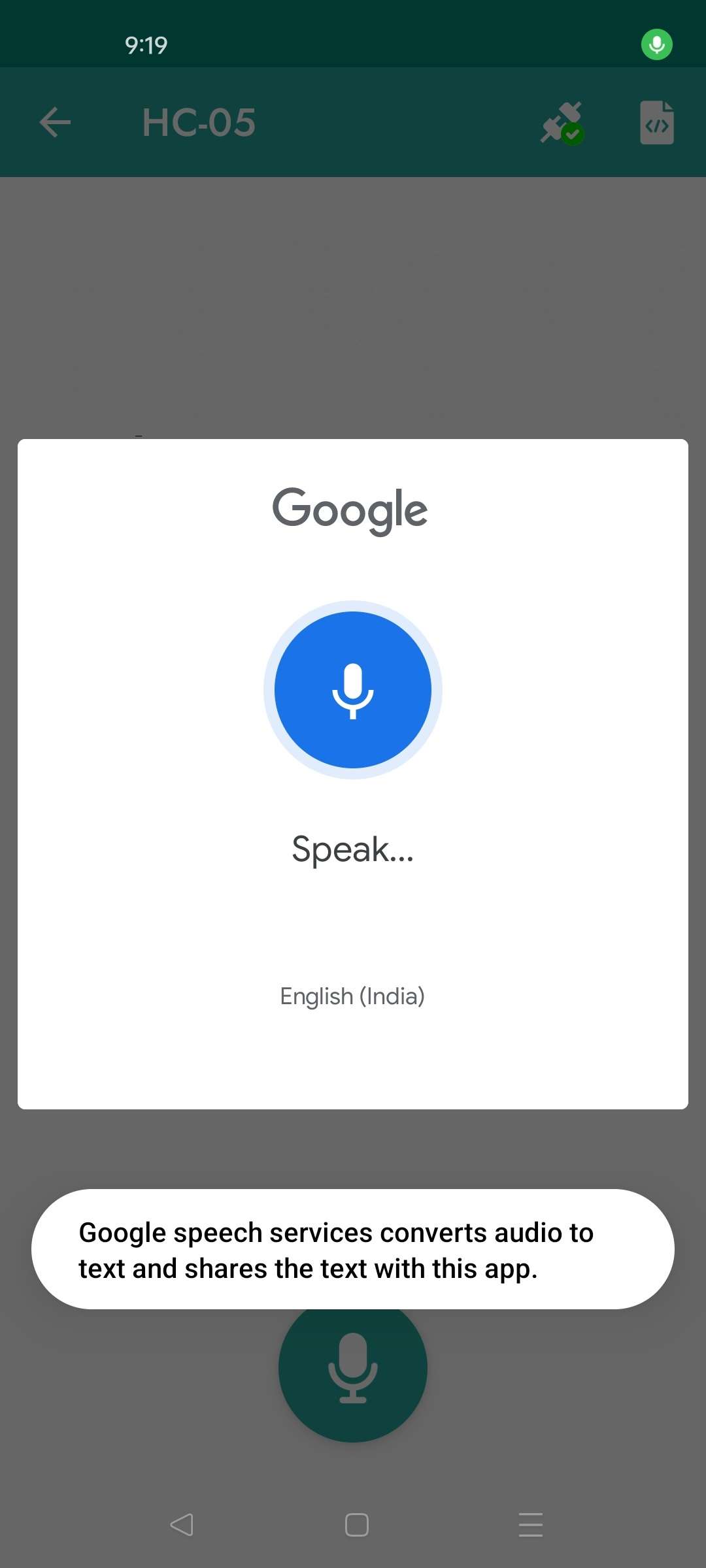
Speak any supported command.
.jpg)
The Arduino receives the command and immediately updates the RGB LED according to the selected emotion.
Emotional Responses
• candy show Anger → Red Color
• candy show Happy → Green Color
• candy show Sad → Blue Color
• candy Dance mode → Multiple Color Animation
• candy Take Rest → All LEDs OFF
• candy Wake Up → White Color
This creates an interactive Candy Bot capable of expressing emotions using color patterns.
4. Video Demonstration
The operation of the Voice Controlled Candy Bot is demonstrated through the attached video. The video shows how voice commands received through Bluetooth are processed by the Arduino UNO to generate different emotional states and actions using the RGB LED.
The demonstration highlights real-time wireless control, Bluetooth communication, and emotion-based visual interaction between the user and the Candy Bot.
Applications
The current project device is useful in different applications like
• Smart Toys
• Educational Robotics
• Interactive Learning Systems
• Human-Machine Interface Projects
• Bluetooth-Based Automation
• Smart Home Demonstrations
• STEM Education Projects
Future Enhancements
The project can be further enhanced by:
• Adding servo motors for facial movement.
• Integrating sound effects and speech responses.
• Using OLED displays for animated expressions.
• Implementing AI-based emotion recognition.
• Adding IoT connectivity for remote operation.
• Integrating gesture recognition systems.
Conclusion
The Voice Controlled Candy Bot successfully demonstrates a Bluetooth-based interactive robotic system using Arduino UNO. The project receives voice commands from a smartphone and responds by displaying different emotions and actions through an RGB LED. The implementation provides an effective demonstration of wireless communication, embedded systems programming and human-machine interaction.
The project is simple, low-cost and easy to implement while offering an engaging user experience. It serves as an excellent educational platform for learning Arduino programming, Bluetooth communication and voice-controlled automation. With additional sensors and intelligent algorithms, the system can be extended into advanced social robots, smart assistants and interactive robotic applications.