I-Mage — a handheld, offline retinal camera that screens for diabetic and hypertensive retinopathy
1. The problem
India has two of the world's largest chronic disease burdens at the same time. The 2023 ICMR-INDIAB study put diabetes at about 101 million adults. The number with hypertension is higher, near 315 million. Many of those cases are never diagnosed, mostly among people who live far from a hospital.
Both diseases leave marks on the retina. Diabetic retinopathy (DR) damages the small blood vessels of the retina. Hypertensive retinopathy (HR) shows up as narrowed arterioles, nicked veins, cotton wool spots and small haemorrhages caused by sustained high blood pressure. The retina is the one place in the body where these vessels can be seen directly, without surgery. It reflects the state of the vessels in the heart, brain and kidneys, and some hypertensive changes appear there before blood pressure is ever measured. Both retinopathies can blind a person, and both follow the same rule: caught early they are treatable, caught late the damage is permanent. The SMART India study found DR in about 12.5% of people with diabetes, and the sight threatening form in 4%, with no real difference between cities and villages.
The diseases are everywhere. The screening is not. A retinal exam needs an ophthalmologist or a trained grader and a fundus camera, and both sit in cities. National screening is mostly opportunistic and urban, so rural patients are left out. There are not enough eye specialists to examine every person with diabetes or hypertension. The usual answer is a mobile screening van, which helps but does not scale, because the imaging equipment in one van can cost around 1 crore rupee. So the people most likely to go undiagnosed are exactly the ones a yearly retinal check would help most.
What is missing is a way to screen that needs no specialist on site, no internet, and no hospital budget. That is what I-Mage is for. It is a handheld device that photographs the retina and grades the image on the device itself, offline, in a few seconds, for both diabetic and hypertensive retinopathy. It costs about ₹12,000 to build.
2. Why existing tools leave a gap
Point of care retinal screening already exists and works. Peek Vision's phone adapter brought fundus imaging onto a smartphone, though its own makers say it suits the optic nerve better than confident DR screening. Optomed sells the Aurora, a standalone handheld camera that can show a DR result on its own screen. In Bengaluru, Remidio pairs its Fundus on Phone camera with Medios AI, which in 2019 became the first DR algorithm to run fully offline on the device with no internet, and now also flags glaucoma and AMD. It is validated at about 93% sensitivity for referable DR. On device retinal AI is a solved, deployed idea, and we do not claim to have invented it.
What none of them solved is cost and access. Each one is a commercial, regulated medical product priced for institutions. The phone based systems need a proprietary handset and app. The standalone cameras sell by quotation or on multi year lease. They made retinal screening portable. They did not make it cheap enough to put in every primary health centre, every diabetes camp and every rural sub centre in a country with over 100 million people with diabetes and 300 million with hypertension.
That gap, unit cost and closed hardware, is what I-Mage attacks. The goals were narrow on purpose: run on its own with no phone, no PC and no cloud; screen for both diabetic and hypertensive retinopathy from one image; use only off the shelf parts anyone can buy; and come in an order of magnitude below commercial systems. Built around a Raspberry Pi 4, whose board costs about ₹5,500 against the ₹13,600 of the Pi 5 we prototyped on, the whole device lands near ₹12,000. I-Mage is not a rival to a validated, approved camera, and we will not pretend it is. It is a proof of something simpler: that the core capability can be rebuilt openly and cheaply enough to change who can own one.
That last point sets up the rest of this build. The grading model is the easy part. Offline retinal inference is well understood, as Remidio showed years ago. The hard part, on a ₹12,000 budget, is capturing a usable retinal image at all: the optics, the lighting, the alignment. That is what most of this build is about.
3. Bill of materials
For the recommended Pi 4 build. Prices are indicative, in rupees.
| Item | Part | Qty | ₹ |
|---|---|---|---|
| Compute | Raspberry Pi 4 (4 GB) | 1 | 5,546 |
| Imaging | Pi Camera Module 2 (IMX219, 8 MP) | 1 | 1,698 |
| Display | 2.2" ILI9341 SPI TFT (240×320) | 1 | 645 |
| Input | Tactile push buttons | 4 | 17 |
| Input | Perfboard, button ground rail | 1 | 30 |
| Wiring | Dupont jumpers, female to female | 1 set | 167 |
| Wiring | Dupont jumpers, male to female | 1 set | 85 |
| Light power | 18650 cell, Samsung INR18650-30Q | 2 | 1,156 |
| Light power | 2×18650 switched holder | 1 | 39 |
| Light power | XL6009 boost converter | 1 | 57 |
| Light power | Dual slot 18650 Li-ion charger | 1 | 289 |
| Lighting | 12 V 5730 LED module | 1 | 19 |
| Optics | 20D double aspheric lens | 1 | 1,189 |
| Storage | microSD card, 32 GB | 1 | 1,399 |
| Total | ~12,336 |
The Pi runs from any 5 V, 3 A phone charger with a USB-C lead, so it is not on the list. The LED module is sold only in a pack of 20 at ₹385, of which one is used, so it costs about ₹19 per build. The prototype used a Pi 5 8 GB (₹13,599) with the official active cooler (₹488) and a Pi 5 camera adapter cable (₹107), which puts the as-built device near ₹20,000.
4. How it works
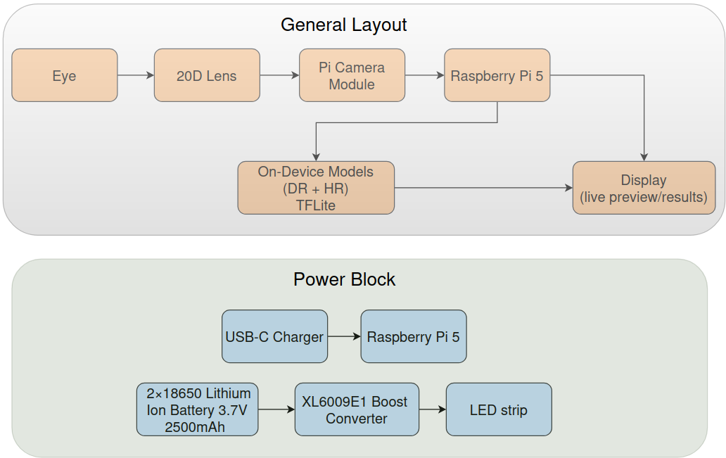
I-Mage is one handheld, 3D printed unit that holds everything needed to photograph the back of the eye and read it. Inside are the optics (a 20D ophthalmic lens), a Raspberry Pi camera, a 2.2 inch screen, four buttons, an LED for lighting, and a Raspberry Pi that runs the whole pipeline on board. There is no phone, no laptop and no internet at any point. The operator holds it to the patient's eye, lines up the retina on the screen, presses a button, and a few seconds later the screen shows a screening result for diabetic and hypertensive retinopathy.
The operator sees a simple five step flow:
- Boot. The device powers up and loads its models.
- Align. A live camera preview lets the operator centre and focus the retina.
- Review. The captured frame is shown to accept or retake, so that a blurry or dark image is caught here instead of being graded later.
- Analyse. The accepted image is graded on the device.
- Results. The grade is shown on screen.
The whole loop runs offline on the Pi. That is the point of the device: a self contained screener that needs only power, returns a result on the spot, and costs about ₹12,000 to build. Under that simple flow sit the parts that were hard to get right on a small budget: the optics that form the image, the camera and display that have to feel responsive, the models that grade the image, and the app that ties them together. The rest of this build goes through each, starting with the hardest one, getting a usable retinal image.
5. The optics
This is the hard part of the build, and the part a ₹12,000 budget makes interesting. Photographing the retina means imaging a small curved surface deep inside the eye, through the pupil, without the light bouncing off the cornea straight back into the lens. Commercial cameras solve this with custom optics. We had to do it with one off the shelf ophthalmic lens.
The principle
I-Mage uses the optics of indirect ophthalmoscopy. A 20 dioptre double aspheric lens, the kind an eye doctor holds at a slit lamp, sits at the front of the device about one focal length (near 5 cm) from the eye. Light is shone through the pupil to illuminate the retina. The lens collects the returning light and forms a real, inverted image of the retina in the air behind it. The Raspberry Pi camera, set back in the tube, focuses on that floating image and photographs it. It is the same method used in smartphone fundus photography, with the phone replaced by the Pi camera. The inverted image is flipped back in software.
.jpeg)
20 D Double Aspheric Lens
The build
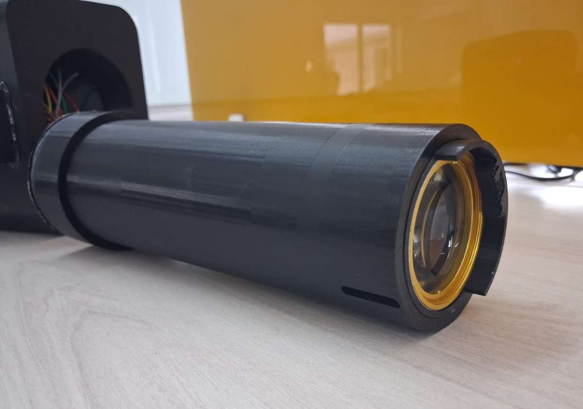
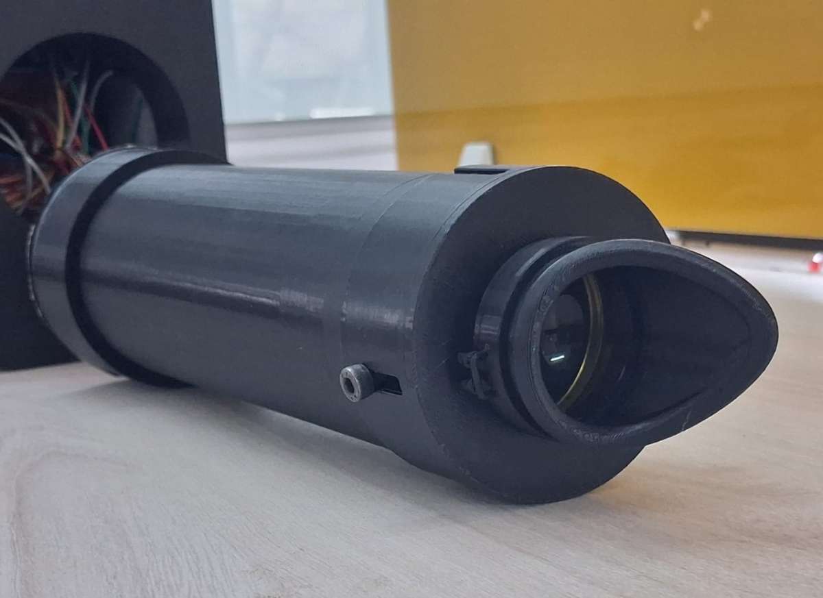
The 20D lens sits at the front of a long 3D printed tube, with the camera at the far end inside the body, looking straight down the tube through the lens. The tube length fixes the lens to camera distance. At the very front is a molded eyecup the patient rests against. It does two jobs: it sets a fixed working distance from the eye to the lens, so the operator is not hunting for the right standoff, and it blocks ambient light, so the only light reaching the sensor comes back through the lens. The eye is lit by the 12 V LED. The inside of the tube is matte black for the same reason.
.jpeg)
3D printed tube containing 20D lens and molded eyecup at the front
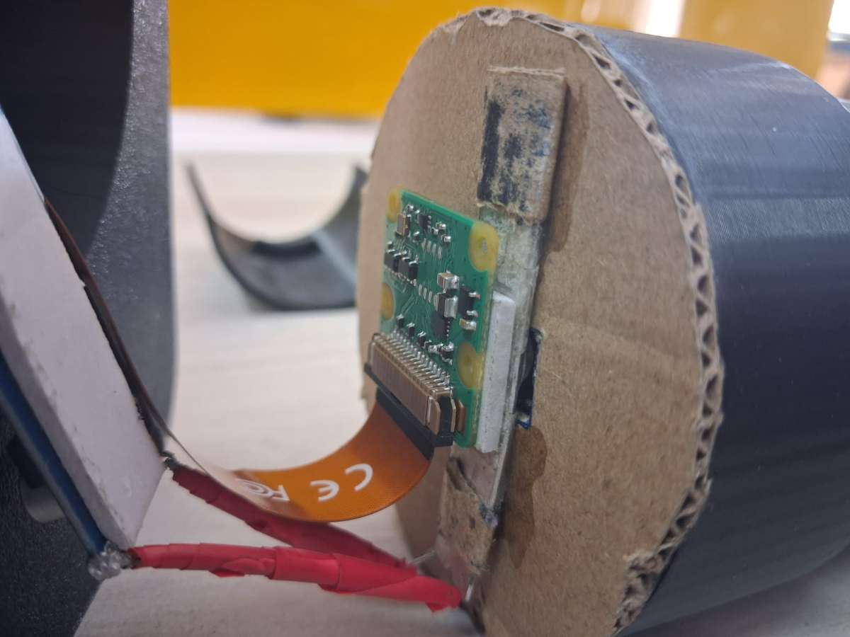
Camera and LED strip at the back
According to theory, the fixed distances of the apparatuses should work, but reality doesn't leave us so easily. So to adapt to ourselves to these we have introduced a mechanism of tilting and sliding of the lens incase due to difference in the eye socket of different patients or incase we need to change the lens due to some damages, we could change them to adjust to the new distances required. Here is how it works, the eyecup is of two parts which contains ridges separated by the distance equal to the length of the lens, so that the lens could rest upon it when the two parts are joined together.
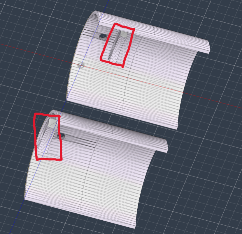
Ridges present in the lens holder
Lens secured in place with the help of the ridges when the two halves are joined in this way
As the two parts of the holder are separate, they can be moved. When the one part of the holder is kept stationary and other is moved in different directions, the lens will tilt backwards or frontward. And also if, both the parts are moved together, then the lens could be moved inside the optical tube.
Lens tilt reduces internal reflections, thus we thought having this feature is necessary. And in case of, the lens needs to be moved a bit towards the eye, this mechanism accommodates that too.
6. Hardware and imaging
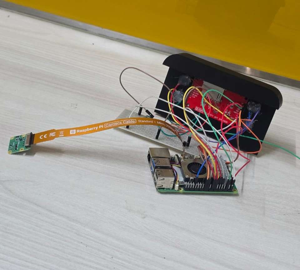
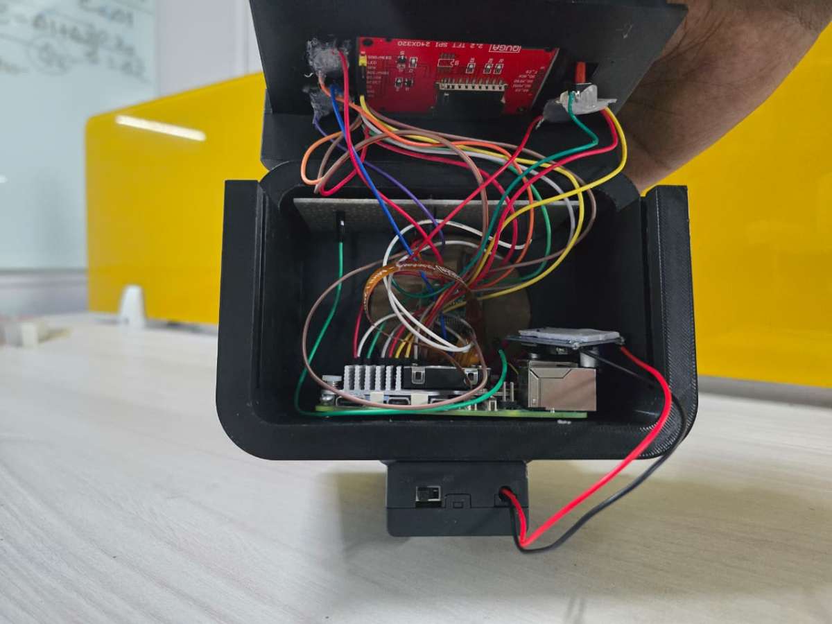
I-Mage has no custom electronics. Every part is an off the shelf module, wired together with jumper leads. That is on purpose. It keeps the cost down, lets anyone with the same parts list rebuild it, and means there is no board to fabricate. The price is the loom of wiring inside, which you can see in the build photos. A neater version would move everything onto one carrier board, but nothing about the function needs it.
.png)
Compute and imaging
The brain is a Raspberry Pi: a Pi 5 in the prototype with the official active cooler, a Pi 4 in the recommended build, for the reasons in the engineering decisions section. Imaging uses a Raspberry Pi Camera Module 2, the standard 8 megapixel IMX219 sensor, connected through the Pi's camera port and pointed up the tube to photograph the retina through the 20D lens. It is an ordinary consumer camera doing an unusual job. The optics that make that possible are in the previous section.
.jpeg)
RPi 5 with cooler
.jpeg)
RPi 5 with the Pi camera module 2
Display and controls
Output is a 2.2 inch ILI9341 TFT (240x320) over SPI. How it is driven fast enough for a live preview is the next section. Input is four push buttons on the Pi's GPIO header, sharing a common ground on a small perfboard rail. The display and those four buttons are everything the operator touches.
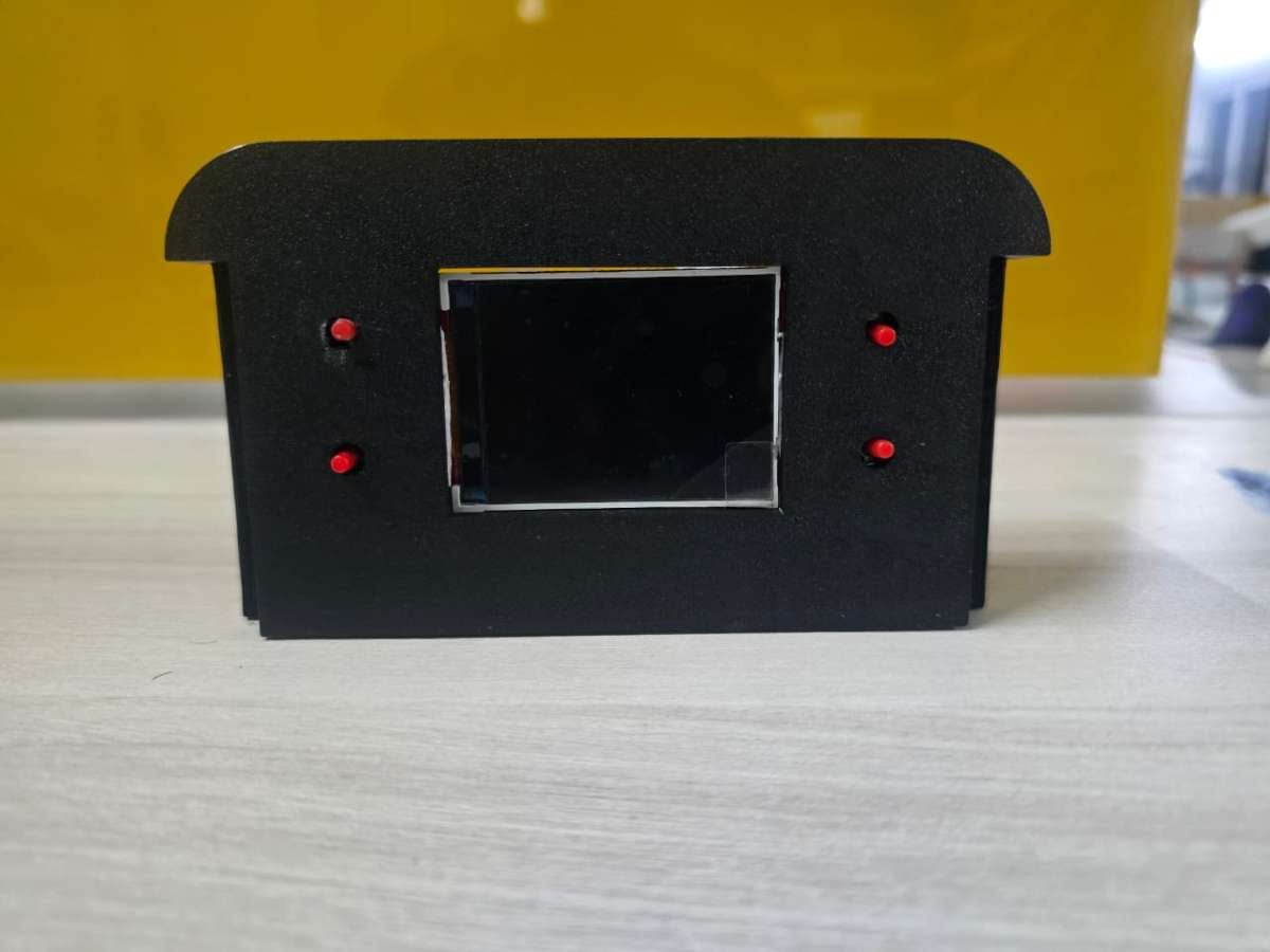
2.2 inch TFT display and push buttons fitted onto 3D printed casing (Front View)
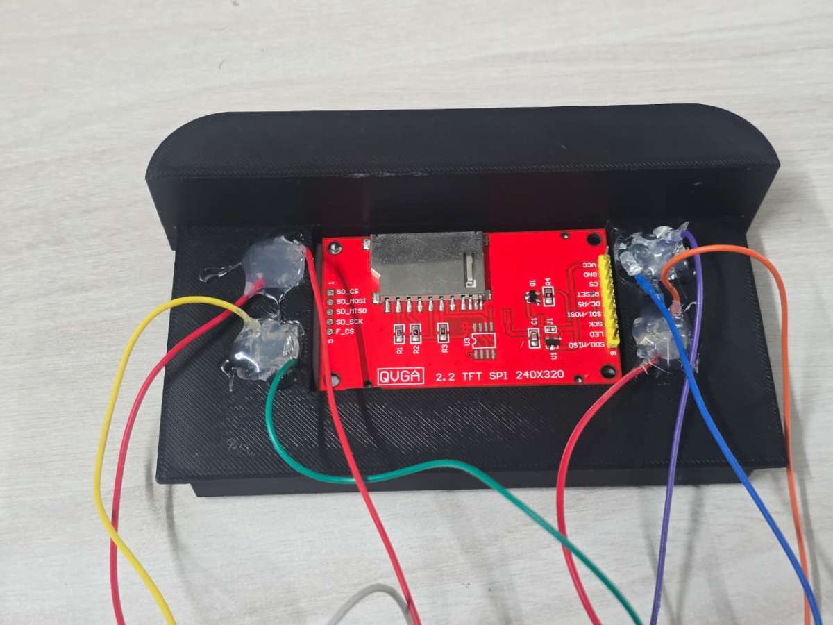
2.2 inch TFT display and push buttons fitted onto 3D printed casing (Back View)
.jpeg)
Common Ground connections using a perfboard rail
Power
The device runs on two separate supplies. The Pi runs from a USB-C charger, a stable source with none of the trouble that comes from running a Pi off a boosted battery. The lighting has its own supply: two 18650 lithium cells stepped up through an XL6009 converter to drive the 12 V LED, switched on and off at the battery holder. Keeping the bright, current hungry light off the Pi's supply is a deliberate choice, covered in the engineering decisions section. Where the LED sits optically is covered in the optics section.
.jpeg)
Samsung Li-ion 18650 batteries and 18650 Battery Holder with switch
.jpeg)
XL6009 Boost Converter
.jpeg)
LED strip
7. The display pipeline
The screen is a 2.2 inch, 240x320 ILI9341 panel over SPI, the cheap module sold in every hobby shop. Cheap usually also means slow, and the Align step needs a live preview. The operator is steering a handheld lens onto a small, moving target, and a preview that stutters makes alignment significantly harder. A slow screen is not a cosmetic problem here. It decides whether you can catch a usable image.
The usual way to drive this panel from Python, a display library on top of a framebuffer driver, was too slow. So we drive the panel directly: raw SPI through spidev, the clock at 64 MHz, the MADCTL register set to 0x68 to fix orientation and colour order, and each frame sent in large continuous writes instead of pixel by pixel. A full screen refresh takes about 26 ms, near 38 frames per second, which is enough for a preview that tracks the eye smoothly. That figure is from the Pi 5. The Pi 4 uses a different SPI path and lands lower, which the recommended build measures again.
8. The AI
Two things first about the model. It is not where the novelty is. It is a standard architecture, MobileNetV3-Large, fine tuned on a public dataset, and offline retinal inference is well understood. But it is the one part of this project we can put hard numbers on, so we will, including the numbers that are not flattering. A screening tool that hides its errors is not a screening tool, It is a liability.
Diabetic retinopathy, the validated core
The DR grader is MobileNetV3-Large, fine tuned on the APTOS 2019 dataset to output the standard five grade scale from No DR to Proliferative. It is deployed as a Float16 TFLite model, 5.7 MB on disk, and runs on the Pi with no network call, in about 17 ms. On a held out test set of 550 images it reaches a kappa of 0.81, in the range of published DR models.
The confusion matrix shows the full story. The model is very good at the call that matters most, clearing a healthy retina, with 97% recall on No DR. It is weakest in the middle, where it under grades a fair share of moderate cases, the well known hard part of DR grading. Read as the question a screener actually asks, refer or not, it flags referable disease (moderate or worse) at about 69% sensitivity and 98% specificity. It rarely raises a false alarm, but it still misses about a third of referable cases, mostly by under grading moderates. That is why I-Mage is presented as a screening aid with a human review step.
.png)
.png)
Hypertensive retinopathy, the second pipeline
The same image can feed more than one model, and that is where the device is going. A second classifier, for the retinal signs of hypertension, is trained on CGI-HRDC, the public dataset from the Hypertensive Retinopathy Diagnosis Challenge run with Computer Graphics International 2023. We are plain about its state. On its test set it reaches about 79% sensitivity but only 48% specificity (AUC 0.74), so it flags too many healthy eyes to be used as a screen yet. HR detection from fundus images is a genuinely hard, under resourced problem. The challenge exists because public benchmarks were scarce and even clinicians find the call difficult, and it is built on only a few hundred labelled training images, with subtle signs that overlap with DR's. So HR appears here not as a finished feature but as a working proof of the platform idea, one image feeding many models, with hypertensive retinopathy as the next target to bring up to standard.
What this is and is not :
Both models are trained on public datasets and run on a prototype. Neither has been tested on a clinical population, and I-Mage is not a diagnostic device. It is a screening aid, a way to put a "this eye needs a closer look" signal where there is none today.
9. Application
I-Mage is meant for someone who is not an ophthalmologist: a health worker, or a volunteer at a camp. That makes the software's job less about features and more about being hard to get wrong. So the app is deliberately bare. No desktop, no terminal, no menus to get lost in. The Pi boots straight into one Python program, and the whole interaction is a linear state machine driven by four buttons.
There are five states, and you are always in exactly one: Boot, Align, Review, Analyse, Results. Most explain themselves. Align is where the live preview matters most, because the operator is steering a handheld lens onto a small target and the preview is the only feedback. Review is a quality gate. Before the device spends an inference, it shows the captured frame for a person to accept or retake. A validated commercial system does this with an automatic image quality classifier that asks for a recapture. We get most of that for free by asking the operator a plain question, is this a clear shot, which stops a bad frame from reaching the model and producing a confident but meaningless grade. Only an accepted image goes to Analyse, where the model grades it, and Results shows the outcome.
Underneath, it is modest by design: a Python app started at power on by a systemd service, the camera handled through picamera2, and the four buttons mapped to the few actions the flow needs, capture, accept, retake and back.
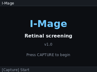
Boot State
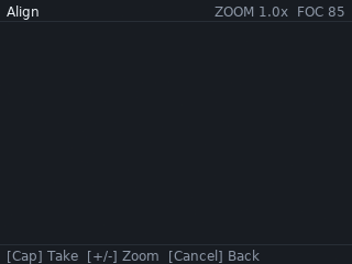
Align State
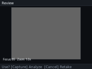
Review State
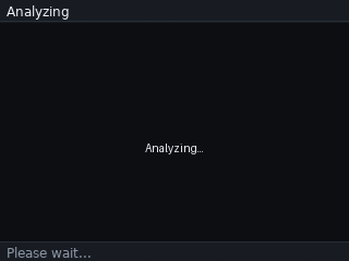
Analyze State
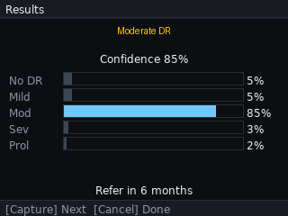
DR Results
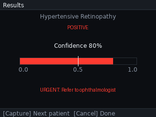
HR Results
10. Key engineering decisions
A working prototype hides the choices that got it there. A few of ours are worth setting out, because they explain why the device looks the way it does, and because each one is a small lesson in building to a constraint.
Dropping the ESP32:
The first design used an ESP32 to drive the display and buttons while the Pi handled capture and inference, with the two talking over a serial link. It worked, but the link was a hard ceiling. Streaming a live preview across it topped out near 2.4 frames per second, far too slow to align against a moving retina. No amount of tuning moves a bandwidth wall, so we removed the ESP32 and moved the display onto the Pi. Fewer parts, one less thing to fail, and the preview became a software problem we could solve.
Float16, not INT8:
Quantizing a model to 8 bit integers is the usual way to shrink it for an edge device, but it costs some accuracy, which matters when the output is a disease grade. The Pi has enough spare compute that we did not need to. Keeping the model in 16 bit float halved its size, from 11.4 MB to 5.7 MB, sped inference up by about a quarter, and changed the test kappa by 0.0013, from 0.8124 to 0.8111, which is nothing. We got the size and speed of quantizing without the accuracy cost of full INT8.
Designing for the Pi 4:
The Pi 5 in the prototype came from the iBot Club's inventory, not from the design. The workload, one quantized model and a small UI, does not need it. The recommended build uses a Pi 4, which roughly halves the most expensive part, draws far less power, and is documented next to the Pi 5. The differences come down to the GPIO library and measuring two timings again.
Splitting the power:
An early plan ran the whole device from two 18650 cells through a boost converter, but the Pi 5's current peaks browned it out. Rather than fight it, we split the power into two supplies. The Pi runs from a stable USB-C source, and the battery and boost drive only the LED, switched on its own. The instability went away, the wiring got simpler, and the operator got a direct on and off for the light.
11. Building it
The build has four parts: print the housing, wire the electronics, fit the optics, and load the software. It needs a 3D printer, a soldering iron for the few power joints, and basic hand tools. The full pin list is in the wiring diagram above. The steps below give the order and the things that are easy to get wrong.
1. Loading the software:
1.Flash Raspberry Pi OS to the microSD card:
Using the Raspberry Pi Imager software as follows, Pi OS lite could be installed,
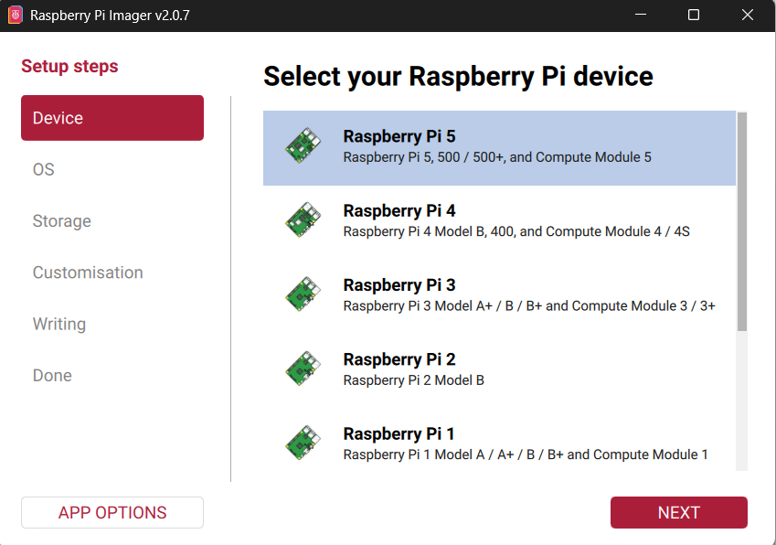
a) Selecting the device: Upon opening the Pi imager, the first setup step will be to select the board. Choose Pi 5 or Pi 4 according to your build.
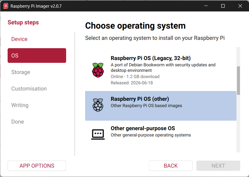
b) Choosing the OS: Clicking "Next" will lead to the OS selecting page. We are going with the Raspberry Pi OS Lite (64-bit) as we don't require an OS with GUI and other heavy stuff. We just need the shell to run scripts and Pi OS lite is the best choice for this. Pi OS lite will not be present as the main options in this page. It will be present under the option called "Raspberry Pi OS (other)". Choose our required OS and click "Next".
.png)
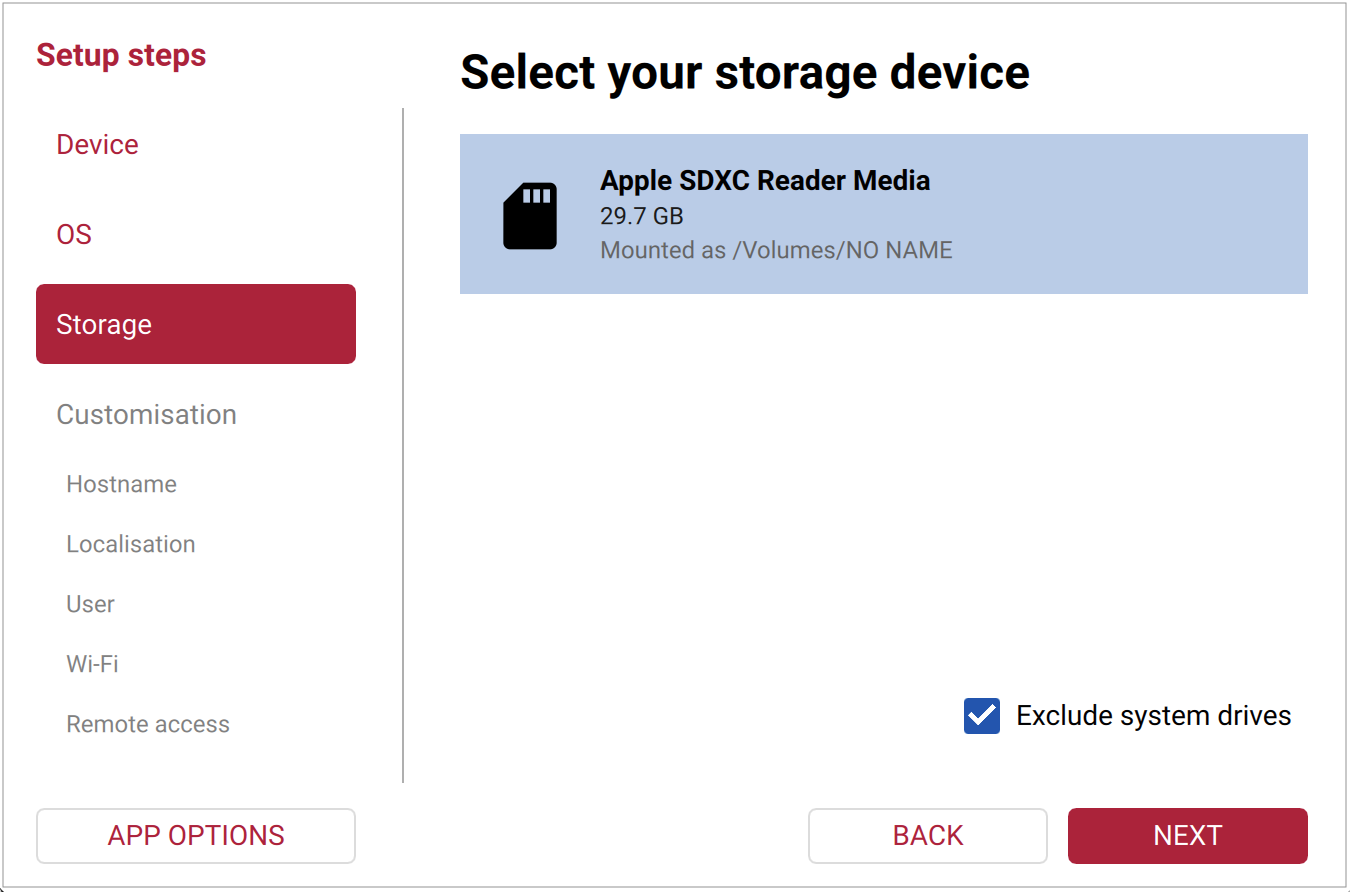
c) Storage: In the Storage tab, select the SD card drive and click "Next"
d) Customisation: This is one of the important steps. Here is where we set our hostname and password(needed for SSH), set up the wi-fi connection for initial updates and setup (can be changed later from inside from the shell) and the most important, enabling SSH, through which we are going to control the Pi.
.png)
Choosing the hostname (you can name it as you wish but remember it)
.png)
Choose the time-zones according to your location
.png)
Set the username and password (kindly do it with care, as it can become quite a hassle later on - words from experience)
.png)
Set up the wi-fi for initial setup of the device. Use your mobile hotspot so that it is easier to find the Pi's IP address
.png)
Most important step of the OS setup, enabling SSH and choosing password (the one setup in the "User" tab) for authentication
.png)
We don't need Pi connect as we are doing it through SSH, so leave it unselected, and click "Next"
e) Writing the OS: After you’ve gone through the tabs in Imager, you can review a Summary of your choices in the Writing tab. Make sure the customisations made match with the customisations shown below.
.png)
After checking and confirming, click "Write". It will display a warning message as shown
.png)
Click "I UNDERSTAND, ERASE AND WRITE". Wait until completion and voila, the OS setup is done. Then safely eject the SD card and insert into the SD card slot of the Pi.
2. Initial Pi setup:
Power the Pi using a mobile charger which supports 5V/3A rating and turn it on. Make sure to keep your mobile hotspot turned on. The initial boot will take some time as the Pi is reading the SD card OS is getting setup. During this time the green led on the Pi will be blinking. Wait until the blinking stops.
Once the blinking stops, using your mobile's hotspot, find the Pi's IP address. It will be connected under the hostname that we gave in the previous step.
Now on your windows laptop - make sure it is connected to your mobile's hotspot too, open the terminal and enter the following command
ssh hostname@IP_addressIt will ask for authentication, type "yes" and enter. Now, you are connected to Pi's shell.
Now run the following commands for updating the system, enabling SPI for display and for installing dependencies
# System update
sudo apt update && sudo apt upgrade -y

sudo raspi-config nonint do_spi 0  # Enable SPI
echo "SPI status (0=enabled): $(sudo raspi-config nonint get_spi)"

# System Python packages
sudo apt install -y \
python3-pip python3-numpy python3-opencv python3-pil \
python3-picamera2 python3-spidev python3-gpiozero python3-lgpio \
rpicam-apps unzip

# Pip packages
pip install --break-system-packages -U \
adafruit-blinka \
adafruit-circuitpython-ili9341 \
ai-edge-litert
#Verify the downloads:
python3 -c "
import board, busio, spidev, numpy, cv2, PIL
from picamera2 import Picamera2
from gpiozero import Button, PWMLED
from ai_edge_litert.interpreter import Interpreter
print('All imports OK')
"
#Verify the camera:
rpicam-hello --list-cameras
Create the following directory structure: (Don't mind the name, it contains the project name that was initially decided)
mkdir -p ~/healthsnap/models
mkdir -p ~/healthsnap/preprocessing
ls -la ~/healthsnap
Note: The two models are trained in different ways. One is done locally and other on cloud. We did this to learn about the different ways models are trained and what are the pros and cons of each of this. So, don't mind the inconvenience.
3. Training the DR model:
Download the APTOS 2019 dataset and upload it to your drive under the folder called "datasets" and create another called "healthsnap" (Again I would like to mention this, healthsnap was the first name we came up with so it is still lingers around in some of the code, thus don't mind it), and another called "healthsnap_artifacts". Inside the "healthsnap" folder, create a subfolder called "preprocessing" and upload the files present in the preprocessing module attached in the Attachments section.
Now we are ready to train the model. Download the google colab notebooks for DR model from the Attachments and run them in order in google colab with TPU runtime.
Once completing the quantization notebook, the quantized models will be present inside the "phase 5". Download them.
4. Training the HR model:
Download the Task 2 dataset of CGI-HRDC (hypertensive retinopathy classification). Create a folder called "healthsnap_training" with the following structure,
.png)
Move the downloaded dataset after extraction to the "data" folder. Download the HR model jupyter notebooks from the Attachments and move to the "notebooks" folder.
The training is going to be done locally using WSL + Conda environment. For installation and GPU passthrough of WSL, follow the forums given,
WSL Installation: https://learn.microsoft.com/en-us/windows/wsl/install
GPU Passthrough: https://learn.microsoft.com/en-us/windows/ai/directml/gpu-cuda-in-wsl
Once WSL2 and GPU passthrough has been setup, we must setup the Conda Environment. Here are the steps for doing this,
Inside WSL2,
# Miniconda installation
cd ~
wget https://repo.anaconda.com/miniconda/Miniconda3-latest-Linux-x86_64.sh
bash Miniconda3-latest-Linux-x86_64.sh
Accept license, install to default location (~/miniconda3), and answer yes to "initialize conda"
Then restart shell:
source ~/.bashrcThen create the training environment:
conda create -n image python=3.11 -y
conda activate image
Install TensorFlow and cuda:
pip install tensorflow[and-cuda]==2.20.*Install other dependencies:
pip install \
  numpy pandas matplotlib scikit-learn \
  opencv-python-headless pillow \
  tqdm jupyterlab ipywidgets \
  kaggle
Using the Windows File explorer move the "healthsnap_training" folder to WSL as follows,
.png)
Click the Linux section in the file explorer and you will find your Linux distro here. Open the folder
.png)
Inside it, find the home directory and open it. And you will see the all the users linked to this distro. Open the folder with username within which you have downloaded and setup Conda.
.png)
Move the folder here
Now, you could start your training by enabling conda environment and run the Jupyter notebooks in browser as follows,
Inside WSL2,
conda activate imageOpening Jupyter in Browser,
cd ~/healthsnap_training/notebooks
jupyter lab --no-browser
And run the Jupyter notebooks in order.
At the end of the quantization notebook, the float16 model trained will be present inside the "models" directory in "healthsnap_training" directory. Move it from Linux filesystem as shown before to windows filesystem.
5. Transferring the models and app to the Pi:
Using the following scp commands move the files from windows to your Pi,
# Moving the models to the Pi:
scp "path to dr_model_float16.tflite" Pi_username@IP:~/healthsnap/models/
scp "path to hr_model_float16.tflite" Pi_username@IP:~/healthsnap/models/

# Moving the app to the Pi:
scp -r "<path>\preprocessing" Pi_username@IP:~/healthsnap/
scp "<path>\app.py" Pi_username@IP:~/healthsnap/
6. Creating the systemd service:
To make the app.py run on boot instead of us calling it every time, we should make it a systemd service. Here steps to make app.py as a systemd service,
a) Hardware check script: This runs before app.py. If display or camera missing, app doesn't start (avoids crash loop).
cat > ~/healthsnap/check_hardware.sh << 'EOF'
#!/bin/bash
# Hardware preflight for HealthSnap
# Exit 0 = OK to start app.py
# Exit 1 = something missing, don't start

# Check SPI device exists
if [ ! -e /dev/spidev0.0 ]; then
    echo "FAIL: /dev/spidev0.0 not found (is SPI enabled?)"
    exit 1
fi

# Check camera detected
if ! rpicam-hello --list-cameras 2>/dev/null | grep -q "imx219"; then
    echo "FAIL: Camera not detected"
    exit 1
fi

# Check model file
if [ ! -f /home/snap/healthsnap/models/dr_model_float16.tflite ]; then
    echo "FAIL: TFLite model missing"
    exit 1
fi

# Check preprocessing module
if [ ! -f /home/snap/healthsnap/preprocessing/__init__.py ]; then
    echo "FAIL: preprocessing package missing"
    exit 1
fi

echo "OK: hardware + files ready"
exit 0
EOF

chmod +x ~/healthsnap/check_hardware.sh
b) Service file:
sudo tee /etc/systemd/system/image.service > /dev/null << 'EOF'
[Unit]
Description=I-Mage retinal screening app
After=multi-user.target network.target
Wants=multi-user.target

[Service]
Type=simple
User=snap
Group=snap
WorkingDirectory=/home/snap/healthsnap

# Hardware preflight
ExecStartPre=/home/snap/healthsnap/check_hardware.sh

# The app
ExecStart=/usr/bin/python3 /home/snap/healthsnap/app.py

# Restart only on crash, not on hardware-missing
Restart=on-failure
RestartSec=10
StartLimitBurst=5
StartLimitIntervalSec=600

StandardOutput=journal
StandardError=journal

[Install]
WantedBy=multi-user.target
EOF
c) Enabling and starting the service:
sudo systemctl daemon-reload
sudo systemctl enable image.service
sudo systemctl start image.service
Useful commands for debugging:
| Command | What it does |
|---|---|
sudo systemctl status image | Current state |
sudo systemctl stop image | Stop (for debugging) |
sudo systemctl start image | Start manually |
sudo systemctl restart image | Restart |
sudo systemctl disable image | Disable auto-start |
sudo journalctl -u image -f | Live logs |
sudo journalctl -u image -n 100 | Last 100 lines |
2. Print the parts. The housing prints in 5 pieces: the body that holds the electronics which consists of a case and slide, the long optical tube, a two part hollow cylinder (lens holder) that holds the lens firmly in the optical tube, and the eyecup. Figure below shows all the parts laid out before assembly.
.jpeg)
The Case
.jpeg)
The Slide
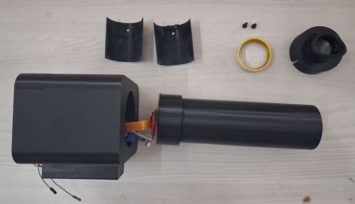
Long Optical tube, Lens holder (2 pcs) and Eyecup and Screws for moving the parts of the lens holder
3. Wire the buttons. The four buttons go to GPIO 17, 27, 6 and 23. Instead of running a separate ground from each one, solder a common ground rail onto a small piece of perfboard and run one wire from that rail to any GND pin on the Pi. Each button then needs only its signal wire. The buttons sit two on each side of the screen on the front face.
.jpeg)
Buttons wired using perfboard rail as common GND
4. Wire the display. The 2.2 inch ILI9341 connects to the Pi over SPI. The signal lines (CS, DC, RESET, MOSI, SCK), the backlight and VCC all go as shown in the wiring diagram. The one thing to get right is that the backlight and VCC both go to 3V3, not 5V. Seat the display in the front face of the body.
Display wired to RPi 5
5. Wire the power. Two separate supplies, and they do not touch. The Pi runs from a USB-C charger straight into its USB-C port. The light runs off two 18650 cells in a switched holder, into the input of an XL6009 boost converter, with the output set to 12V and wired to the LED. Set the output voltage with the converter's trimpot before you connect the LED (use a multimeter to check output voltage). The XL6009 mounts at the joint between the body and the tube. Glue the battery holder to the bottom of the casing.
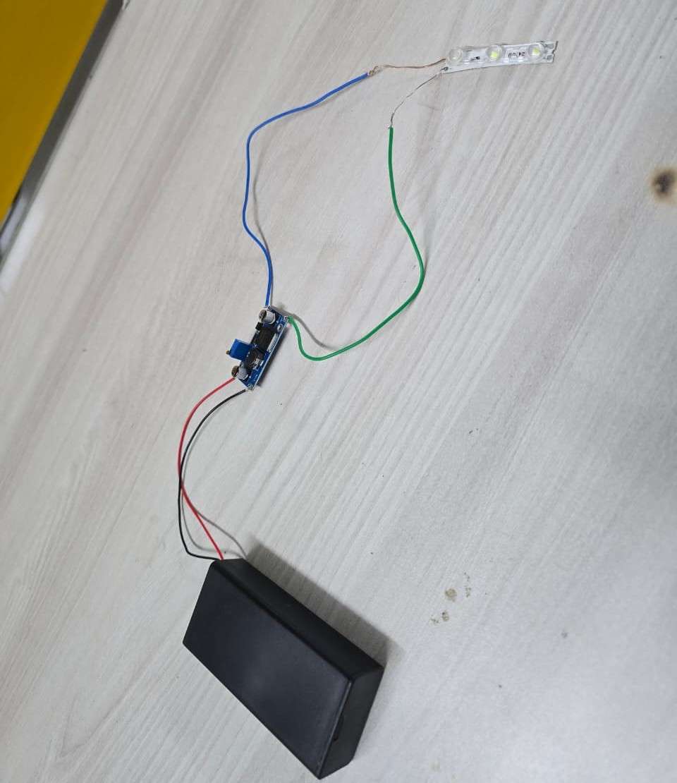
LED power circuit
Battery holder glued to bottom of casing
Mounting of the LED power circuit
6. Mount the camera and lens. The Pi Camera Module 2 mounts at the body end of the optical tube, facing down the tube, with its ribbon running back to the Pi's camera port. Seat the 20D lens in its ring at the front of the tube, with the eyecup over it.

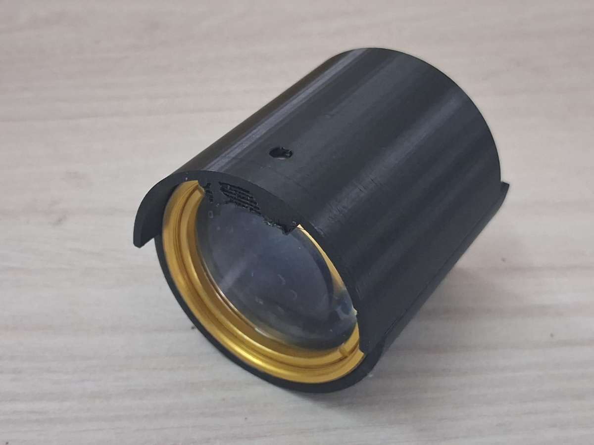
Lens placed in the lens holder
Lens along with its holder placed in the optical tube
Mounting the eyecup

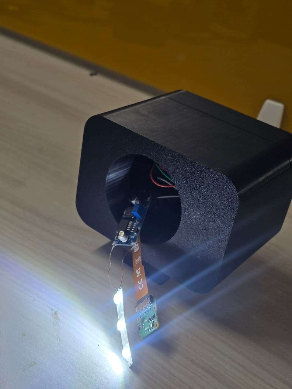
Pi Camera Module and LED strip mounted at body end of optical tube
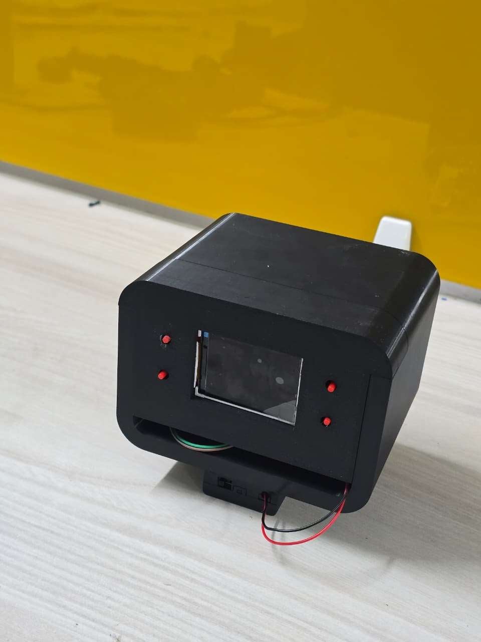
7. Assemble the housing: Slide the tube onto the body, clamp it with the two part collar, and fit the eyecup at the front. Route the camera ribbon and the LED wires through the joint before you close it. The finished device looks like the image attached below.
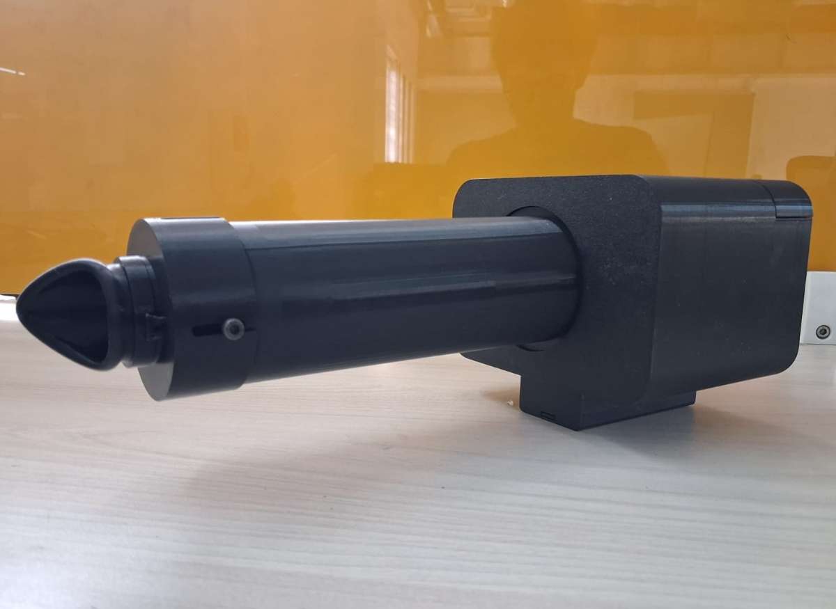
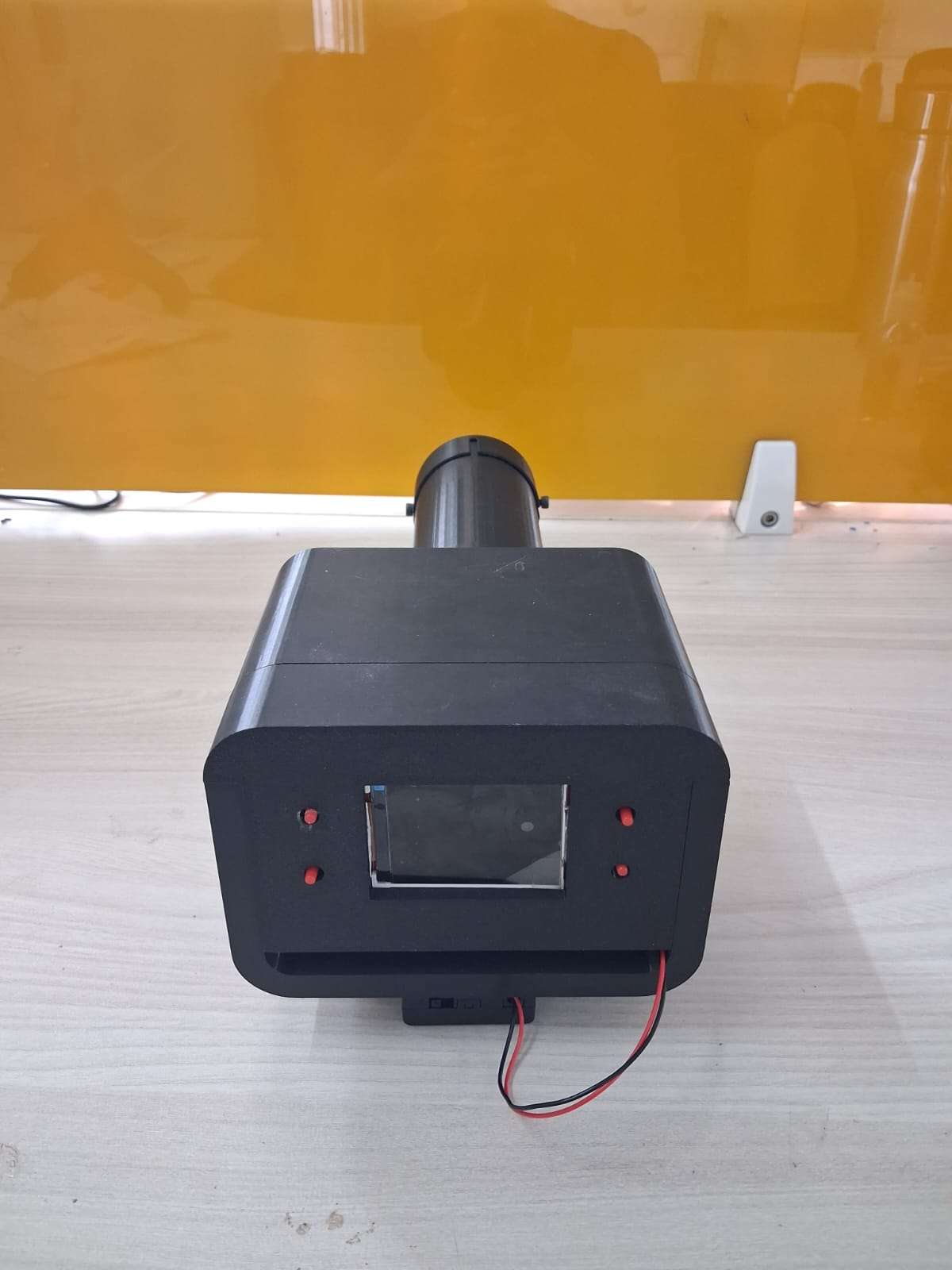
The Finished Device
And voila!, we have successfully completed the all the steps and acquired our device.
12. Testing and limitations
Two parts of I-Mage have been tested, and they sit at very different stages.
The models are tested properly, on held out public data. The DR grader reaches a test kappa of 0.81 and flags referable disease at about 69% sensitivity and 98% specificity, with the full breakdown in the AI section. The HR model is honest early work, around 79% sensitivity and 48% specificity, not yet good enough to screen with. These are real numbers on real test sets, including the parts that are not flattering.
The optics have had only a first bench capture, but it is an important one. Through the 20D lens, the device resolves the optic disc and the retinal vessels, which confirms the optical path works and the camera is seeing the back of the eye. The same capture also shows the main limitation.
The brightest thing in that image is not retina. It is a central corneal reflex, the LED reflecting off the front of the eye back into the camera, sitting right over the macula where the most important findings appear. This reflection can be reduced with crossed polarisers, one film over the LED and one over the lens at ninety degrees, which cancels the specular glare while the diffuse light returning from the retina still passes. We were not able to add the polarisers before the deadline, so the current capture still carries the glare. It is the first thing to fix, and it is a known fix rather than an open problem.
Another limitation is that it is mydriatic, that is, the pupils must be dilated before retinal screening using I-Mage. This adds roughly 30 minutes to the screening - time that causes a bit of inconvenience. This could be removed by using IR LED lights and IR camera. Our eyes are not sensitive to IR lights (pupils stay dilated), thus if the screening is done in a dark room (pupils become dilated), the retinal focusing could be done using the IR lights by the operator and could be captured by the camera after flashing a white light in a split second. We have linked a paper about this in the references. We could not do this due to unavailability of the IR camera. So the readers are welcome to experiment about this too.
The other limits are worth stating plainly. I-Mage is a prototype and a screening aid, not a diagnostic, and neither model has been tested on a clinical population. Both were trained on public datasets, so they inherit whatever those datasets lack. The DR model under grades a share of moderate cases, and the central glare sits exactly where those cases would show, so the two problems compound until the optics are fixed. The device images one eye at a time, needs a steady hand and some practice to align, and its field of view and behaviour across pupil sizes are not measured yet. The light has its own battery, but the Pi still needs a mains USB-C supply, so the device is portable rather than fully cordless. Every one of these has a clear next step, and most of them are work rather than invention.
13. Conclusion
I-Mage started from a simple inspiration. The diseases the retina reveals are everywhere in India, and the means to screen for them are not. It is a prototype, not a finished product, and not a diagnostic. But it works well enough to make the point: the core of retinal screening, a camera, a light, a lens and a model, can be rebuilt offline and open for about ₹12,000, and put where there is no specialist today.
The parts list, the wiring, the printed housing and the code are all here for anyone to take. If you have a 3D printer and the parts, you can build one. More than that, you can change it. The optics still throw a central glare that better illumination will fix. The camera sits on a card mount that wants a printed one. The wiring would be cleaner on a single board, and the models can be trained harder and on more data. None of this is settled, and we would be glad to see someone build a better version than ours. That is the whole reason for putting it in the open.
The hardest part of this project was not the hardware or the model. It was the data. Good, labelled retinal datasets for screening are scarce, especially for hypertensive retinopathy, where the one public benchmark we could find holds only a few hundred images. A model can only be as good as what it learns from, and for several of the conditions the retina can reveal, that data barely exists in the open. This is where the project needs people with skills and access we do not have: ophthalmologists, graders, clinics and researchers who hold or can label retinal images. If that is you, the most useful thing you can give an effort like this is not code, it is data. Open, well labelled, and from varied populations. Close that gap and a cheap screener like this one stops being a proof of concept and starts being useful.
I-Mage was built to show what is possible at the low end. Innovate on it and make it better than we did.
References
- A Portable, Inexpensive, Nonmydriatic Fundus Camera Based on the Raspberry Pi® Computer
- Diabetes burden: ICMR-INDIAB study, Lancet Diabetes & Endocrinology, 2023.
- DR prevalence: SMART India study, Lancet Global Health, 2022.
- Screening gap and specialist shortage: Indian Journal of Ophthalmology, 2022; reviews on training non specialist graders.
- Mobile screening unit cost: published cost analysis of community DR screening.
- Comparators: Peek Vision (Peek Retina); Remidio Fundus on Phone with Medios AI; Optomed Aurora.
- HR dataset: CGI-HRDC, Hypertensive Retinopathy Diagnosis Challenge, Computer Graphics International 2023 (Qian et al., The Visual Computer, 2025).
- DR dataset: APTOS 2019 Blindness Detection (Kaggle).