
WORKING:
Here, Temperature is taken from the LM35 temperature sensor.LM35 converts surrounding temperature into analog voltage(equivalent to temperature). This analog voltage is provided to ADC0808 for digital conversion.
After digital conversion, the final temperature gets displayed on the LCD display.
LCD(16X2) DISPLAY:
- RS, RW, EN pins are connected to P2.5 to P2.7 of 8051 respectively.
- Data pins (D0 to D7) are connected to P3.0 to P3.7 of 8051 respectively.
LM35 SENSOR:
- VCC pin is connected to 5 v supply.
- VOUT pin is connected to the IN0 channel of ADC 0808.
- On the VOUT pin, we get equivalent voltage with respect to the surrounding temperature.
- The temperature change is 10 mv/°c.
- GND pin is connected to GND.
ADC 0808:
- VCC pin is connected to 5 v supply.
- VREF(+) pin is connected to a 2.56V supply.
- VREF(-) pin is connected to GND.
- OUT8(LSB) to OUT1(MSB) pins are connected to P1.0(LSB) to P1.7(MSB) respectively. i.e. OUT8 pin is connected to P1.0 and OUT 7 pin is connected to P1.1 and so on. Likewise, all the pins are connected.
- The START pin is connected to P2.1 of 8051.
- ALE pin is connected to P2.3 of 8051.
- The OE pin is connected to P2.4 of 8051.
- EOC pin is connected to P2.0 of 8051.
- ADDC, ADDB, ADDA pins are connected to P0.7 to P0.5 respectively.
- CLOCK pin is connected to P2.2 of 8051.
Step size of ADC0808:
According to step sequence ADC converts the value.
Here,Step size = [vref(+) - vref(-)] / [2^8];
Here supposed vref(+) is connected to VCC pin of ADC 0808 then step size is equal to 19.53mv.
Calculation of vref(+) with step size of 10mv:
- 10*10^-3=[vref(+) - 0v]/256
- vref(+)=(10*10^-3)*(256)
- vref(+)=2.56v
(10 mv is taken because the temperature change of LM35 sensor is 10mv/°c)
Steps to interface with ADC0808:
1.Provide a clock signal of frequency (10 kHz up to 640 kHz)on the clock pin of ADC 0808.I have selected the frequency of 15khz. Make EOC an input pin. Clear START, ALE, and OE pin of ADC0808.
2.Select the appropriate channel by sending a signal to ADDA, ADDB, ADDC pin of ADC0808.
If we are taking analog signal from pin IN0 then select channel 0. Whenever we are giving signals to pin IN0 to IN7,it is necessary to select the appropriate channel with respect to that pin.
Here I have provided the analog output of the LM35 sensor to pin IN0 of ADC 0808, hence I have selected channel 0 by providing 0 to ADDC, ADDB, ADDA pin of ADC 0808.
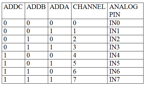
TABLE 1 :CHANNEL SELECTION TABLE OF ADC 0808
3.Send high to low pulse on the start pin of ADC0808.
4.Send high to low pulse on ALE pin of ADC0808.
5.Wait for EOC(End of conversation)signal to become high to low.
6.Make OE(Output Enable) pin high.
7.Take the data from the port of 8051 where output pins(OUT1 to OUT8) of ADC 0808 are connected.
Here I have connected output pins of ADC 0808 to Port 1 of 8051. Hence I have taken data from Port 1.
8.Clear OE pin.
9.Repeat the steps from step 2 for continuous conversion.
PROGRAM:
#include<reg51.h>

#include<string.h>


sbit RS = P2^5;

sbit RW = P2^6;

sbit EN = P2^7;

sbit ale=P2^3;

sbit oe=P2^4;

sbit start=P2^1;

sbit eoc=P2^0;

sbit clk=P2^2;

sbit chc=P0^7;  //Address pins for selecting input channels.

sbit chb=P0^6;

sbit cha=P0^5;


void delay(int t);

void lcd_init(void);

void lcd_command(char c);

void lcd_data(char d);

void str(char a[]);

void print( long float p);

long float k;

unsigned long int q,r,x,y,z;


void timer0() interrupt 1  // TIMER 0 interrupt ISR

{

    clk=~clk;

}


void main()            // MAIN PROGRAM

{

lcd_init();                                // lcd initialization

str("!!welcome!!");

lcd_command(0x01);  // clear display

str("Temp:");

lcd_command(96); //custom character (°c) display

lcd_data(0x10);

lcd_data(0x07);

lcd_data(0x08);

lcd_data(0x08);

lcd_data(0x08);

lcd_data(0x08);

lcd_data(0x07);

lcd_command(0x8b);

lcd_data(4);

eoc=1;             // make eoc an input

ale=0;

oe=0;

start=0;

TMOD=0x02;    // timer 0 in mode 2

TH0=0xc2;                   //     15khz

IE=0x82; //  set timer 0 interrupt

TR0=1;   // start timer 0

while(1)

{

chc=0;  // select channel 0

chb=0;

cha=0;

ale=1;  // send high to low pulse on start and ale pin

start=1;

delay(1);

ale=0;

start=0;

while(eoc==1);     // wait for conversion

while(eoc==0);

oe=1;

k=P1;

lcd_command(0x85);

print(k);   // send the digital data to lcd

oe=0;

}

}

void str(char a[])  // lcd function to display string

{

int j;

for(j=0;a[j]!='\0';j++)

{

lcd_data(a[j]);

}

}

void lcd_init(void)  // lcd initialization

{

lcd_command(0x38);        //8 bit,2 line,5x8 dots

lcd_command(0x01);        // clear display

lcd_command(0x0f);      // display on, cursor blinking

lcd_command(0x06);     //Entry mode

lcd_command(0x0c); //cursor off

lcd_command(0x80); //// force cursor to beginning of first row

}

void lcd_command(char c) // lcd command function

{

P3=c;

RS=0;

RW=0;    // select command register

EN=1;

delay(5);

EN=0;

delay(5);

}

void lcd_data(char d) // lcd data function

{

P3=d;

RS=1;               //select data register

RW=0;

EN=1;

delay(5);

EN=0;

delay(5);

}

void delay(int t)      // delay function

{

int j;

for(j=0;j<t*1275;j++);

}

void print( long float p)  // number display function

{

x=p*10;

if(x>=1000)

{

q=x/1000;

q=q+48;

y=(x%1000)/100;

y=y+48;

z=((x%1000)%100)/10;

z=z+48;

r=x%10;

r=r+48;

lcd_data(q);

lcd_data(y);

lcd_data(z);

lcd_data(46);      //ascii value of point

lcd_data(r);

}

else

{

q=x/100;

q=q+48;

y=(x%100)/10;

y=y+48;

z=x%10;

z=z+48;

lcd_data(q);

lcd_data(y);

lcd_data(46);                      //ascii value of point

lcd_data(z);

r=0;

lcd_data(r);

}

}
PROGRAM DESCRIPTION:
First I have initialized the LCD by providing the various LCD commands required for initialization.After that LCD command function and LCD data function are declared. Delay function is used to provide sufficient delay. The string function is used to print the string.
In LCD to pass the commands, the command register needs to be selected, and the enable pin must be provided with a high to low pulse to process those commands. The command register is selected by providing logic 0 to RS(Register Select) pin of LCD.
To pass the data to the LCD, the data register need to be selected, and an enable pin must be provided with high to low pulse to process that data.
Data register is selected by providing logic 1 to RS(Register Select) pin of lcd.
After that I have displayed the custom character of degree Celcius by selecting appropriate pixel of lcd.To know how to display custom character on an lcd please visit the below link:
https://embeddedprojects222.blogspot.com/2020/09/to-display-custom-characters-on-lcd.html
For generating the clock signal on the clock pin of adc 0808,I have used timer 0 interrupt.Here I have provided a clock signal of 15khz. Whenever the TF0 flag is set, an interrupt gets generated and the controller starts executing the ISR.
After that I have followed the steps mentioned above(steps for ADC 0808 interfacing).Output is taken from port 1 of 8051 and send to the lcd display.
__________________________________________________________________________________________________________
BASIC PROCEDURE TO DISPLAY NUMBER ON AN LCD(Explanation of number display function):
If we want to display any number which is greater than 9 on an lcd then decompose(break) the number and add 48 to each separated digit of that number and send the resulting value one by one to the lcd.
Here I have taken four digit number as an example. Suppose I want to display 1352 on lcd.
First basic step is initialization of lcd. Then the next step is decompose(break) the number.
Procedure to decompose(break) 4 digit number:
1.First divide the number by 1000.So we get first number.
Ex.1352/1000=1;
2.Divide the number by 1000 and take the remainder of the division .Divide that remainder by 100 so that we can get second number.
Ex.(1352%1000)/100= 3;
Note: [ ( / ) divide operator returns quotient of the division and
(%) modulus operator returns remainder of the division.]
3.Divide the number by 1000 and take the remainder of the division. Divide that remainder by 100.Again take the remainder of the division and divide it by 10.So that we can get third digit of the number.
Ex.((1352%1000)%100)/10= 5;
4.Divide the number by 10 and take the remainder of the division so that we can get last digit of the number.
Ex. 1352%10=2;
There are two ways to display characters on an LCD:
1.One is sending character by writing it into single inverted commas
Ex. a = '0';
2.The other way is sending the ASCII value of the character.
Ex. a = 48; (ASCII value of '0')
Here for displaying the number I have used ASCII value of the characters. ASCII value of '0' to '9' are ranging from 48 to 57 respectively.
Now after decomposing the number, next step is to add 48 to each separated digit so that we can able to get ASCII value of that digit.
Ex.
1+48=49;( ASCII value of 1)
3+48=51;(ASCII value of 3)
5+48=53;(ASCII value of 5)
2+48=50;(ASCII value of 2)
Send those values to lcd display one by one. So that we will be able to display complete number 1352.This is the basic procedure to display number on lcd.
By using the above method I have displayed temperature on an lcd.
__________________________________________________________________________________________________________
Calculation of the value loaded in TH0 register:
I have taken the micro-controller with 11.0592 MHZ frequency.I have used timer 0 in mode 2.So the calculation is
1.(11.0592 MHZ ) / 12 = 921600 HZ
2.1 / (921600) = 1.08*10^-6
3.I want to generate 15 khz frequency.
4.So required time= 1/(15*10^3) = 6.66*10^-5
5.Count= required time / controller time
6.Count = (6.66*10^-5) / (1.08*10^-6)
7.Count = 61.72=62
8.Value to be loaded in timer 0 register= 256 - 62= 194= c2(hex)
9.So in TH0=0xc2 data get loaded.
__________________________________________________________________________________________________________