

As its name defines it, our robot is a basic representation of the spider movements but it will not perform exactly the same body moves since we are using only four legs
STEP 1:3D OBJECT PRINTING
print them out by your 3D printer.
Please check the configuration of the 3D printer before starting to print because it will take a long time about 9~10 hours to print them all. Be patient~~

There are my print setting:
- The fill density - 50%
- Nozzle - 0.3mm
- Print speed - 80
you can print these parts separately by color group.
STEP 2: PREPARING TO ASSEMBLY :
Tear down the parts and check the objects printing quality, and using the sandpaper to polish the surface to make it looks good
And, install all of the servos with legs parts, one leg comes with 3 servos and 4 screws(M1.6x3mm, or glue it anyway)
Notes: 1. Connect to all parts with screws and servos, but do not install the servo rocker arm in this step 2. Be sure the leg direction.
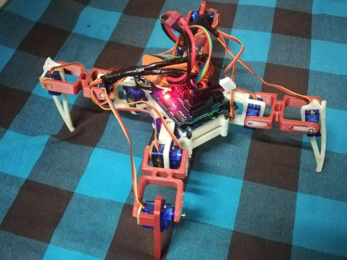
Connect all of the legs to the body, and check all servos and joints are moving smoothly.

STEP 3: CONNECT SERVOS TO THE MAIN BOARD:
Place the main-board onto the body-case and use the polymer clay to fix it.
The signal direction of servo wire, yellow connect to "S", red to "+", brown to "-".
Be sure the servo of legs should match the pin number of main-board and leg direction, otherwise, the legs will get crazy.
Step 4: LOCATE THE INITIAL POSITION FOR LEGS
This is an important procedure, the install procedure:
1. upload the "legs_init" code to Arduino to activate the servos
2. place the legs as the position shows the picture 1, and install the servo rocker arm with screws.
3. tighten all of the Screw.

STEP 5: THE ANDROID APP
Talking about the android up it allows you to
connect to your robot through Bluetooth and make forward and backward movements and left-right turnings, it allows you also to control the robot light color in real-time by picking the desired color from this color wheel.

STEP 6: ARDUINO CODE AND TESTING :
Now we have the robot almost ready to run but we need to set up the joints angles first, so upload the setup code which allows you to put each servo in the right position by attaching the servos in 90 degrees do not forget to connect the 7V DC battery in order to run the robot.
Next, we need to upload the main program to control the robot using the android app.

Video