
Ok, so I was in the final year of my engineering(B.E Naval Architecture which means how to design ships and things that float) we had to do a major project. We had a section called specialization. Basically, we had to take a small part of our main project to do really extensive analysis and calculations which meant lots of excel work. At that time I was not a big fan of excel but now that I have a full-time job I appreciate excel a lot.
Clerical work was beneath young me so he decided to go for some type of practical experiment. He decided to find out the heave coefficient of a houseboat(Which was his major project) by doing scaled mode testing. In layman's terms when a wave hits a floating body, how much it goes up and down. If you are able to tune the hydrodynamic coefficients properly your boat will "jiggle-jiggle" less and you will have a great time.
Here comes the fun part my college did not have any model testing facility so young me decided to build a small wave tank. A wave tank is a laboratory setup for observing the behavior of surface waves. The typical wave tank is a box filled with liquid, usually water, leaving an open or air-filled space on top. At one end of the tank, an actuator generates waves; the other end usually has a wave-absorbing surface.
Here is a wave tank built to study Tsunamis
Usually, these tanks cost a lot of money so I tried to build a really cheap solution for students who want to use the tank for testing their projects. My college agreed to fund it but by the time they released the money my engineering was already over I had to stay behind extra two weeks to finish it. I ended up doing more work :).
This project is open source I have also documented steps on how to build your own. I hope this will help someone like me who does not have proper resource but still want to build cool stuff and if you watch the last video you might see young me explaining all the different parts of the tank and how to operate it.
Section 1: How does it work
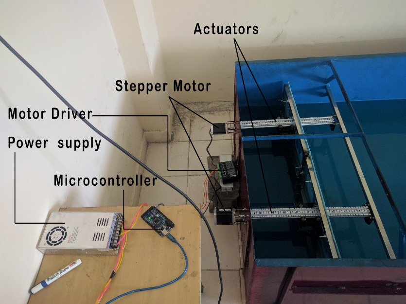
The wave tank consists of two actuators made using v-slot aluminum extrusions. A stepper motor is connected to each actuator and both motors are controlled by the same stepper motor drive so there is no lag.
Arduino is used for controlling the motor driver. A menu-driven program is used to give input to the Arduino connected via pc. Actuator plates are mounted on the v-slot gantry which will go back and forth once the motors start and this back and forth movement of plates generates the waves inside the tank. The wave height and wavelength can be changed by changing the speed of the motor via Arduino.
I have not included materials for the v-slot gantry because the list will be HUGE. If you google v-slot you will get many videos regarding how to assemble it I used 2040 aluminum extrusion. Motor and power supply capacity will change if you want to carry more load.
Tank dimensions(LXBXH) = 5.50 x 1.07 x 0.50 meters
Section 2: Fabricating the body
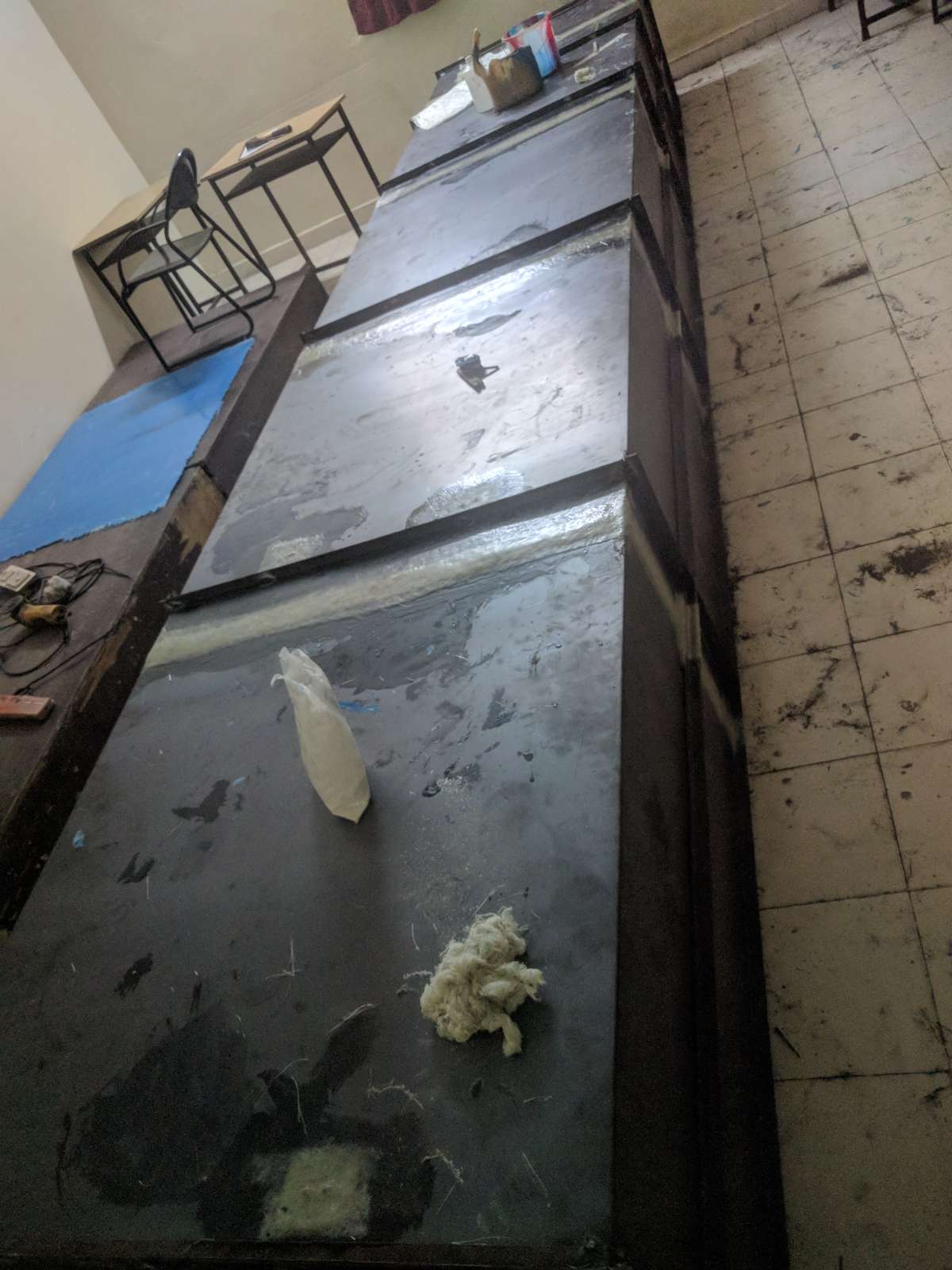
The body is made of a 3 mm thick cast iron sheet.
Tank width is 1.10 meters, length 5 meters, and height 0.5 meters. The tank body is made up of mild steel with stiffeners around it wherever necessary. Mild steel plates were bent and cut into various sections according to the tank dimensions. These sections were then erected by welding them together. Stiffeners were also welded together to make the structure more strong.
.jpg)
First, the plate was bent into the desired size in various sections and then these sections were welded together to erect the body. Stiffeners were added as a support stiffeners dimensions are shown in the picture
Actuator Assembly and Plate Fabrication
Actuators are made using v-slot systems. These are really cheap and easy to build you can google it online and how to assemble one of them. I have used a lead screw instead of a belt drive to increase load carrying capacity. I have not included an assembly tutorial because it will change according to the load you want to carry. For me, the load at maximum speed was around 14Kg. The actuator plate is built using an FRP sheet, acrylic can also be used. A stainless steel frame was built to support the FRP sheet.
Paddle frame
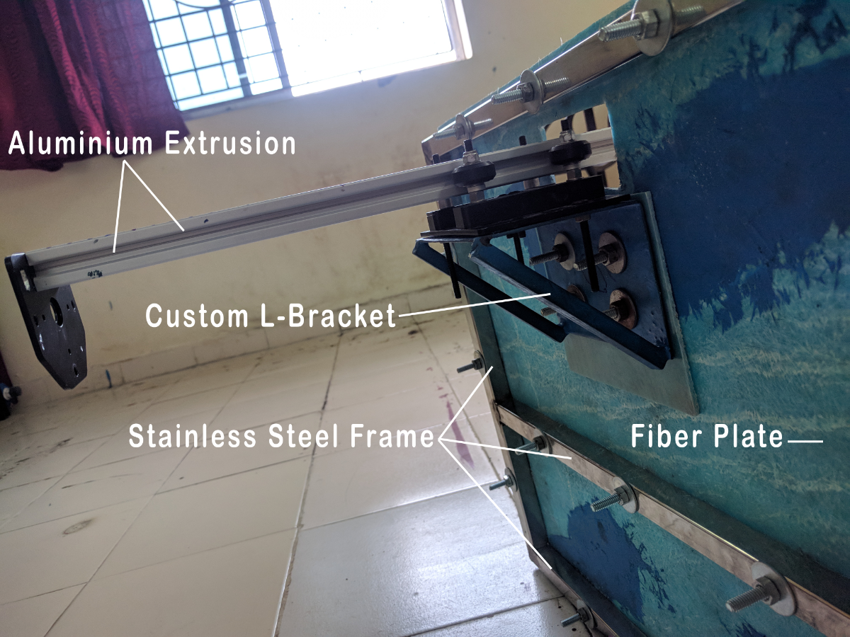
The paddle frame is made up of stainless steel. Stainless steel is waterproof and thus will resist corrosion. A square section of 2 x 2 cm was used for the paddle frame. A sturdy frame was necessary as a lot of cyclic loads will be activated on the paddle during wave generation. The steel frame will not bend and thus will generate the regular sinusoidal wave. A custom L-clamp was made to connect the actuator plate with the gantry plate on the slot system.
Testing and wave characteristics manipulation
The tank can generate different wave heights according to requirements. To generate different wave heights RPM of the motor is adjusted. To get a big wave height RPM of the motor is increased this also decreases the wavelength of the wave. Similar to increasing the wavelength RPM of the motor is decreased. RPM can be adjusted by choosing the custom RPM option from the menu.
Maximum RPM = 250
Minimum RPM = 50
Section 3: Electronic Connections and Programming
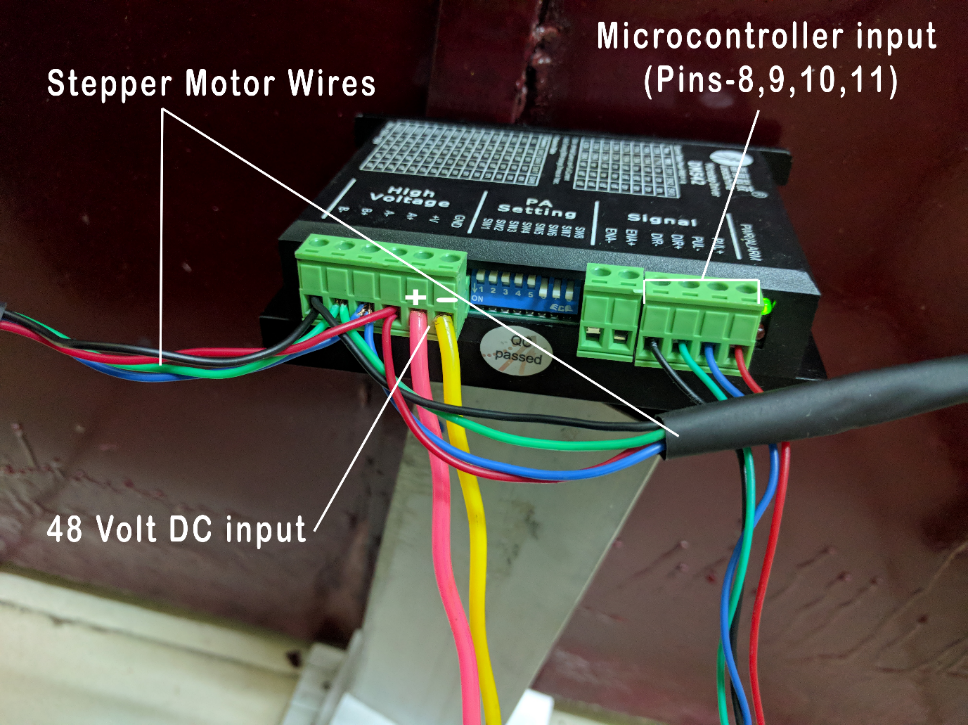
While connecting the power supply pay attention to the connection polarity. Connect the positive terminal to positive and negative to negative.
Make the connections for the motor and driver as shown in the image. Once all the connections are proper connect microcontroller pins (8, 9, 10, and 11) to the stepper motor driver. Connect the microcontroller to a PC by a USB. Start Arduino IDE > Serial monitor.
The Program is included in the tutorial and is self-explanatory it uses switch case and if-else statements to operate.
Controlling the Actuators by Menu Driven Program
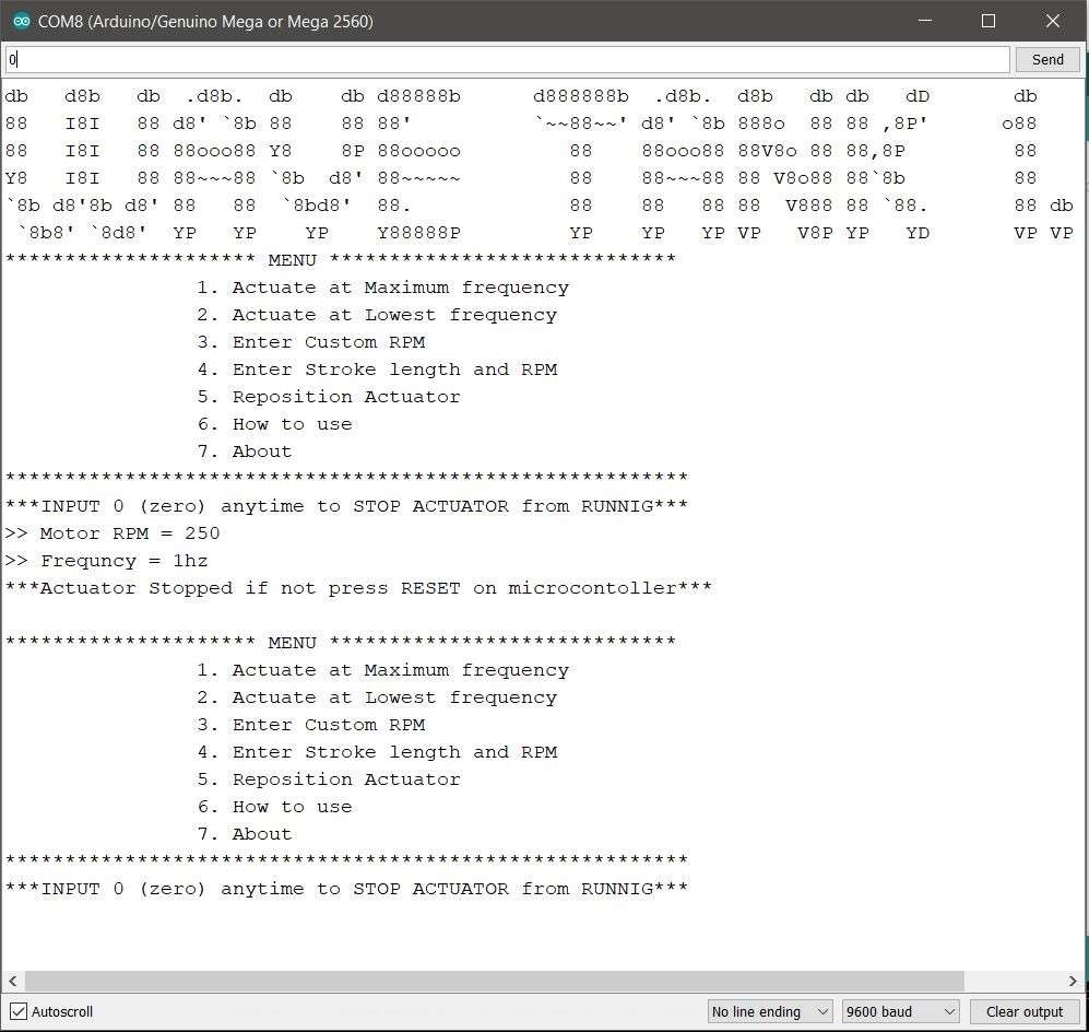
Once the microcontroller is connected properly to the PC you will similar menu. To choose the option just type the number next to the option and press enter
Example:-
To choose “Actuate at maximum frequency” type 1 and press enter.
To stop the action type 0 and press enter.
Emergency stop
To stop the actuator press zero “0” and enter.
To do an emergency stop either press reset on the microcontroller or cut off the power supply.
How to Operate Wave Tank
Writing the step-by-step procedure would be really long so I have made it into a video. Given video will tell you how to use the tank to generate waves and how to change the actuator speeds to generate waves of different wavelengths and wave amplitude. I hope all other doubts will also be cleared in this detailed video as I have explained all the parts of the tanks.
Conclusion
The tank has been tested for the generation of different regular waves in head sea conditions for a scaled barge model. The testing of the wave flume was successful. The overall cost for the development of this project was Rs. 81,000 (Eighty One Thousand Only) for a duration of two months.