MotionSync — A Custom-PCB, 10-Node Wearable IMU Suit for Real-Time Human Motion Capture
From two loose dev boards taped to a wrist, to a single SMD PCB worn across the whole body.
Professional motion capture is one of those technologies everyone needs but almost no one can afford. A single Vicon or OptiTrack optical rig can run past six figures, and even mid-range wearable suits like the Rokoko Smartsuit Pro or Movella DOT kits sit firmly out of reach for student labs, indie animators, physiotherapy clinics, or hobbyist roboticists. The sensors that actually do the work — a 6-axis IMU and a small microcontroller — cost a few hundred rupees each. The price tag commercial suits carry isn't really about the silicon; it's about integration, calibration software, and polish.
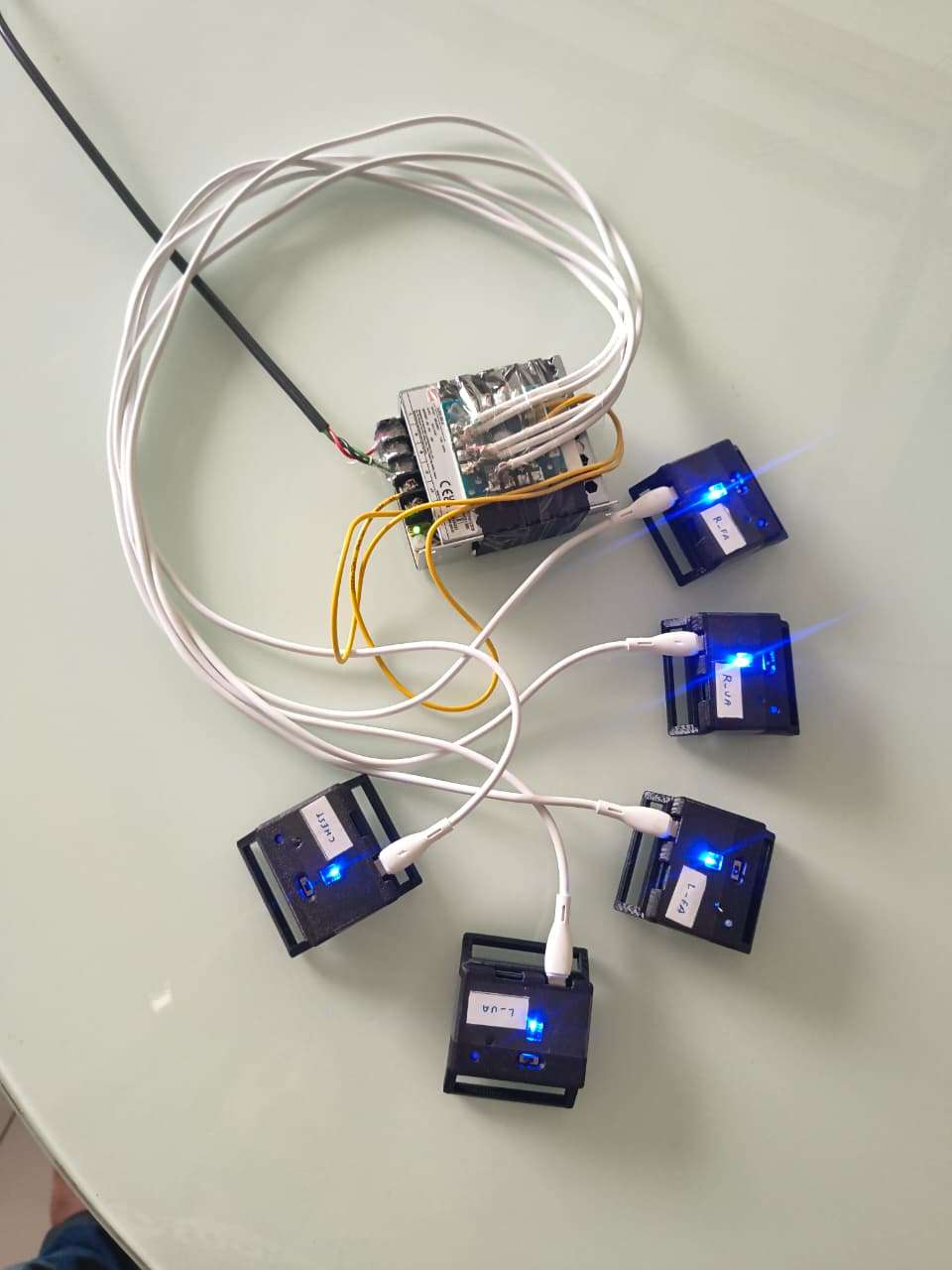
MotionSync sets out to close that gap. It is a fully custom-built, full-body wearable motion-capture suit made from 10 independent IMU nodes, each built around an ESP32-C3 and an MPU6050, strapped onto the hips, chest, both upper arms, both forearms, both thighs, and both shins. Every node streams live orientation data which is logged, calibrated, and finally replayed onto a 3D humanoid skeleton — turning raw sensor noise into smooth, recognizable human movement on screen.
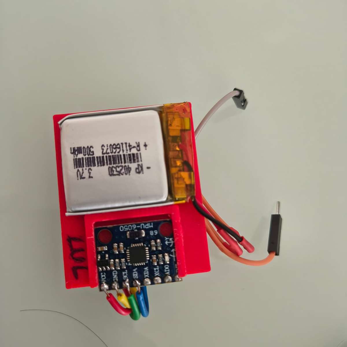
What separates this build from a typical "ESP32 + IMU on a breadboard" weekend project is that it has gone through a full hardware consolidation pass: the original two-board prototype (a separate ESP32-C3 dev board wired to a breakout MPU6050) has been redesigned into a single custom 2-layer SMD PCB per node, with the IP5306 power-management IC handling Li-Po charging and 5V boost output on-board — the same charge/boost architecture used in commercial trackers like SlimeVR's Gen2 nodes. Each board is housed in a compact 3D-printed shell with a status LED, a strap clip, and a slide switch, and the whole thing straps onto the body with Velcro bands, exactly the way a SlimeVR or Movella DOT tracker would.
The project is directly inspired by — and benchmarked against the methodology of — the BodySync research paper (CDSR 2026, PES University), which proposed a 12-node MPU6050/ESP32-C3 suit validated against a commercial Movella DOT system to within ±3° average angular deviation. MotionSync borrows the same calibration philosophy (still calibration + T-pose referencing, quaternion-based hierarchical bone reconstruction) but reimplements the pipeline around a native C++ visualization engine rendering a rigged glTF (.glb) human model, rather than a browser-based Three.js front end — giving tighter control over rendering performance and making it easier to log and replay motion data offline for comparison and analysis (hence the companion repository name, MovementComparision).
What It Actually Does
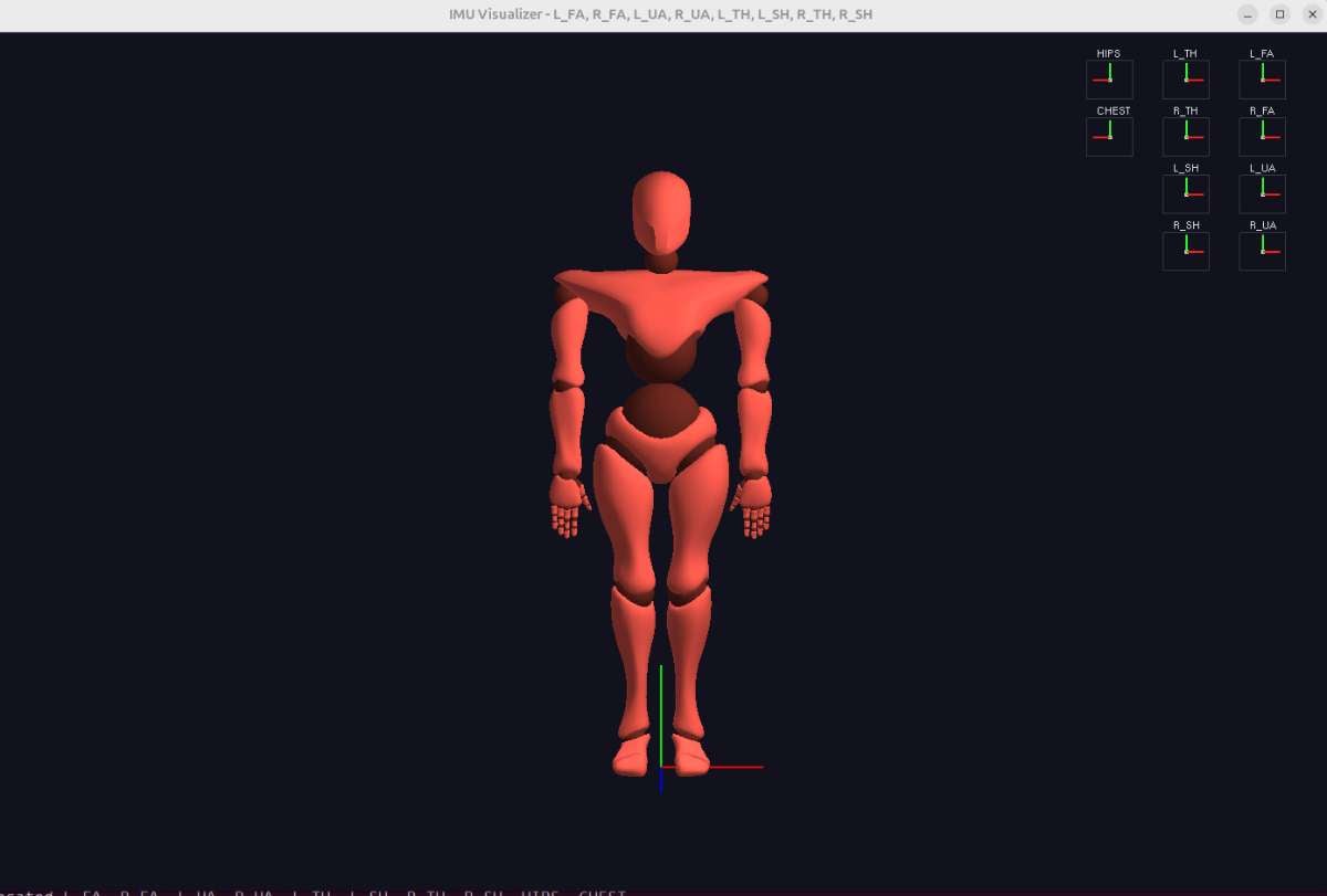
- Ten wearable nodes —
HIPS,CHEST,L_UA,L_FA,R_UA,R_FA,L_TH,L_SH,R_TH,R_SH— each read raw 6-axis motion at high rate from an onboard MPU6050. - Each ESP32-C3 fuses that data into a clean orientation quaternion (
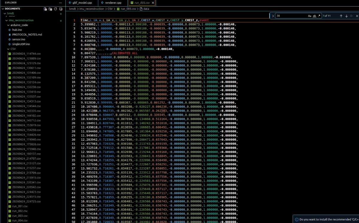
w, x, y, z) and timestamps it. - Data streams off the body wirelessly (or is logged to CSV for offline runs — see
run_005.csvformat below) to a host PC. - A calibration pass — first a still calibration (zeroing gyro/accelerometer bias) and then a T-pose calibration (so every joint's "zero" lines up with the skeleton's rest pose) — converts raw per-sensor quaternions into skeleton-relative bone rotations.
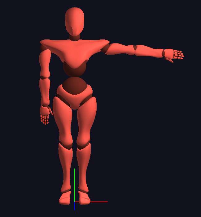
- A custom C++ renderer applies those rotations frame-by-frame to a rigged
human.glb3D model, reconstructing the wearer's pose in real time on screen. - Every run is also saved as a CSV log (timestamp + per-segment quaternion + an
eventcolumn marking calibration milestones likeCALIBRATED_ALL), so recorded sessions can be replayed, plotted, or compared frame-by-frame against a reference system later — the actual purpose behind the MovementComparision repository.
Key Features
- 10 identical, modular wearable nodes — full-body coverage (hips, chest, both upper arms, both forearms, both thighs, both shins) using one repeatable hardware design instead of ten different one-off builds.
- Fully custom, integrated PCB per node — ESP32-C3 + MPU6050 + IP5306 charging/boost circuit + LED + switch on a single board, eliminating loose dev-board wiring entirely.
- On-board sensor fusion — each node computes its own stable orientation quaternion locally (via the MPU6050's DMP) instead of streaming raw, noisy accelerometer/gyro data for a host PC to clean up.
- Two-stage calibration pipeline — automatic still calibration (bias removal) followed by a guided 30-second T-pose calibration, so the suit self-aligns to any wearer's body without manual per-joint tuning.
- Quaternion-based, gimbal-lock-free pipeline end to end — from sensor to skeleton, every rotation is represented and composed as a unit quaternion, avoiding the flips and singularities Euler-angle systems suffer at extreme joint angles.
- Hierarchical, parent-relative bone reconstruction — orientation is propagated down a real skeletal hierarchy (hips → spine → limbs), the same approach used in professional rigging pipelines, not a flat per-sensor mapping.
- Native C++ / glTF visualization — a lightweight, dependency-light desktop renderer applies live rotations to a rigged
human.glbavatar, avoiding the overhead of a browser runtime. - Built-in data logging & replay — every session is captured to a structured, timestamped CSV with calibration event markers, so any run can be replayed, plotted, or compared later without re-capturing.
- Battery-powered, fully wireless wear — each node carries its own Li-Po and onboard charge/boost circuit (IP5306), so the suit has no trailing wires between body segments.
- Visible system status — an onboard LED per node gives an instant power/streaming health check before a capture session starts, without needing a laptop open to debug a "silent" sensor.
- Designed for direct benchmarking — the CSV-first, comparison-oriented workflow (the MovementComparision repo) means the suit's accuracy can be objectively measured against a commercial reference (e.g., Movella DOT) rather than just demoed visually.
.png)
.png)
.png)
Hardware Components
| Quantity | Component Name |
|---|---|
| 10 | ESP32-C3 (Mini/SMD variant) — Wi-Fi/BLE microcontroller, one per node |
| 10 | MPU6050 — 6-axis IMU (3-axis accelerometer + 3-axis gyroscope), I2C |
| 10 | IP5306 — Li-Po charge management + 5V boost converter IC |
| 10 | Custom-designed 2-layer SMD PCB (v1.0) — integrates ESP32-C3, IP5306, LED, switch, battery and header pads |
| 10 | 3.7V Li-Po battery (single-cell, node-integrated) |
| 10 | Status LED (onboard, power/streaming indicator) |
| 10 | Slide/tactile power switch (SW) |
| 20 | SMD resistors (R1, R2 per node — LED current-limiting / pull-up) |
| 10 | JST-style battery connector (BAT pads) |
| 10 | 3D-printed enclosure (body-strap mount with LED window) |
| 10 | Adjustable Velcro/nylon strap (body attachment — hips, chest, arms, forearms, thighs, shins) |
| 1 | USB-C charging/programming cable |
| 1 | Host PC / laptop (runs the C++ visualizer + logs CSV data) |
| 1 | (Optional reference) Commercial IMU tracker, e.g. Movella DOT — for accuracy benchmarking |
Development & Assembly Tools
| Qty | Component | Description |
|---|---|---|
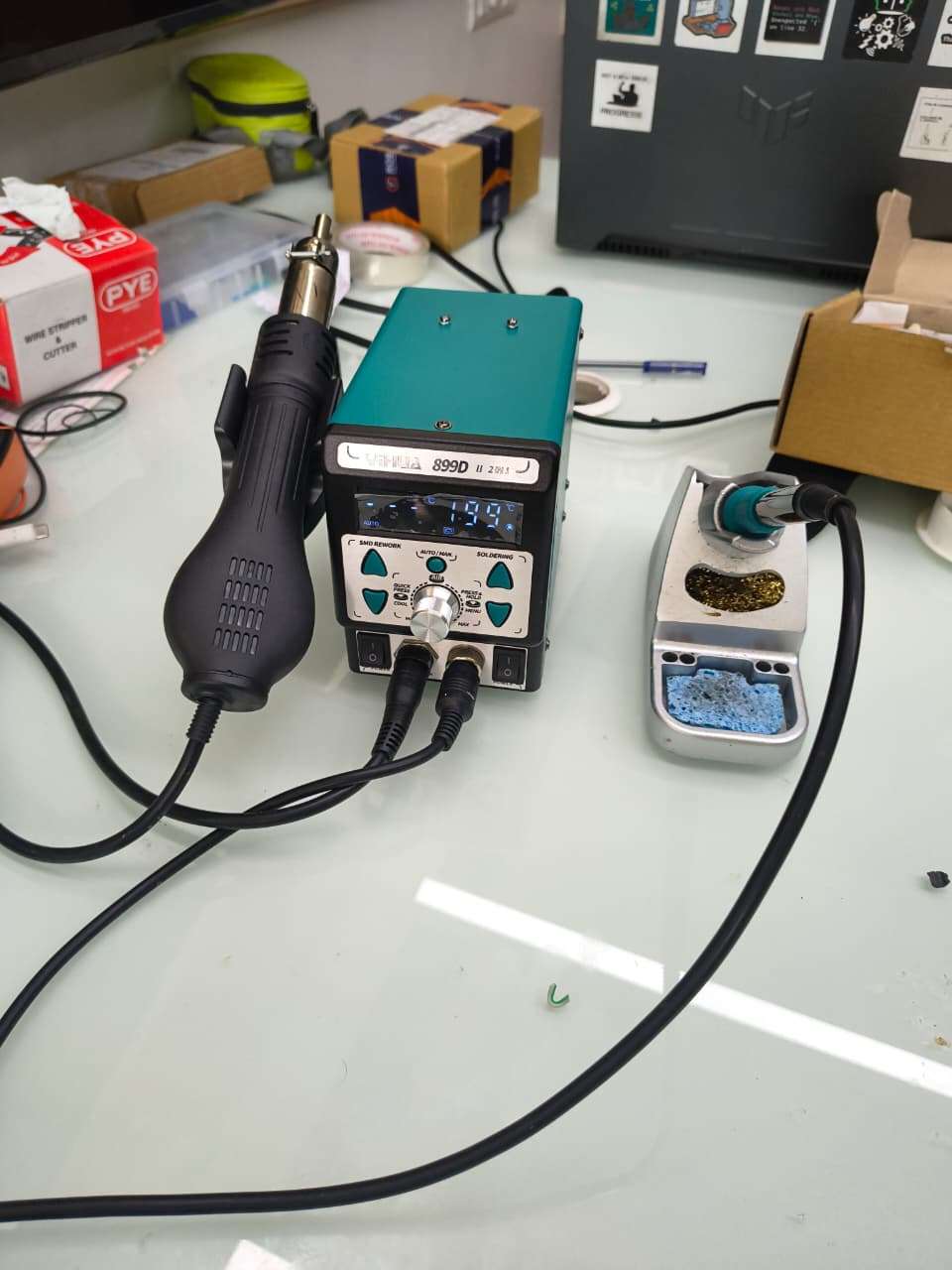
| 1 | Soldering Station | Used to assemble SMD and through-hole components. |
| 1 | Hot Air Rework Station | Soldering and rework of SMD components. |
| 1 | Solder Wire | PCB assembly. |
| 1 | Solder Flux | Improves solder joint quality. |
| 1 | Tweezers | Handling SMD components. |
| 1 | Multimeter | Continuity and voltage testing. |
| 1 | USB Programmer / USB Cable | Firmware upload and debugging. |
| 1 | 3D Printer | Fabrication of wearable enclosures. |
Detailed Component Specifications
1. ESP32-C3 (Mini / SMD module) — Node Microcontroller

| Spec | Value |
|---|---|
| Core | RISC-V single-core, 32-bit, up to 160 MHz |
| Wireless | Wi-Fi 802.11 b/g/n (2.4 GHz) + Bluetooth LE 5.0 |
| Memory | 400 KB SRAM, 384 KB ROM, external flash (typically 4 MB on -MINI-1 module variants) |
| GPIO | Up to ~22 usable GPIOs (fewer on the compact form factor used here) |
| Interfaces used in this project | I2C (SDA/SCL to MPU6050), UART/USB (programming + serial data out), GPIO (LED, switch sense) |
| Operating voltage | 3.3 V logic |
| Power draw | ~20–80 mA active (Wi-Fi transmitting), µA-level in deep sleep |
| Role in node | Reads IMU over I2C, runs calibration logic, packages quaternion + timestamp, transmits/logs data |
2. MPU6050 — 6-Axis IMU
| Spec | Value |
|---|---|
| Accelerometer range | Selectable ±2g / ±4g / ±8g / ±16g, 16-bit ADC per axis |
| Gyroscope range | Selectable ±250 / ±500 / ±1000 / ±2000 °/s, 16-bit ADC per axis |
| Onboard processing | Digital Motion Processor (DMP) — hardware sensor fusion, outputs orientation quaternion directly |
| Interface | I2C, up to 400 kHz (Fast Mode); default address 0x68 (0x69 if AD0 pulled high — used to give two nodes on the same bus distinct addresses if ever needed) |
| Supply voltage | 2.375 V – 3.46 V (VDD), most breakout/SMD modules regulate from 3.3 V supplied by the node board |
| Output used by firmware | Quaternion (w, x, y, z) from DMP, plus raw accel/gyro during the still-calibration bias computation |
| Role in node | Primary motion sensor — every "joint angle" in the final skeleton traces back to this chip's fused orientation output |
3. IP5306 — Power Management IC (Charge + Boost)
| Spec | Value |
|---|---|
| Function | Single-cell Li-ion/Li-Po charger and boost converter in one chip (the same IC family widely used in small power banks) |
| Input | 5 V via USB (micro-USB or USB-C breakout pads on the node PCB) |
| Charge current | Configurable, typically up to ~1 A (set via external resistor/strapping per datasheet) |
| Boost output | Regulated ~5 V output, current capability in the 1–2 A range, used to supply the ESP32-C3's 3.3 V regulator stage |
| Quiescent behavior | Includes light-load auto-shutoff (power-bank-style) — relevant for ultra-low-power applications and worth accounting for in firmware sleep design |
| Status indication | Native LED-driver outputs for charge/battery-level indication, reused here for the node's single status LED |
| Role in node | Lets each node run from one small Li-Po cell while also handling USB charging, removing the need for a separate charger IC and boost regulator |
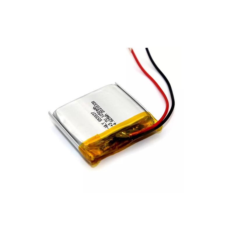
4. Li-Po Battery (per node)
| Spec | Value |
|---|---|
| Chemistry | Single-cell Lithium Polymer |
| Nominal voltage | 3.7 V |
| Typical capacity for this form factor | ~250–500 mAh (sized to fit inside the compact 3D-printed enclosure — confirm your exact cell's printed capacity) |
| Charge termination | 4.2 V (handled by IP5306) |
| Role in node | Sole power source per node; sized for one capture session's worth of continuous streaming between charges |
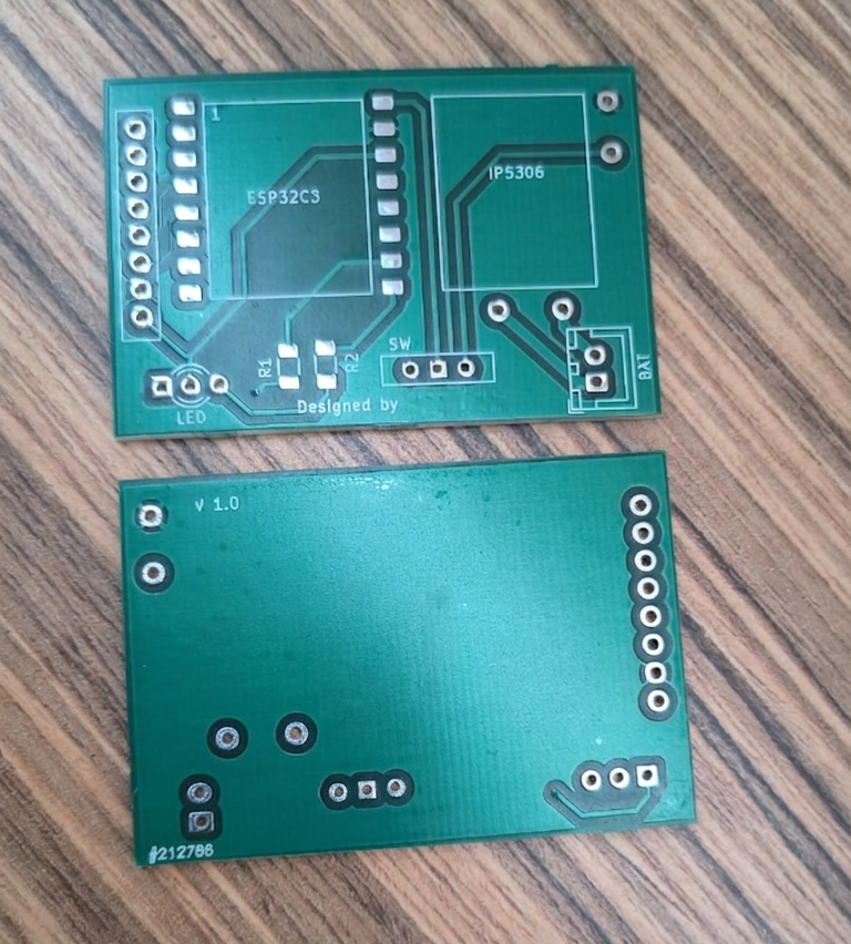
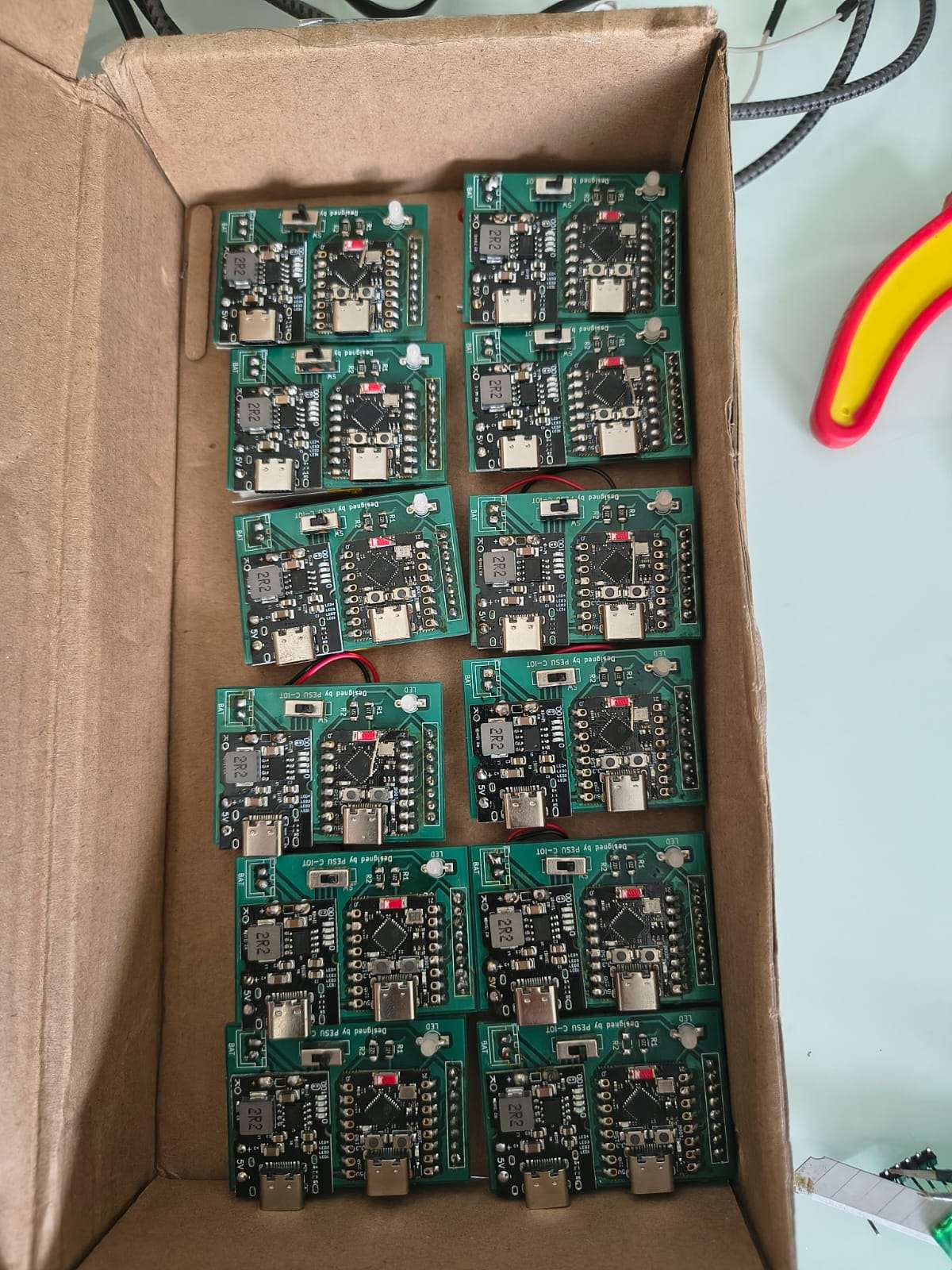
5. Custom PCB (v1.0)
.png)
.png)
| Spec | Value |
|---|---|
| Layers | 2-layer FR4 |
| Approx. dimensions | ~35–40 mm × ~55–60 mm (compact enough to fit the 3D-printed strap enclosure) |
| Key footprints | ESP32-C3 module, MPU6050 (or compatible IMU footprint), IP5306, 10-pin header (left edge), SW (power switch), BAT pads, LED + R1/R2 |
| Mounting | Two corner mounting holes, fits directly into the matching 3D-printed shell |
| Revision marking | Silkscreened "v1.0" + board ID number on the rear copper layer (visible in the photographed boards) |
| Role | Consolidates every per-node component from the original two-board prototype onto one repeatable, manufacturable board |
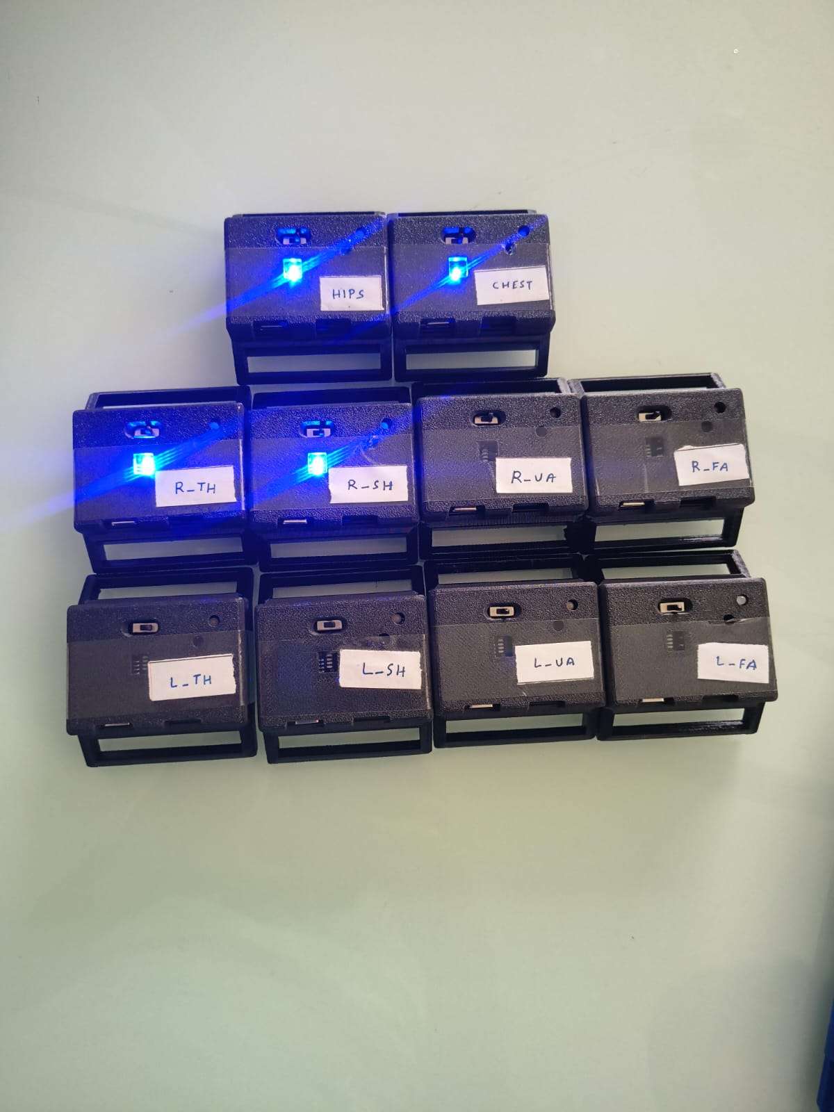
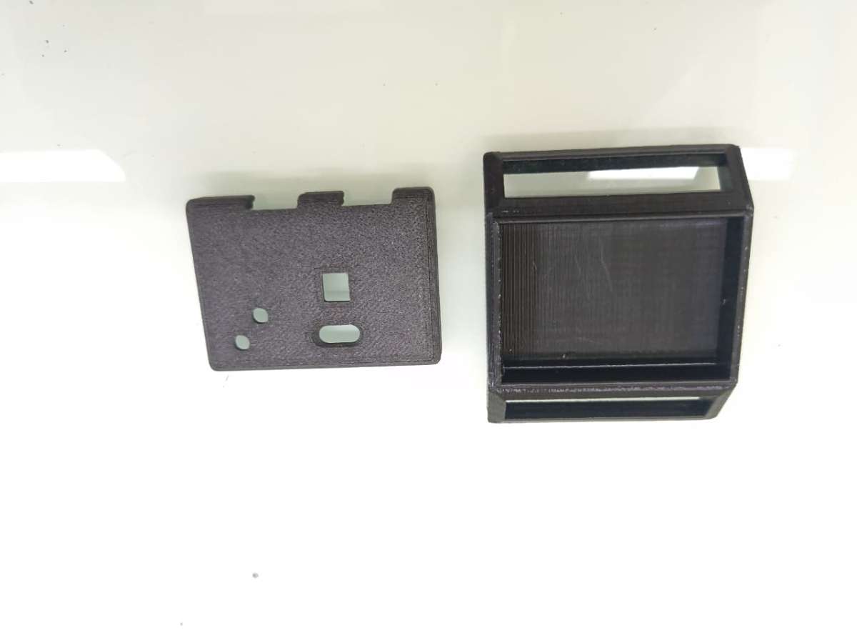
6. 3D-Printed Enclosure

.png)
| Spec | Value |
|---|---|
| Material (typical) | PLA or PETG |
| Features | Cut-out window for the status LED, slot for the power switch, strap-mount tabs front and back |
| Labeling | Each enclosure hand-labeled by body segment (HIPS, CHEST, R-TH, R-SH, R-UA, R-FA, and L- mirrors) for fast, error-free donning |
| Role | Protects the PCB and battery, and provides the mechanical interface to the body strap |
7. Strap / Mounting Hardware
.jpeg)
| Spec | Value |
|---|---|
| Material | Woven nylon/Velcro-loop strap, adjustable length |
| Mounting | Hook-and-loop closure, sized differently per limb (longer for thighs/hips, shorter for forearms) |
| Role | Secures each node snugly and repeatably to the same body landmark every time the suit is worn — critical for the T-pose calibration step to remain valid session to session |
- Arduino IDE / ESP-IDF — firmware for each ESP32-C3 node (I2C sensor read, DMP/quaternion computation, Wi-Fi or serial streaming)
- C++ / CMake — desktop visualizer application (
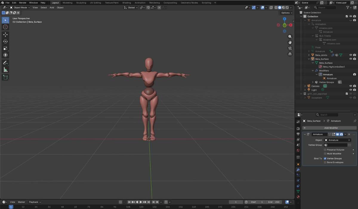
renderer.cpp,gltf_model.cpp) - glTF (
human.glb) — rigged 3D humanoid model used as the on-screen avatar - CSV logging pipeline — per-frame quaternion capture for offline playback and comparison (
run_001.csv…run_005.csv) - KiCad (or equivalent EDA tool) — custom PCB design for the consolidated ESP32-C3 + IP5306 node board
- VS Code — firmware and visualizer development environment
Step-by-Step: How It Was Built
Phase A — Design & Prototype
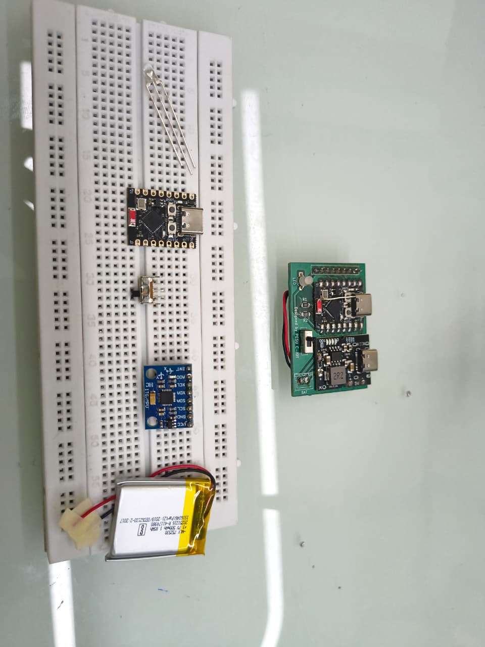
Step 1 — Breadboard proof of concept Start with one bare ESP32-C3 dev board and one breakout MPU6050 module. Wire SDA → GPIO8, SCL → GPIO9, VCC → 3.3V, GND → GND. Flash a basic I2C scanner sketch first to confirm the MPU6050 answers at address 0x68. This single wrist-taped prototype is what validates the sensing concept before committing to ten custom boards.
Step 2 — Bring up the DMP and confirm clean quaternion output Load an MPU6050 DMP library (e.g. the I2Cdevlib/MPU6050_DMP6 example as a base), initialize the DMP, and print live (w, x, y, z) quaternions to serial. Rotate the board by hand through all three axes and confirm the values stay within ||q|| ≈ 1 and respond smoothly with no flips — this is the sanity check that the sensing layer itself is reliable before any calibration logic is added.
Step 3 — Design the consolidated schematic In your EDA tool (e.g. KiCad), lay out a schematic that merges the dev-board + breakout-module wiring into one circuit: ESP32-C3 module, MPU6050 on dedicated I2C pads, IP5306 wired per its reference application circuit (BAT+/BAT− to the Li-Po, 5V IN from USB, 5V OUT boosting into the ESP32-C3's 3.3V regulator), a status LED with current-limiting resistor (R1), a second resistor (R2) for the IP5306's LED-driver/key strap configuration, a power slide switch (SW), and a 10-pin header for programming/debug access.
Step 4 — Lay out and fabricate the PCB Route the schematic onto a compact 2-layer board (~35–40 mm × ~55–60 mm), keeping the IMU footprint close to board center to minimize lever-arm error on the body, and keeping the LED visible through where the enclosure window will sit. Silkscreen a version mark (v1.0) and a unique board ID for traceability across ten boards. Send the Gerbers out for fabrication.
Phase B — Assemble & Bring Up Hardware
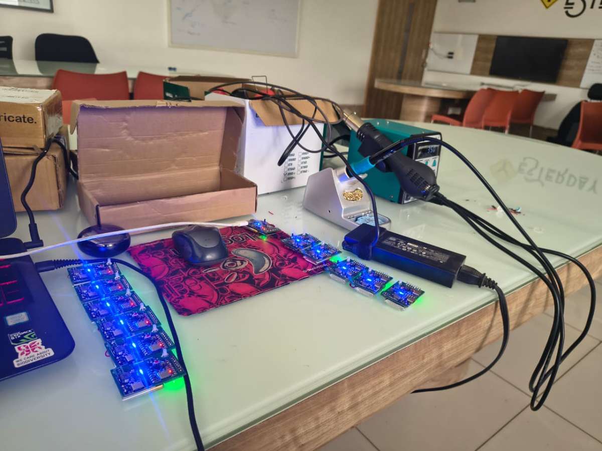
Step 5 — Solder and bring up one board first Hand-solder (or reflow) a single populated board before committing to all ten. Power it from a bench supply or USB before connecting a battery, and verify with a multimeter that the IP5306's boost output sits at a clean ~5V and that the ESP32-C3's 3.3V rail is stable.
Step 6 — Flash and smoke-test board #1 Flash the same DMP firmware from Step 2 onto the new board and re-run the rotate-and-watch-serial sanity check. Confirm the LED behaves as intended (power indication / streaming indication) and that the power switch cleanly cuts power.
Step 7 — Batch-assemble the remaining nine boards Repeat Steps 5–6 for the remaining boards. Burn in each board for a few minutes under power before sealing it into an enclosure — catching a bad solder joint now is much easier than after it's strapped to a body and mid-capture.
Step 8 — 3D-print and assemble enclosures Print ten enclosure shells with a cut-out aligned to each board's LED position and a slot for the slide switch. Mount each PCB and battery inside, close the shell, and label it by body segment (HIPS, CHEST, R-TH, R-SH, R-UA, R-FA, and the L- mirrors) so the suit can be put on quickly and without guesswork.
Step 9 — Attach straps Fit each enclosure to its Velcro/nylon strap — longer adjustable straps for hips/thighs/chest, shorter ones for forearms/upper arms — so every node can be cinched snugly and consistently against the same landmark every time the suit is worn.
Phase C — Firmware & Network
Step 10 — Write the per-node streaming firmware Extend the bring-up firmware so each node, after DMP init, continuously packages {label, quaternion[w,x,y,z], frame count/timestamp} and sends it out — over Wi-Fi/WebSocket, serial, or however your transport is configured — at the target ~50 Hz rate. Assign each node's unique body-segment label in firmware (or via a config flash at programming time) so the host always knows which board sent which packet.
Step 11 — Build the host-side ingestion + CSV logger On the PC side, write the receiver that listens for all ten nodes, timestamps each incoming frame, and appends it to a structured CSV (one row per timestamp, one quaternion block per body segment, plus an event column for calibration milestones like CALIBRATED_ALL). This logger should run independently of the 3D visualizer so a session can always be captured even if rendering is off.
Phase D — Calibration
Step 12 — Implement and run still calibration With all ten nodes laid flat and stationary, trigger the still-calibration routine: each node samples several iterations of accelerometer/gyroscope data, computes the mean bias against a known reference (a_ref = [0,0,1g]), and writes the correction into the sensor's offset registers. Confirm via serial/log output that all ten nodes report stillCalibrated = true before moving on.
Step 13 — Run T-pose calibration With the suit worn, send the "start T-pose calibration" trigger and hold a T-pose for ~30 seconds while each node streams continuously. The host averages roughly 1,000 samples per node into a reference quaternion, normalizes it, and stores it. From this point on, every incoming quaternion is corrected by q_relative = q_ref* ⊗ q_now before being used anywhere downstream.
Phase E — Visualization & Validation
Step 14 — Build and run the C++ visualizer Configure the CMake project, load the rigged human.glb model, and map each of the ten body-segment labels to its corresponding bone in the skeleton hierarchy. Feed it either live streamed data or a recorded CSV and confirm bone transforms update smoothly at the target frame rate with no visible jitter or flipping at extreme joint angles.
Step 15 — End-to-end dry run Put the full suit on, run through still calibration → T-pose calibration → a range of test movements (arm raises, squats, torso twists), and confirm the on-screen avatar visually tracks the real movement in real time while the CSV logger captures the same session to disk.
Step 16 — Benchmark against a reference system If available, run the same movement sequence wearing both MotionSync and a reference system (e.g. Movella DOT), log both, and compare quaternion trajectories frame-by-frame (this is exactly what the MovementComparision tooling exists for) to quantify the suit's real-world angular accuracy.
Working Principle
At its core, MotionSync solves one problem ten times over and then stitches the results back together: "what is this one body segment's 3D orientation, right now, relative to its parent joint?"
1. Sensing layer — turning raw motion into a stable quaternion
Each MPU6050 outputs raw 3-axis acceleration and 3-axis angular velocity at high rate. Used alone, accelerometer data is noisy and gyroscope data drifts over time — neither is trustworthy by itself. The MPU6050's onboard Digital Motion Processor (DMP) fuses both streams internally and outputs a single, stable unit quaternion q = w + xi + yj + zk describing that node's orientation in 3D space, with ||q|| = 1. Doing this fusion on the sensor itself (rather than in software on the host PC) keeps each node self-contained and keeps the wireless/serial payload tiny — just four floats and a timestamp per frame, no raw sensor data to transmit at all.
2. Calibration layer — removing bias and aligning to the body
Two corrections happen before a quaternion is trustworthy:
- Still calibration: with the node lying flat, the firmware samples several iterations of accelerometer and gyroscope data, computes the mean bias against a known-flat reference, and writes that offset directly into the sensor's hardware offset registers. From then on, every raw reading is automatically bias-corrected on-chip.
- T-pose calibration: every body is shaped differently, and a strap can sit at a slightly different angle each time it's worn. Rather than hand-tuning ten offsets, the wearer simply holds a T-pose for ~30 seconds. The system averages roughly 1,000 samples per node into a single reference quaternion, then normalizes it. Every subsequent frame is corrected by multiplying it by the conjugate of that reference quaternion (
q_relative = q_ref* ⊗ q_now) — which mathematically cancels out exactly how the sensor happens to sit on the body, leaving only the change in orientation from the calibration pose.
This is what lets the same hardware suit be strapped onto a different person, in a slightly different position, and still produce correct, repeatable joint angles within a 30-second setup.
3. Skeletal reconstruction — going from 10 numbers to one moving body
A real body doesn't move as ten independent points — a forearm rotates relative to the upper arm, which rotates relative to the chest, which rotates relative to the hips. MotionSync's renderer walks the skeleton from the root outward:
- For the root joint (HIPS), the corrected sensor quaternion is the bone's local rotation.
- For every other joint, the local rotation is computed as
q_local = (q_parent)⁻¹ ⊗ q_global— i.e. "how is this segment oriented, given how its parent is already oriented?" - Each local rotation is then combined with the 3D model's bind pose quaternion to get the bone's final transform, normalized, and applied to the rigged
human.glbskeleton.
The result is that errors don't "stack" in a visually broken way, and a single arm raising doesn't accidentally rotate the whole torso — exactly the behavior a real skeleton has.
4. Visualization & logging — seeing it and proving it
The C++ renderer applies all ten bone transforms at the suit's native streaming rate (target ≈ 50 Hz) so motion on screen looks smooth rather than stepped. In parallel, every frame is appended to a structured CSV log with an event column flagging calibration checkpoints (e.g. CALIBRATED_ALL) — meaning every capture session is automatically also a dataset, ready to be replayed, plotted, or diffed frame-by-frame against another system's log for accuracy comparison.
Pipeline, end to end
Raw IMU motion → on-sensor DMP fusion → quaternion → bias-corrected (still calibration) → reference-normalized (T-pose calibration) → parent-relative local rotation → bind-pose-adjusted final bone quaternion → applied to rigged glTF skeleton (rendered) and appended to CSV (logged).
Because every node runs the exact same firmware and hardware, the system is modular by design — nodes can be added or removed depending on whether full-body, upper-body-only, or single-limb tracking is needed, without touching the rest of the pipeline.
How MotionSync Compares
| Optical (Vicon/OptiTrack) | Commercial IMU suit (Movella, Rokoko, SlimeVR) | MotionSync | |
|---|---|---|---|
| Typical cost | $50,000 – $100,000+ | $1,000 – $15,000+ | ≈ ₹6,500–10,000 (~$80–120) for the full 10-node suit |
| Setup | Multi-camera rig, fixed studio space | Plug-and-play, but locked hardware/software | Strap on, 2-stage self-calibration (~1 min) |
| Portability | None — fixed installation | High | High — fully wireless, battery-powered nodes |
| Customizability | None (closed system) | Low (closed firmware/hardware) | High — open hardware, firmware, and renderer; nodes can be added/removed/repaired |
| Data ownership | Vendor software/format | Vendor app, often cloud-tied | Raw CSV + open glTF pipeline — fully owned, inspectable data |
| Best fit | Film studios, pro research labs | Studios, serious indie creators |
Application Prospects & Real-World Usefulness
Rehabilitation & physiotherapy — Clinics and home-care setups can track joint range-of-motion and gait symmetry during recovery exercises without needing a hospital-grade motion lab. Because every session is logged as a timestamped CSV, a physiotherapist can quantitatively track a patient's improvement week over week instead of relying on visual judgment alone.
Elderly fall-risk monitoring — Subtle changes in gait and postural transitions are early indicators of fall risk in older adults. A suit this cheap is the difference between "no monitoring at all" and "regular, low-cost movement screening" in home or community-care settings.
Sports biomechanics for non-elite athletes — School and college sports programs that can't afford studio biomechanical analysis can use MotionSync to spot form issues (joint angles during a throw, squat, or sprint stride) that are normally only available to professionally funded teams.
Indie game development & animation — Independent studios and student animators can capture believable reference motion for character rigs without licensing expensive MoCap time, directly lowering the barrier to producing professional-feeling character animation.
Embedded systems & robotics education — As a teaching platform, MotionSync is a complete, hands-on case study in IMU sensor fusion, quaternion math, wireless sensor networks, custom PCB design, and real-time 3D rendering — all in one project, at a price point a student lab can actually afford to build ten or twenty of.
Human-robot motion mirroring — The same quaternion stream that drives a glTF avatar can drive a robotic arm or animatronic rig, opening a path toward low-cost teleoperation and gesture-based robot control.
Productization & entrepreneurship potential
- The hardware is already at the "single custom PCB per node" stage — the step from there to small-batch manufacturing (panelized PCB orders, injection-molded enclosures instead of 3D-printed ones) is incremental, not a redesign.
- A tiered product line is a natural fit: a 4-node "upper body" kit for animators/gamers, a 6–8-node "limb tracking" kit for physiotherapy, and the full 10-node suit for complete full-body capture — all sharing one node design.
- The CSV-first, comparison-oriented data pipeline is also licensable on its own as a validation/QA tool for other low-cost motion-tracking hardware, independent of the suit itself.
Technology Practicality & Cost-Effectiveness
- Per-node bill of materials centers on three commodity parts — ESP32-C3, MPU6050, IP5306 — each costing a few hundred rupees, keeping a 10-node suit in the ₹6,500–10,000 (~$80–120) range, against $1,000+ per sensor for commercial alternatives.
- Power efficiency: the IP5306 handles both charging and 5V boost regulation in one chip, removing the need for a separate regulator and extra board space per node — the same efficient approach commercial trackers like SlimeVR use.
- On-sensor fusion (DMP) means each node only ever needs to transmit a handful of floats per frame, not raw 6-axis data — lower bandwidth, lower power, simpler wireless stack.
- Self-calibrating: no factory calibration step or vendor software lock-in — still calibration and T-pose calibration run automatically each session, on any body.
- Modular and repairable: a faulty node is a single small PCB, not a write-off of an entire suit — directly reducing long-term cost of ownership versus a sealed commercial unit.
.png)
1st prototype
2nd prototype
Sentralized charging system
.jpeg)
Demo video 1
Demo video 2
Future Scope
- Migrate from MPU6050 to a more drift-resistant IMU (e.g. ICM-42688, as used in SlimeVR Gen2) for longer sessions with less orientation drift.
- Move to a hub-and-spoke radio topology (ESP-NOW or a dedicated 2.4 GHz link) instead of per-node Wi-Fi, cutting latency and node power draw.
- Extend validation from static poses to dynamic activities — walking, running, sports-specific motion.
- Explore sparse-sensor reconstruction (machine learning–based pose inference from fewer than 10 nodes) to reduce hardware cost further without losing tracking fidelity.
Github link-- https://github.com/Shreerama8/BodySync-A-Cost-Effective-Modular-IMU-Sensor-Suit-for-Real-Time-Human-Body-Motion-Tracking.git
Firmware Design and Working Principle
The firmware for each wearable BodySync node is developed using the Arduino framework on the ESP32-C3 microcontroller. It is responsible for sensor initialization, calibration, wireless communication, and real-time transmission of orientation data. Every sensor node executes identical firmware, with only the body segment label (such as HIPS, CHEST, L_UA, R_UA, L_TH, etc.) changed to uniquely identify its position on the human body.
1. Library Initialization
The firmware begins by including the required libraries:
- WiFi.h – Establishes wireless communication.
- WiFiUdp.h – Enables UDP multicast data transmission.
- Wire.h – Provides I²C communication.
- I2Cdev.h – Simplifies communication with the MPU6050.
- MPU6050_6Axis_MotionApps612.h – Accesses the Digital Motion Processor (DMP) for quaternion computation.
These libraries allow the ESP32-C3 to communicate with the IMU sensor and transmit processed orientation data over Wi-Fi.
2. System Configuration
Several configuration parameters are defined at the beginning of the program.
- Wi-Fi SSID and password for network connectivity.
- UDP multicast IP address and communication port.
- A unique sensor label identifying the body location of the node.
- GPIO pins used for status LEDs.
Each wearable node shares the same firmware architecture, differing only in the assigned sensor label.
3. Wi-Fi Connection
The firmware automatically connects the ESP32-C3 to the configured wireless network.
During connection:
- The red LED blinks continuously.
- If the connection is successful, the device stores its IP address.
- If the connection fails within the timeout period, the firmware retries automatically during the main execution loop.
This mechanism ensures reliable operation even if the wireless connection is temporarily interrupted.
4. Power-On Self-Test
Immediately after power-up, the firmware executes a startup indication sequence.
- Red and green LEDs blink alternately for approximately 5.5 seconds.
- This visually confirms successful booting and verifies LED functionality.
- After completion, both LEDs are turned OFF before initialization continues.
This startup sequence helps users verify that the node has powered on correctly.
5. MPU6050 Initialization
After the power-on sequence, the firmware initializes the MPU6050 Inertial Measurement Unit.
The initialization process establishes I²C communication between the ESP32-C3 and the MPU6050 and prepares the sensor for calibration.
6. Sensor Calibration
To improve measurement accuracy, the firmware performs automatic calibration immediately after initialization.
Gyroscope Calibration
The gyroscope is calibrated while the sensor remains completely stationary.
This removes the inherent bias present in angular velocity measurements.
Accelerometer Calibration
The accelerometer is calibrated while the sensor is placed on a flat surface.
This compensates for offset errors and establishes an accurate gravity reference.
Automatic calibration significantly improves long-term stability and reduces orientation drift.
7. DMP Initialization
Once calibration is completed, the firmware enables the MPU6050 Digital Motion Processor (DMP).
The DMP performs internal sensor fusion using accelerometer and gyroscope data to directly generate quaternion values.
Advantages include:
- Reduced ESP32 computational load
- Improved orientation accuracy
- Lower sensor drift
- Stable real-time motion estimation
If DMP initialization fails, the firmware enters an error state where the red LED rapidly blinks to indicate a hardware fault.
8. Continuous Sensor Operation
During normal operation, the firmware continuously performs the following tasks:
- Monitor Wi-Fi connectivity.
- Read quaternion data from the MPU6050 DMP.
- Package the orientation data.
- Transmit data to the visualization software.
- Indicate normal operation using a heartbeat LED.
The firmware executes these tasks continuously to provide uninterrupted real-time motion tracking.
9. Wi-Fi Reconnection
The firmware continuously monitors the wireless connection.
If the Wi-Fi connection is lost:
- Data transmission is temporarily paused.
- The firmware automatically reconnects to the configured network.
- Streaming resumes immediately after reconnection.
This ensures reliable long-duration operation without manual intervention.
10. Heartbeat Indicator
A periodic heartbeat LED provides visual feedback that the node is operating normally.
- Every second the red LED briefly turns ON for approximately 150 ms.
- This confirms that the firmware is actively running and transmitting data.
11. FIFO Buffer Management
The MPU6050 stores processed orientation data in its internal FIFO memory.
The firmware continuously checks the FIFO buffer.
If the buffer overflows:
- The FIFO is automatically reset.
- Data acquisition resumes without restarting the system.
This prevents corrupted measurements and maintains stable long-term operation.
12. Quaternion Acquisition
The firmware retrieves quaternion values directly from the MPU6050 Digital Motion Processor.
Each quaternion contains four components:
- w
- x
- y
- z
Quaternions provide a robust representation of three-dimensional orientation without suffering from gimbal lock, making them ideal for motion capture applications.
13. Data Packet Formation
Each sensor node creates a compact transmission packet containing:
- Sensor Label
- Quaternion w
- Quaternion x
- Quaternion y
- Quaternion z
Example:
HIPS,0.9987,0.0152,-0.0311,0.0428This compact format minimizes communication latency while maintaining high orientation accuracy.
14. Wireless Data Transmission
The orientation packet is transmitted using UDP multicast over Wi-Fi.
UDP multicast enables multiple visualization clients to receive the same motion data simultaneously with minimal communication overhead.
The firmware transmits new orientation updates approximately every 15 milliseconds, corresponding to a refresh rate of approximately 66 Hz, ensuring smooth real-time motion visualization.
15. Serial Debugging
For debugging purposes, the firmware outputs one status message every 100 transmitted packets through the serial monitor.
This feature assists developers during testing while minimizing unnecessary serial communication overhead.
Code
5. Firmware Implementation
The firmware for the BodySync wearable node is developed using the Arduino IDE for the ESP32-C3 microcontroller. It initializes the MPU6050 IMU, performs sensor calibration, connects to Wi-Fi, acquires quaternion orientation data using the Digital Motion Processor (DMP), and transmits it wirelessly using UDP multicast.
5.1 Required Libraries
The firmware begins by including the required libraries for wireless communication, I²C communication, and MPU6050 DMP functionality.
#include <WiFi.h>
#include <WiFiUdp.h>
#include <Wire.h>
#include "I2Cdev.h"
#include "MPU6050_6Axis_MotionApps612.h"
Explanation
| Library | Purpose |
|---|---|
| WiFi.h | Connects ESP32-C3 to Wi-Fi |
| WiFiUdp.h | Sends sensor data via UDP |
| Wire.h | Enables I²C communication |
| I2Cdev.h | Simplifies MPU6050 communication |
| MPU6050_6Axis_MotionApps612.h | Enables DMP and quaternion calculation |
5.2 Wi-Fi Configuration
The ESP32-C3 connects to the local wireless network using the following configuration.
const char* ssid = "*******";
const char* password = "*******";

const char* multicast_ip = "239.0.0.1";
const unsigned int port = 5005;

const char* SENSOR_LABEL = "HIPS";
Explanation
- SSID and Password connect the node to the Wi-Fi network.
- UDP Multicast enables simultaneous communication with multiple clients.
- SENSOR_LABEL uniquely identifies each wearable node (e.g., HIPS, CHEST, R_FA).
5.3 Hardware Initialization
The microcontroller initializes Serial communication, I²C, and status LEDs.
Serial.begin(115200);
Wire.begin(8,9);

pinMode(LED_RED, OUTPUT);
pinMode(LED_GREEN, OUTPUT);
Explanation
- Serial is used for debugging.
- GPIO8 and GPIO9 act as SDA and SCL for the MPU6050.
- LEDs indicate system status.
5.4 Startup LED Sequence
During power-up, the firmware performs a self-test by blinking LEDs alternately.
while (millis() - start < 5500)
{
    redOn = !redOn;

    digitalWrite(LED_RED,
                 redOn ? LOW : HIGH);

    digitalWrite(LED_GREEN,
                 redOn ? HIGH : LOW);
}
Explanation
This confirms that:
- ESP32-C3 booted successfully.
- LEDs are functioning.
- Firmware execution has started.
5.5 MPU6050 Initialization
The IMU is initialized before calibration.
mpu.initialize();
Explanation
This establishes communication between the ESP32-C3 and the MPU6050 sensor.
5.6 Sensor Calibration
Automatic calibration removes sensor bias.
mpu.CalibrateGyro(6);

mpu.CalibrateAccel(6);
Explanation
Gyroscope calibration removes angular velocity offsets.
Accelerometer calibration removes acceleration bias.
This greatly improves orientation accuracy.
5.7 Wi-Fi Connection
The firmware automatically connects to Wi-Fi.
WiFi.begin(ssid,password);

while(WiFi.status()!=WL_CONNECTED)
{
    Serial.print(".");
}
Explanation
The ESP32 continuously attempts to connect until successful.
Once connected,
- IP Address is assigned.
- Wireless communication begins.
5.8 DMP Initialization
The Digital Motion Processor is enabled.
if(mpu.dmpInitialize()==0)
{
    mpu.setDMPEnabled(true);
}
Explanation
The DMP performs sensor fusion internally and directly outputs quaternion orientation values, reducing the computational load on the ESP32.
5.9 Main Program Loop
The loop continuously performs
- Wi-Fi monitoring
- Sensor reading
- Data transmission
void loop()
{
    if(WiFi.status()!=WL_CONNECTED)
    {
        connectWiFi();
        return;
    }

    if(!mpu.dmpGetCurrentFIFOPacket(fifoBuffer))
        return;
}
Explanation
The firmware continuously checks
- Wi-Fi connection
- New sensor data
- FIFO status
before processing the orientation.
5.10 Reading Quaternion
Quaternion values are extracted from the DMP.
Quaternion q;

mpu.dmpGetQuaternion(
        &q,
        fifoBuffer
);
Explanation
Quaternion components
q.w
q.x
q.y
q.z
represent the complete 3D orientation of the wearable node.
Unlike Euler angles, quaternions eliminate gimbal lock.
5.11 Creating Data Packet
The orientation is converted into a compact packet.
char payload[64];

snprintf(payload,
         sizeof(payload),
         "%s,%.4f,%.4f,%.4f,%.4f",
         SENSOR_LABEL,
         q.w,
         q.x,
         q.y,
         q.z);
Example Output
HIPS,0.9987,0.0152,-0.0311,0.0428
Explanation
Each packet contains
- Sensor Name
- Quaternion W
- Quaternion X
- Quaternion Y
- Quaternion Z
5.12 UDP Transmission
The packet is transmitted wirelessly.
udp.beginPacket(multicast_ip,port);

udp.print(payload);

udp.endPacket();
Explanation
UDP Multicast provides
- Low latency
- Lightweight communication
- Multiple receivers
- Real-time streaming
5.13 Heartbeat Indicator
The firmware periodically flashes the red LED.
digitalWrite(LED_RED,LOW);

delay(150);

digitalWrite(LED_RED,HIGH);
Explanation
This heartbeat confirms that the wearable node is operating normally and continuously transmitting data.
5.14 FIFO Overflow Protection
The firmware prevents buffer overflow.
if(mpu.getFIFOCount()>=1024)
{
    mpu.resetFIFO();
}
Explanation
Resetting the FIFO prevents corrupted sensor readings during long-term operation.
5.15 Firmware Workflow
Power ON
      │
      ▼
Initialize ESP32-C3
      │
      ▼
Initialize MPU6050
      │
      ▼
Calibrate Gyroscope
      │
      ▼
Calibrate Accelerometer
      │
      ▼
Connect to Wi-Fi
      │
      ▼
Initialize DMP
      │
      ▼
Read Quaternion
      │
      ▼
Create UDP Packet
      │
      ▼
Transmit Wirelessly
      │
      ▼
Repeat at ~66 Hz
Firmware Features
- Automatic sensor initialization
- Self-calibration for improved accuracy
- DMP-based quaternion computation
- Real-time Wi-Fi communication
- UDP multicast transmission
- Automatic Wi-Fi reconnection
- FIFO overflow protection
- Heartbeat LED for status indication
- Scalable firmware supporting multiple BodySync sensor nodes