



Battery
│
▼
Buck Converter
│
▼
Control Circuit (calibration and coding!)
▲
│
LDR Sensor ready
│
▼
LED Indicators placed
Step 1: Planning the Design
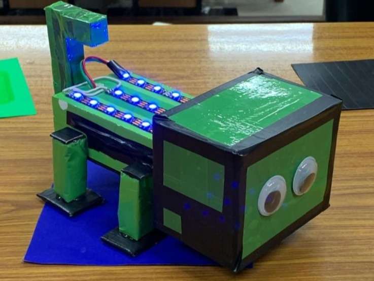
We first designed a robot that resembles a chameleon. The main goal was to make it detect light using an LDR (Light Dependent Resistor) and display its response using LEDs. The body was built using cardboard, foam sheets, and colored paper to give it a creative appearance.
Step 2: Collecting the Components
The following components were used:
- LDR (Light Dependent Resistor)
- LEDs
- Buck Converter (LM2596 or similar)
- Battery Pack
- Microcontroller (Arduino/Nano or equivalent, if used)
- Resistors
- Connecting Wires
- Switch
- Cardboard/Foam Sheet for the body
- Glue Gun and Double-sided Tape
Step 3: Building the Chassis
The robot body was made using cardboard and foam sheets.
- A rectangular body was created.
- Four legs were attached for support.
- A tail and neck were added to resemble a chameleon.
- Decorative eyes were fixed to make the robot attractive.
Step 4: Installing the Electronics


7
The electronic components were mounted inside the robot.
- The LDR was placed where it could easily receive ambient light.
- LEDs were fixed on the robot's back to show the light response.
- The battery was connected through a buck converter to provide a stable operating voltage.
- All wires were neatly arranged inside the body.
Step 5: Programming (If a Microcontroller Was Used)
A simple program was written to:
- Read the value from the LDR.
- Compare it with a preset threshold.
- Turn the LEDs ON/OFF or change their brightness based on the surrounding light.
If no microcontroller was used, the LEDs were controlled directly through an analog LDR circuit.
Step 6: Testing the Robot
The robot was tested under different lighting conditions.
- In bright light, the LDR detected high light intensity and the LEDs responded accordingly.
- In dim light, the LDR resistance changed, causing a different LED output.
- The buck converter ensured a constant voltage, making the robot operate smoothly.
Step 7: Final Assembly
After successful testing:
- All components were secured inside the body.
- The cover was closed.
- The robot was decorated with green paper and eyes to resemble a real chameleon.


