

Step 1: Problem Identification
We began by identifying major challenges in rural transportation, such as overloading, lack of vehicle tracking, poor safety monitoring, absence of obstacle detection, and delayed emergency response. These issues often lead to accidents, cargo damage, and inefficient transport operations. Our goal was to develop a low-cost smart system capable of monitoring these parameters in real time and improving overall transportation safety.
Step 2: Selecting the Core Controller
The ESP32 microcontroller was chosen as the central processing unit because of its built-in Wi-Fi, powerful dual-core processor, low power consumption, and ability to interface with multiple sensors simultaneously. The ESP32 serves as the brain of the entire system, collecting data from sensors, processing information, generating alerts, and communicating with the dashboard.
Step 3: Designing the Sensor Network
To monitor different aspects of the cart, multiple sensors were integrated into the system.
A Load Cell combined with an HX711 amplifier was used to measure the weight carried by the cart and detect overload conditions.
An MPU6050 accelerometer and gyroscope module was added to monitor vibration, acceleration, tilt angle, and overall cart stability.
A Vibration Sensor was incorporated to detect excessive shocks, potholes, collisions, and rough road conditions.
A DHT11 sensor was used to measure temperature and humidity, ensuring that transported goods remain within safe environmental conditions.
An Ultrasonic Sensor was mounted at the front of the cart to detect nearby obstacles and reduce collision risks.
Step 4: Implementing GPS Tracking
A GPS module was integrated to provide real-time location information. The module continuously supplies latitude and longitude coordinates, enabling route tracking, movement monitoring, and improved transportation visibility. This allows operators to know the exact position of the cart at any time.
Step 5: Adding Emergency Communication
To ensure reliable communication in rural areas, a SIM800L GSM module was incorporated into the design. Whenever unsafe conditions such as overload, excessive vibration, abnormal tilt, collision risk, or environmental hazards are detected, the GSM module automatically sends SMS alerts to predefined users. This ensures rapid response even in locations with limited internet connectivity.
Step 6: Developing the User Interface
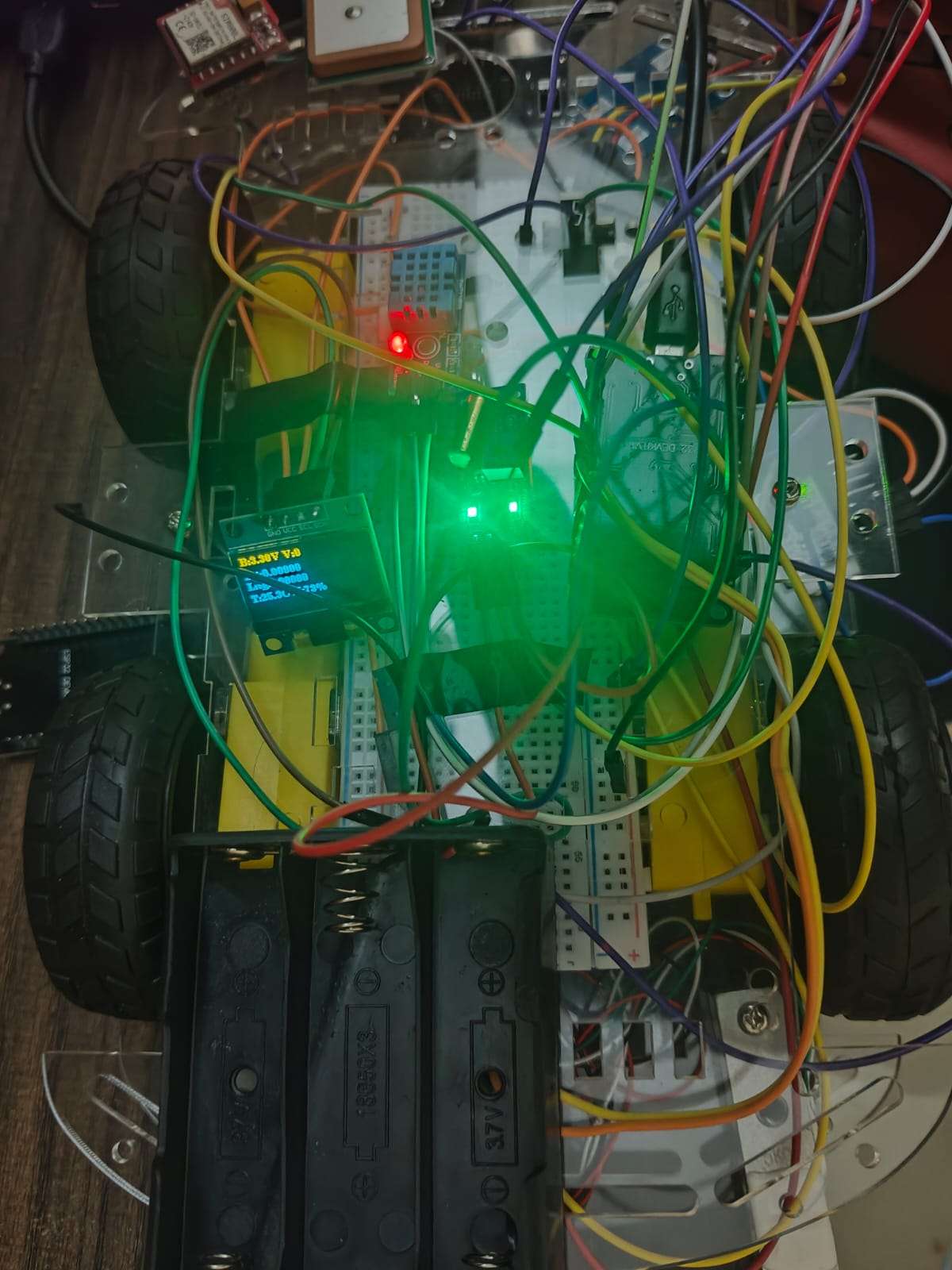
A 0.96-inch OLED display was added for local monitoring. It displays important information such as load, temperature, humidity, vibration status, obstacle distance, and GPS coordinates in real time.
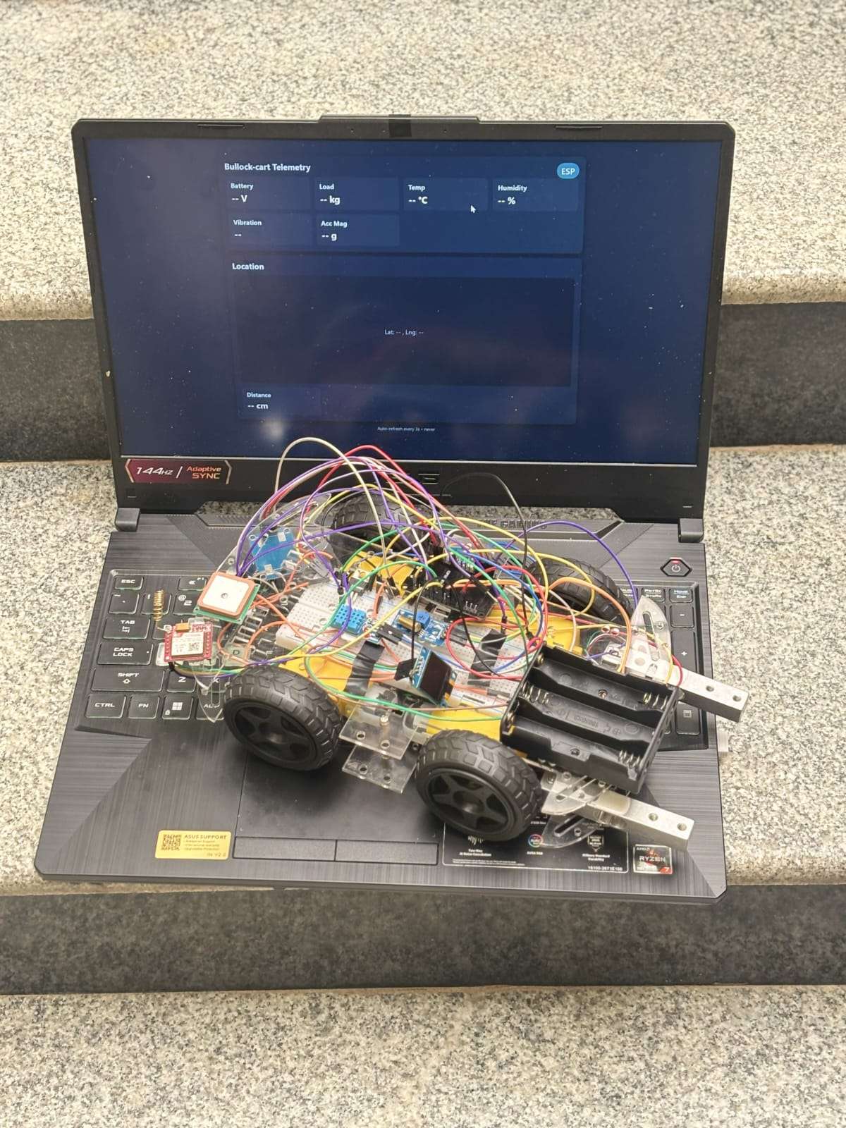
In addition, an IoT dashboard was developed to provide remote monitoring. The dashboard visualizes sensor data, displays alerts, tracks GPS location, and stores historical records for analysis.
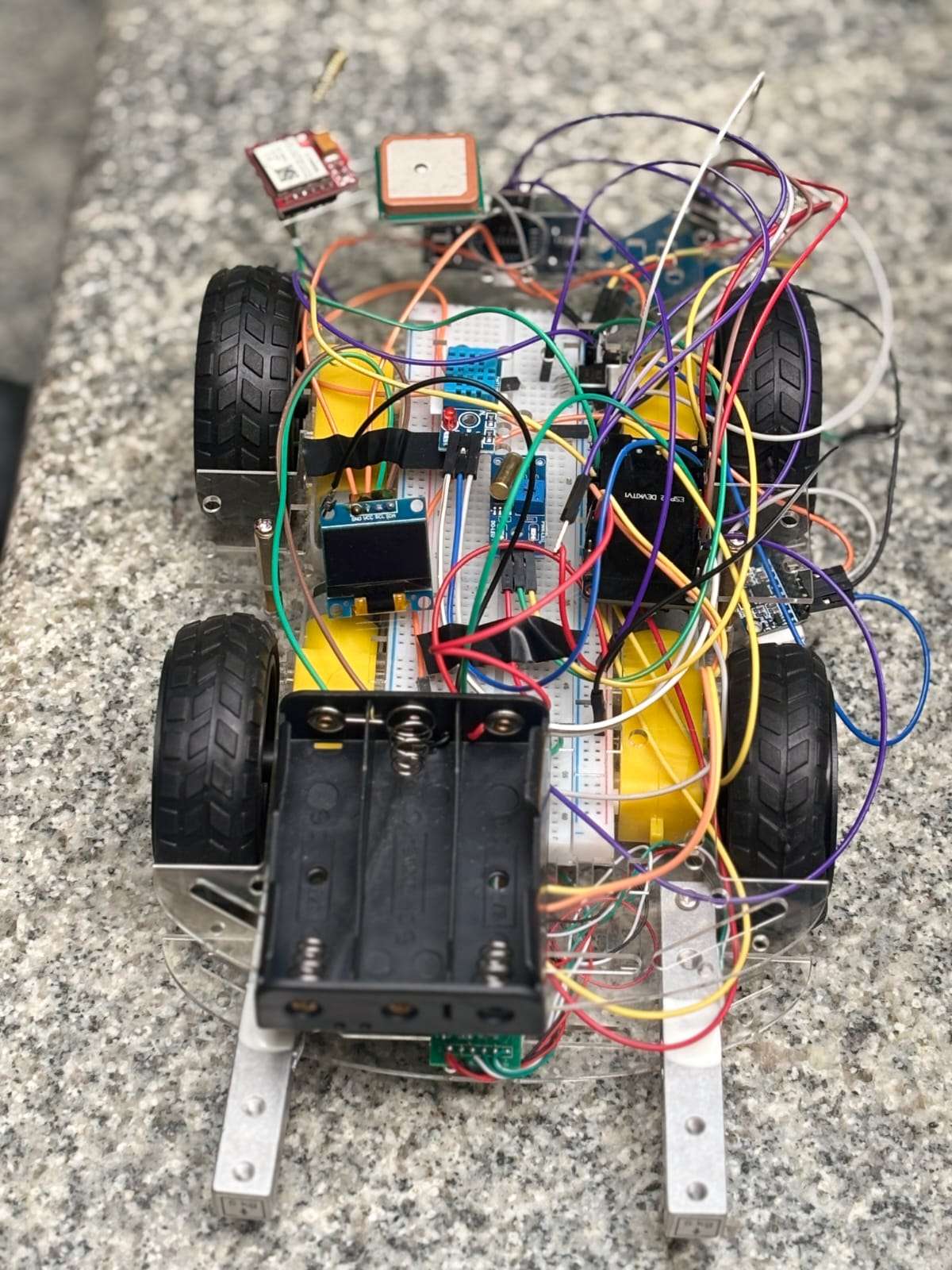
Step 7: Hardware Integration
After selecting all components, the hardware modules were interconnected with the ESP32. Each sensor was connected to the appropriate GPIO pins using communication protocols such as I2C, UART, and digital interfaces. Proper power regulation and grounding were implemented to ensure stable and reliable operation.
Step 8: Software Development
The system firmware was developed using Arduino IDE. Various libraries were integrated to support sensor communication, GPS processing, OLED display control, Wi-Fi connectivity, and GSM communication. The software continuously reads sensor data and manages all system operations.
Step 9: Data Processing and Analysis
The ESP32 continuously acquires data from all sensors and performs filtering, calibration, and processing. Sensor readings are analyzed against predefined thresholds to identify unsafe conditions. Noise reduction techniques and sensor fusion methods are used to improve measurement accuracy and reliability.
Step 10: Dashboard and Cloud Communication
Processed data is transmitted through Wi-Fi to the web-based dashboard. Users can monitor live values such as load, vibration, temperature, humidity, obstacle distance, and GPS location. The dashboard acts as a centralized platform for monitoring and decision-making.
Step 11: Alert Generation
The system continuously checks whether any parameter exceeds safe limits. If an abnormal condition is detected, warning messages are generated immediately. Alerts are displayed on the dashboard and SMS notifications are sent through the GSM module to inform users about potential risks.
Step 12: System Testing and Validation
The completed prototype was tested under various operating conditions. Tests were conducted for load monitoring, vibration detection, obstacle sensing, GPS tracking, dashboard responsiveness, and SMS communication. The results confirmed reliable operation, high alert accuracy, stable communication, and effective real-time monitoring.
Step 13: Final Working of the System
The final system operates in a continuous loop. Sensors collect data from the cart and its surroundings. The ESP32 processes this information and sends it to the dashboard. If all parameters remain within safe limits, monitoring continues normally. If unsafe conditions are detected, immediate alerts are generated and transmitted to users. This creates a smart, connected, and safety-aware transportation platform capable of improving rural mobility and agricultural logistics.