Video
DigiKey My-list
https://www.digikey.in/en/mylists/list/X3HV4BFFNM
I built this project by creating a complete live audio streaming system using two ESP32 boards. One ESP32 works as the transmitter with an INMP441 I²S microphone, and the other ESP32 works as the receiver with a MAX98357A I²S DAC and a speaker. Below is the step-by-step process I followed:
- Planned the Objective
My goal was to transmit live audio from a microphone to another device using Wi-Fi with low latency. I selected ESP32 because it supports I²S audio and Wi-Fi in one chip. - Collected All Components
I used two ESP32 development boards, an INMP441 microphone, a MAX98357A DAC module, a small speaker, jumper wires, and USB power cables. - Designed the System Workflow
The transmitter captures sound → converts it to digital using INMP441 → ESP32 sends the audio packets over Wi-Fi → receiver ESP32 gets the packets → MAX98357A converts them to analog → speaker plays the sound. - Made the Wiring Connections
I connected the INMP441 microphone to the transmitter ESP32 using I²S pins (WS, SCK, SD).
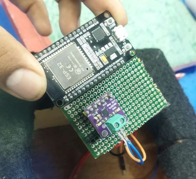
On the receiver side, I connected the MAX98357A DAC to the ESP32 using I²S pins (BCLK, LRC, DIN) and connected the speaker to the DAC. - Configured the Transmitter Code
On the first ESP32, I initialized the I²S microphone, set the sample rate, read audio data, and sent it continuously to the receiver’s IP address using UDP over Wi-Fi. - Configured the Receiver Code
On the second ESP32, I opened a UDP socket, received incoming audio packets, and fed them into the MAX98357A DAC using I²S output to play audio on the speaker. - Connected Both Devices to Wi-Fi
I connected both ESP32 boards to the same Wi-Fi network and set the receiver’s IP address inside the transmitter code. - Flashed and Tested the Setup
I uploaded the transmitter and receiver programs, powered both boards, spoke into the INMP441 microphone, and verified that the speaker played the live audio with low delay. - Improved Stability
I adjusted buffer sizes and packet lengths to reduce glitches and maintain smooth real-time audio streaming. - Documented the Final System
I prepared wiring diagrams, explanation notes, and testing results to complete the project submission:
Schematic
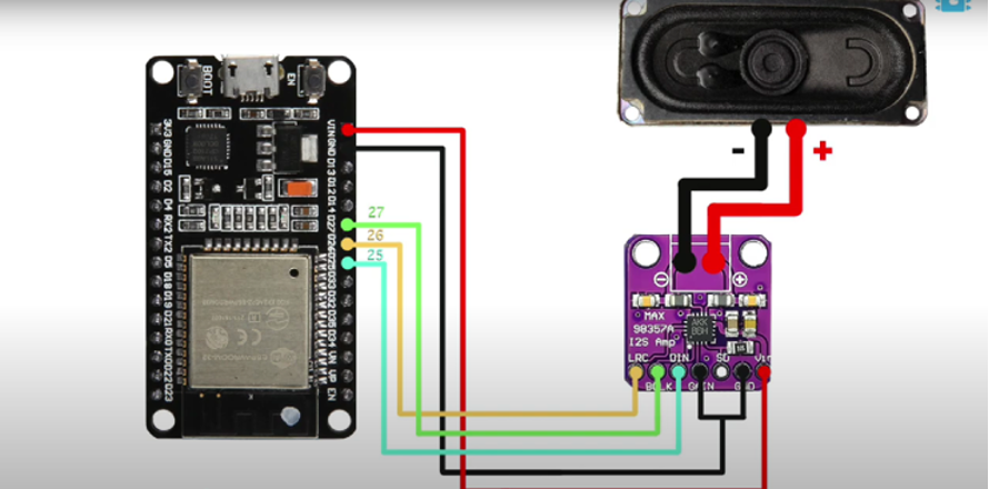
.png)
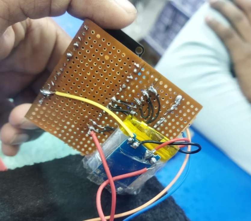
PCB Planning
.png)
Final Outcome