
Youtube video demo: Youtube
Step 1: Understanding the Game
The LCD acts like a two-lane race track.
- Top row = Lane 1
- Bottom row = Lane 2
A photon appears on one of the lanes and moves from left to right.
Controls
| Button | Function |
|---|---|
| Button A | Hit photon on top row |
| Button B | Hit photon on bottom row |
Rules
- Start with 3 lives.
- Hit the photon when it reaches the last columns.
- Successful hit = score increases.
- Miss = lose one life.
- Speed increases continuously.
- Game ends when all lives are lost.
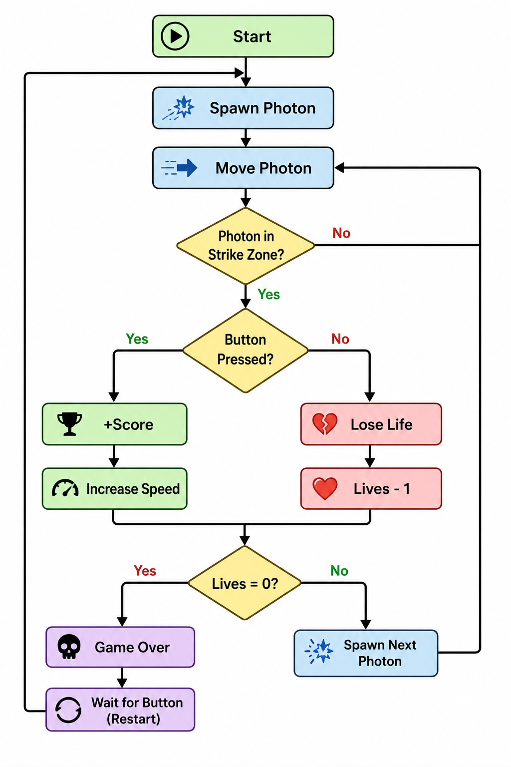
Step 2: How It Works
The ESP32:
- Generates a random lane.
- Creates a photon at column 0.
- Moves the photon every few milliseconds.
- Checks whether the player pressed the correct button.
- Updates score and lives.
- Increases speed after successful hits.
- Shows Game Over and waits for restart.
Step 3: Circuit Diagram
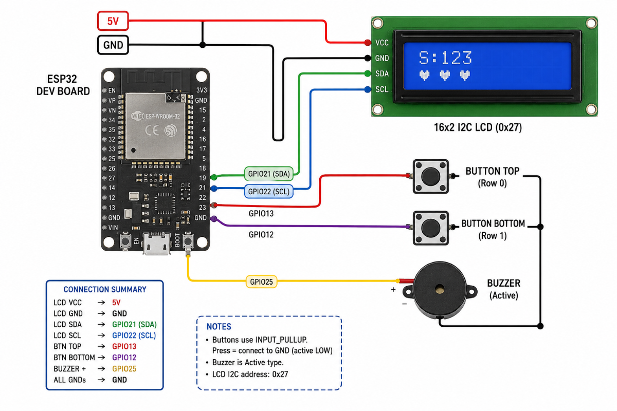
Connections
Buttons
| Button | ESP32 Pin |
|---|---|
| Top Lane Button | GPIO13 |
| Bottom Lane Button | GPIO12 |
Connect the other side of each button to GND.
Buzzer
| Buzzer | ESP32 |
|---|---|
| + | GPIO25 |
| - | GND |
LCD I2C Module
| LCD | ESP32 |
|---|---|
| VCC | 5V |
| GND | GND |
| SDA | GPIO21 |
| SCL | GPIO22 |
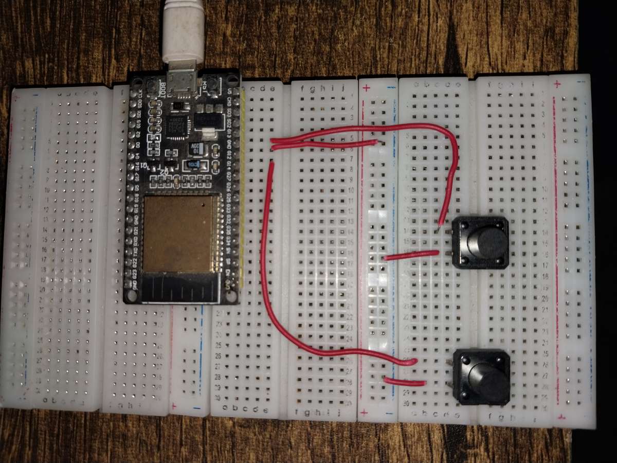
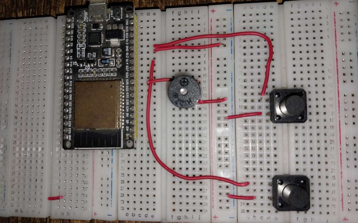
Step 4: Build the Hardware
- Place the ESP32 on the breadboard.
- Connect the LCD module.
- Add two push buttons.
- Connect one side of each button to GND.
- Connect the buzzer to GPIO25.
- Verify all wiring before powering the circuit.
Step 5: Create Custom Characters
Two custom LCD characters are used:
Photon Character
  *
 ***
*****
*****
 ***
  *
Heart Character
Used to display remaining lives.
* *
*****
*****
 ***
  *
These characters are stored inside the LCD memory using:
lcd.createChar();
Step 6: Initialize the System
During startup:
- Buttons are configured as INPUT_PULLUP.
- LCD is initialized.
- Backlight is enabled.
- Custom characters are loaded.
- Random number generator is seeded.
- First photon is spawned.
randomSeed(analogRead(34));
lcd.init();
lcd.backlight();
spawnPhoton();
Step 7: Photon Generation
A random lane is selected:
photonRow = random(0,2);
Possible values:
- 0 = Top lane
- 1 = Bottom lane
The photon starts from:
photonCol = 0;
Step 8: Photon Movement
The game uses a non-blocking timer based on:
millis()
Every few milliseconds:
photonCol++;
The photon moves one column to the right.
This makes animation smooth and responsive.
Step 9: Strike Zone Detection
The last columns of the LCD act as the strike zone:
bool inZone = (photonCol >= 13 && photonCol <= 15);
When the photon reaches this area, the player must press the correct button.
Step 10: Button Detection
Top button:
pressed(BTN_TOP)
Bottom button:
pressed(BTN_BOT)
Since INPUT_PULLUP is used:
LOW = Pressed
HIGH = Released
Step 11: Successful Hit
If the player presses the correct button inside the strike zone:
score++;
A short beep is generated:
tone(BUZZ,1500,80);
The speed becomes faster:
speedDelay = max(150, speedDelay - 12);
Then another photon appears.
Step 12: Missing a Photon
If the photon leaves the display:
photonCol > 15
The player loses one life:
lives--;
An error tone is played:
tone(BUZZ,200,250);
A new photon is then generated.
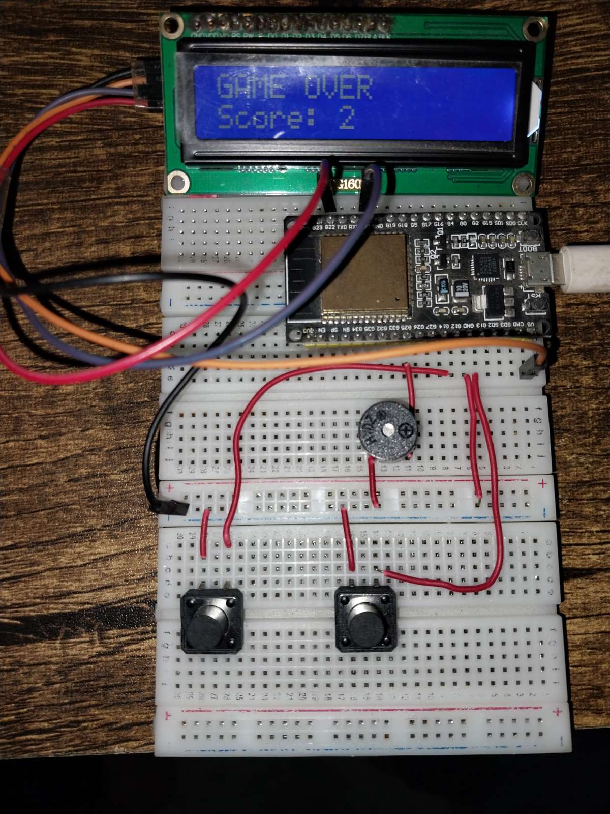
Step 13: Game Over Screen
When:
lives == 0
The display shows:
GAME OVER
Score: XX
The buzzer plays a low tone and waits for the player to press any button to restart.
Step 14: Main Program Loop
The game continuously repeats:
Step 15: Upload the Code
- Open Arduino IDE.
- Install the LiquidCrystal_I2C library.
- Select your ESP32 board.
- Select the COM port.
- Upload the sketch.
- Press reset.
Your game is ready!
Step 16: Features
- Uses both LCD rows as independent lanes
- Random photon spawning
- Smooth movement using custom characters
- Dynamic speed increase
- Score counter
- Three lives system
- Sound effects with buzzer
- Game Over screen
- Automatic restart
- Non-blocking code using millis()
Step 17: Future Improvements
- Double Photon Mode
- Spawn photons on both rows simultaneously.
- Combo Multiplier
- Consecutive hits increase score multiplier.
- High Score Memory
- Store highest score using EEPROM.
Power-Ups
- Slow Motion
- Extra Life
- Shield
OLED Version:
- Upgrade to a 128×64 OLED display.
Joystick Control:
- Replace buttons with a joystick.
RGB LEDs:
- Add visual effects for hits and misses.
Conclusion
Photon Dodge transforms a simple 16×2 LCD into a miniature arcade machine. By using both rows as independent lanes, custom characters, sound effects, and adaptive speed control, the game provides surprisingly engaging gameplay while demonstrating important, embedded programming concepts such as state machines, timers, random number generation, and non-blocking animation.
If you enjoyed this project, consider adding EEPROM high-score storage, double-photon mode, or RGB lighting effects to create your own portable LCD arcade console.