
The Story Behind This Project
I still remember those school morning clearly.
The bell rings. Everyone settles down. And then begins the ritual - the teacher opens the register, picks up a pen, and starts calling names one by one.
"Rohan?""Present,sir."Karanpreet?""Present.""Jashanpreet?"Silence.Someone shouts - "Absent,Sir."
This goes on for 10 to 15 minutes every single morning. In a class of 40 students, that is nearly 15 minutes of teaching time gone — every day — just to mark who showed up. Multiply that by 200 school days a year and you have lost 50 hours of education to a paper register.
And the problems did not stop at attendance.
When a student needed to leave class early, the teacher would pull out a slip, write it by hand, sign it, and hand it over. No record of it anywhere. No parent notification. The student just walked out, and the parents had no idea until the child got home and said "Yeah, I left early today."
When something broke in the classroom - a fan, a light, a projector - a student would sent out of class to find the maintenance staff. More disruption. More time lost.
When the teacher needed a substitute or wanted to call another staff member, it meant physically walking down to the staffroom or sending a note. In 2026, this felt completely broken.
I thought about all of this and asked myself - what if one small device, mounted on the classroom wall, could handle all of this automatically?
That thought became Smart School System V5
What Is Smart School System V5?
Smart School System V5 is a standlone, wall-mounted touchscreen classroom console built on the ESP32-S3 BOX-3 that automates the five most time-consuming and error-prone tasks in any school classroom:
- Daily student attendance with RFID cards
- Live attendance sync to Google Sheets
- Teacher-verified digital outpass generation with thermal printing
- Instant email alerts for staff, teacher and maintenance calls
- Touchscreen-controller classroom light management via relay module
Everything runs on a single compact device. No laptop, No server, No internet subscription. No technical knowledge required to operate it. Just tap a card, touch a button, and the system does the rest.
The Enclosure Plan (And What Happened)
When I designed this project, I had a full vision in my head - a clean 3D printed enclosure that would house the ESP32 S3 Box 3 RFID module and all the connectionsnearly inside a wall-mounted box Something that looked professional enough to actually be installed in a real classroom.
I even designed the enclosure model. But just before I could print it, my 3D printer broke down. The extruder jammed and the healting element gave out - and repairs took longer than my project deadline allowed.
So the current version demonstrated without the enclosure, with all modules wired openly full visibility of how everything connects. Th system works identically to how it would inside the enclosure - and in fact, showing all the components openly makes it easier to understand the hardware design.
The enclosure remains a planned upgrade, and I have described it in the Future Enhancements sections at the end.
Hardware Components Used
| ESP32-S3 Box 3 | Main brain - touchscreen controller, Wi-Fi, GPIO |
| MFRC522 RFID Module | Reads students and teacher RFID cards via SPI |
| RFID Cards and Key Tags | Unique ID cards assigned to each student and staff |
| 4 Channel Relay Module | Controls 4 classroom lights independently |
| QR204 Thermal Printer | Prints outpass slips and attendance reports |
| Jumper Wires (Male-Female) | Connects all modules to the ESP32-S3 GPIO pins |
| USB C Power supply (5V 2A) | Powers the ESP32 S3 BOX 3 |
| External 5v Supply | Powers the relay module and thermal printer |
Understanding the ESP32-S3 Box 3
The ESP32-S3 Box 3 is not just a microcontroller - it is a complete development kit from Espressif that comes with a built-in 2.4 inch color touchscreen, built-in2.4GHz Wi-Fi, a built in microphone, and an exposed GPIO header that lets you connect external GPIO header that lets you connect external modules without any custom PCB.
For this project, the BOX-3 was the perfect choice because:
- The built-in touchscreen eliminates the need for an external display and touch controller
- The built in WI-Fi handles Google Sheets sync and email sending without any extra module
- The GPIO header directly accepts jumper wires for RFID, relay, and printer connections
- It runs on USB-C power and can be mounted anywhere
- The LovgyanGFX library provides excellent graphics performance on its display
The ESP32-S3 chip inside runs at 240 MHz with dual Xtensa LX7 cores - far more processing power than this project needs, which means the system is always responsive, never lags, and handles all tasks simultaneously with ease
System Architecture - How Everything Connects
Before diving into individual wiring steps, here is the big pictures of how all components interact:
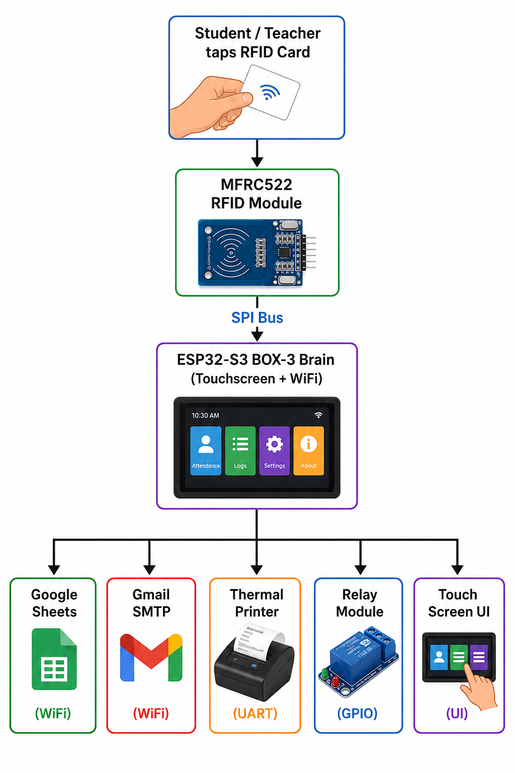
The ESP32 S3 BOX 3 is the central processor. it reads RFID cards, responds to screen touches, and simultaneously triggers cloud updates email alerts, thermal printing, and relay switching - all in the real time.
Step1 - Wiring the MFRC522 RFID Module
The MFRC522 module reads the unique UID from the RFID cards an key tags. It communicates with the ESP32 S3 using the SPI protocol over the FSPI bus.
Connects the MFRC522 to the ESP32-S3 Box 3 as follows
| SDA | GPIO 10 |
| SCK | GPIO 12 |
| MISO | GPIO 13 |
| RST | GPIO 14 |
| MOSI | GPIO 11 |
| GND | GND |
| 3.3v | 3.3v |
Critical: Always use 3.3v for the MFRC522. Connecting it to 5V will permanently damage the module.
Once wired, the MFRC522 is initialized in code using the FSPI bus with the custom pin assignment:
#define SS_PIN    10
#define SCK_PIN   12
#define MISO_PIN  13
#define MOSI_PIN  11

SPIClass RFID_SPI(FSPI);
RFID_SPI.begin(SCK_PIN, MISO_PIN, MOSI_PIN, SS_PIN);
mfrc522.PCD_Init();
Step 2: Wiring the 4-Channel Relay Module
The relay module controls 4 classroom lights or electrical loads indipendently. Each relay is driven by one GPIO out pin on the ESP32-S3
| Relay Channel | ESP32- S3 GPIO | Classroom Load |
| IN1 | GPIO 40 | Light 1 |
| IN2 | GPIO 41 | Light 2 |
| IN3 | GPIO 39 | Light 3 |
| IN4 | GPIO 38 | Light 4 |
| VCC | External 5v | Power |
| GND | GND | Ground |
Critical: Power the relay module from an external 5V supply, not from the ESP32-S3 pins. Relay modules draw more current than the ESP32 GPIO can safely supply.
In code, the relay pins are configured as outputs and start in the LOW (OFF) state:
#define RELAY1 40
#define RELAY2 41
#define RELAY3 39
#define RELAY4 38
pinMode(RELAY1, OUTPUT);
pinMode(RELAY2, OUTPUT);
pinMode(RELAY3, OUTPUT);
pinMode(RELAY4, OUTPUT);
digitalWrite(RELAY1, LOW);
digitalWrite(RELAY2, LOW);
digitalWrite(RELAY3, LOW);
digitalWrite(RELAY4, LOW);
When a teacher taps a light button on the touchscreen, the corresponding relay state toggles and the GPIO pin is updated instantly
relayState[0] = !relayState[0];
digitalWrite(RELAY1, relayState[0]);
Step3 - Wiring the QR204 Thermal Printer
The QR204 thermal printer uses UART serial communication. It connects to the ESP32 S3 Hardware Serial1 port using just 2 data wires - TX and RX
| QR204 Printer Pin | ESP32 S3 Box 3 Pin |
| RX | GPIO 43 |
| TX | GPIO 44 |
| GND | GND |
| VCC | External 5v 2A |
Critical: Note that the ESP32 TX connects to the Printer RX and ESP32 RX connects to the Printer TX. Swapping these is the most common mistake and will result in the printer not responding.
The printer uses the ESC/POS command protocol. In code it is initialized as
#define RXD2 44
#define TXD2 43
HardwareSerial PrinterSerial(1);
PrinterSerial.begin(9600, SERIAL_8N1, RXD2, TXD2);
Before every print job, the printer is reset with an ESC POS init command:
uint8_t init_cmd[] = {0x1B, 0x40};
PrinterSerial.write(init_cmd, sizeof(init_cmd));
Step4 - Complete Wiring Summary
here is every connection in the entire system at a glance:
External 5V supply powers the Relay Module VCC and Thermal Printer VCC separately
Step 5 - Setting Up Google Apps Script for Live Cloud Sync
Every time a student scans their RFID card, the attendance entry is instantly pushed to a Google Sheet. This is instantly through a Google Apps Script web endpoint - completely free, no server required.
5.1 Create the Google Sheet
- Go to sheets.google.com and create a new spreadsheet
- Name it: Attendance
- In Row1, add these headers: Name | UID | Status | Timestamp
5.2 Write the Apps Script
- In your Google Sheet, click Extensions > App Script
- Delete all default code
- Paste the following:
function doGet(e)
{
  var sheet = SpreadsheetApp.openById(
    "paste sheet id here"
  ).getSheetByName("Attendance");

  var name = e.parameter.name;
  var uid = e.parameter.uid;
  var status = e.parameter.status;

  var date = Utilities.formatDate(
    new Date(),
    Session.getScriptTimeZone(),
    "dd-MM-yyyy"
  );

  var time = Utilities.formatDate(
    new Date(),
    Session.getScriptTimeZone(),
    "hh:mm:ss a"
  );

  sheet.appendRow([
    name,
    uid,
    status,
    date,
    time
  ]);

  return ContentService.createTextOutput(
    "SUCCESS"
  );
}
5.3 Deploy as Web App
- Click Deploy > New Deployement
- Type: Web App
- Execute as: Me
- Who has access: Anyone
- Click Deply
- Copy the long Web App URL that appears
5.4 - Add the URL to Your Code
Open your Arduino sketch and replace the URL value:
String GOOGLE_SCRIPT_URL =
 "https://script.google.com/macros/s/YOUR_SCRIPT_ID/exec";
Now every attendance update, outpass status change, and OPG marking from the ESP32 will append a row to your Google Sheet on real time over Wi-Fi using this simple GET request:
String url = GOOGLE_SCRIPT_URL +
 "?name=" + name +
 "&uid=" + uid +
 "&status=" + status;
http.begin(url);
http.setFollowRedirects(HTTPC_STRICT_FOLLOW_REDIRECTS);
http.GET();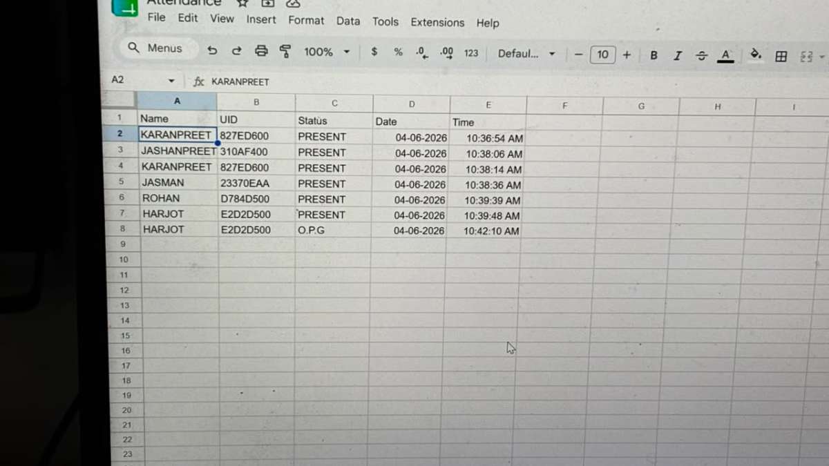
Step6: Setting Up Gmail Email Notifications
The system sends email alerts for staff calls, teacher calls, maintenance call, and parent outpass notifications using Gmail SMTP via the ESP_Mail_Client library.
6.1 Enable 2-Step Verification
- Go to myaccount.google.com > Security
- Enable 2-Step Verification
6.2 Generate an App Password
- Go to myaccount.google.com > Security > App Passwords
- App: Mail | Device: Other (name it ESP32)
- Click Generate
- Copy the 16-character password shown
6.3 Update the Code
#define SMTP_HOST "smtp.gmail.com"
#define SMTP_PORT 465
#define AUTHOR_EMAIL    "[email protected]"
#define AUTHOR_PASSWORD "your_app_password_here"
#define RECIPIENT_EMAIL "[email protected]"
Note: AUTHOR_PASSWORD must be the App Password you just generated - NOT your regular Gmail password.
6.4 How Email Is Sent
The sendEmail() function handles all email sending. It establishes an SSL connection to GMail SMTP, authenticates using the app password, and sends the message:
void sendEmail(String subject, String body, String receiver) {
 Session_Config config;
 config.server.host_name = SMTP_HOST;
 config.server.port      = SMTP_PORT;
 config.login.email      = AUTHOR_EMAIL;
 config.login.password   = AUTHOR_PASSWORD;
 SMTP_Message message;
 message.sender.name  = "XYZ PUBLIC SCHOOL";
 message.sender.email = AUTHOR_EMAIL;
 message.subject      = subject;
 message.addRecipient("Receiver", receiver);
 message.text.content = body.c_str();
 smtp.connect(&config);
 MailClient.sendMail(&smtp, &message);
}
This same functions is reused for all four alert types - staff, teacher, maintainer, and parent outpass notification.
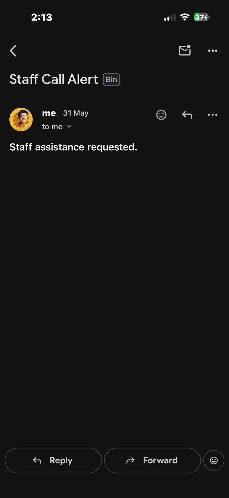
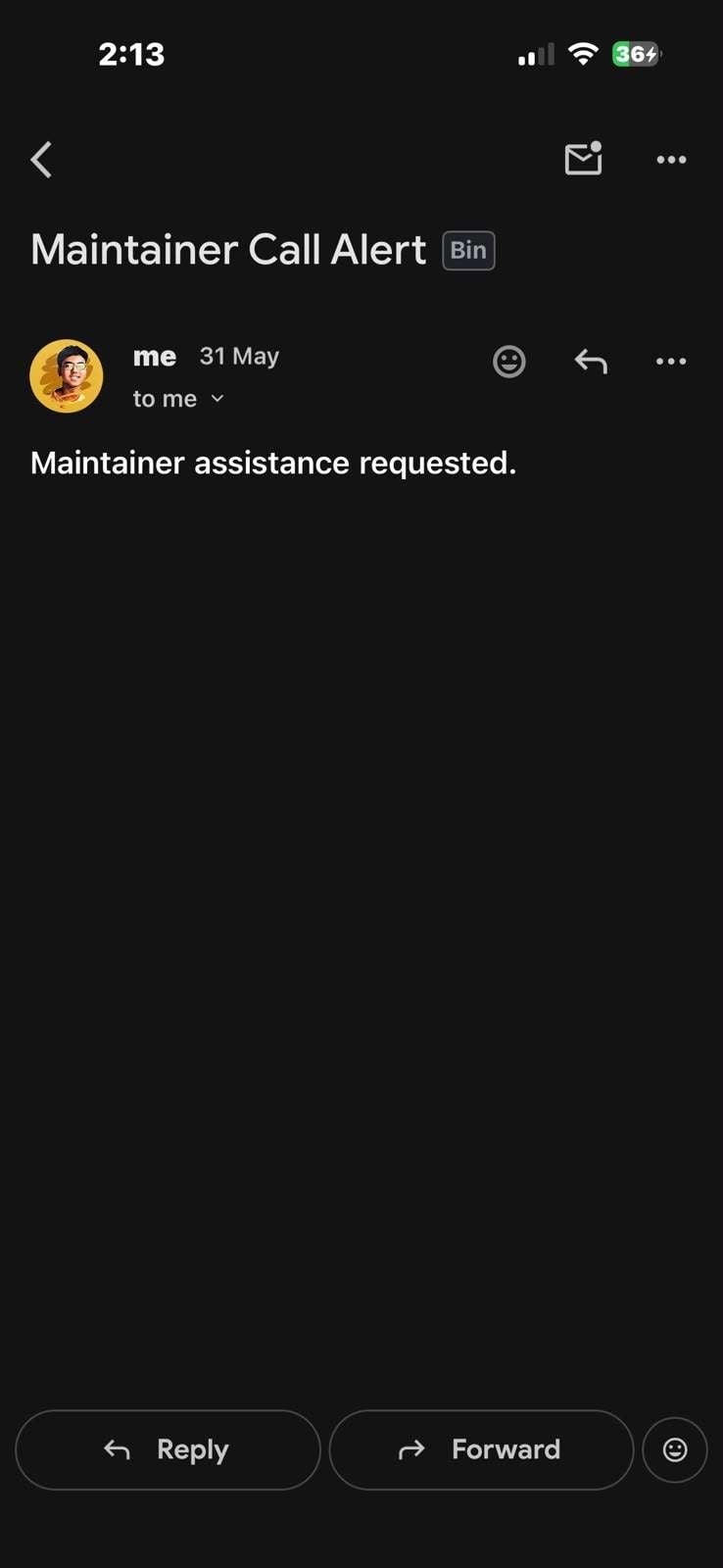
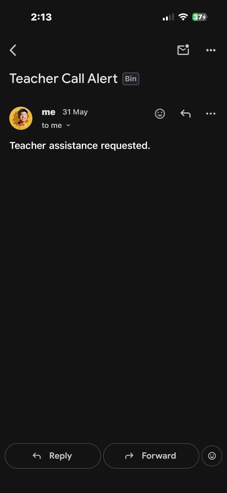
Here are the screen shots of staff call, teacher call, parent outpass notifications
Step 7 - Installing Libraries and Uploading Code
7.1 Install Arduino IDE
Download and install Arduino IDE 2.x from arduino.cc
7.2 Add ESP32 Board Support
- Go to FIle > Preferences
- In Addtional Board Manager URLs, add:
https://raw.githubusercontent.com/espressif/arduino-esp32/gh-pages/package_esp32_index.json- Go to Tools > Board > Board Manager
- Search: esp32
- Install: esp32 by Espressif Systems
7.3 Install Required Libraries
Go to Tools > Manage Libraries and install each of these:
- LovgyanGFX - Display graphics for ESP32 S3 Box 3
- MFRC522v2 - RFID card reading
- ESP Mail Client - Gmail SMTP email sending
7.4 Board Configuration
- Tools > Board > ESP32 S3 Dev Module
- Tools > Port > Select your COM port
- Tools > USB CDC On Boot > Enabled
- Tools > Flash Size > 16MB (for ESP32 S3 Box3)
7.5 Upload
- Open the project .ino file
- Click the Upload button (right arrow)
- Wait for "Done uploading" in the output console
Step 8 - First Boot
Once uploaded, disconnect and reconnect USB-C power. The system boots automatically:
- Screen displays:"CONNECTING Wi-Fi...." while it joins your network
- Boot animation plays - "SMART SCHOOL SYSTEM V5" in cyan text on black screen for 2 seconds
- Home screen loads - "SCAN RFID CARD" with the live date and time at the top
The NTP time sync runs during setup:
const char* ntpServer    = "pool.ntp.org";
const long  gmtOffset_sec = 19800;  // IST = UTC + 5:30
configTime(gmtOffset_sec, 0, ntpServer);
IST offset is 5 hours 30 minutes = 19800 seconds. The clock updates every second on every screen so the time is always accurate.
How the System Works - Screen by Screen
The entire UI is built around 5 screens navigated using two arrow buttons (< and >) at the top of every screen. A live clock at the top shows the current date and time on all screens at all times
Screen 1 - RFID Attendance (Home Screen)
.jpeg)
This is the screen the device always starts on and always returns to .
The display shows: "SCAN RFID CARD" with a subtitle "Tap Card To Mark Attendance"
When a student taps their RFID card:
- The MFRC522 reads the card UID in under 50 milliseconds
- The system looks up the UID in the local user database
- If the student is ABSENT, their status flips to PRESENT
- A welcome screen show their Name, Class, Section, Roll No., and Status for 3 seconds
- The system sends the attendance update to Google Sheets over Wi-Fi in the background
- The screen returns to the RFID home screen, ready for the next student
Attendance Lock after 1 PM:
The system automatically checks the current time on every card scan . If the time is 1:00 PM or later, attendance is closed Any card tap shows:
ATTENDANCE CLOSED
...and returns to the home screen after 3 seconds. This prevents students from marking attendance late or manipulating the register after school hours.
bool attendanceOpen() {
 struct tm timeinfo;
 if (!getLocalTime(&timeinfo)) return true;
 if (timeinfo.tm_hour >= 13) return false;
 return true;
}
Screen 2 - Light Control Panel
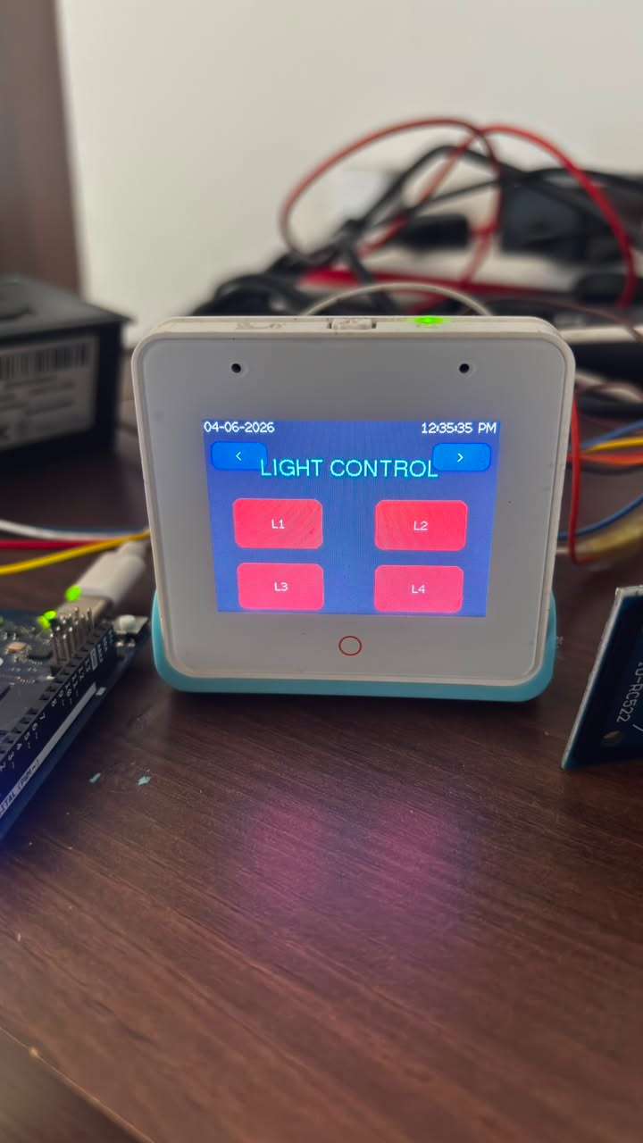
Tap the > arrow once from home to reach the Light Control Screen.
Four large rounded buttons appear on the touch screen - L1, L2, L3, L4 - each representing one classroom light or electrical load connected to the relay module.
- Tap once: Button turns GREEN, relay closes, light turns ON
- Tap again: Button turns RED, relay opens, light turns OFF
The button color reflects the real physical state of the relay at all times. This screen lets the teacher control all classroom lights without touching a single physical switch.
Screen 3 - Attendance Status Board
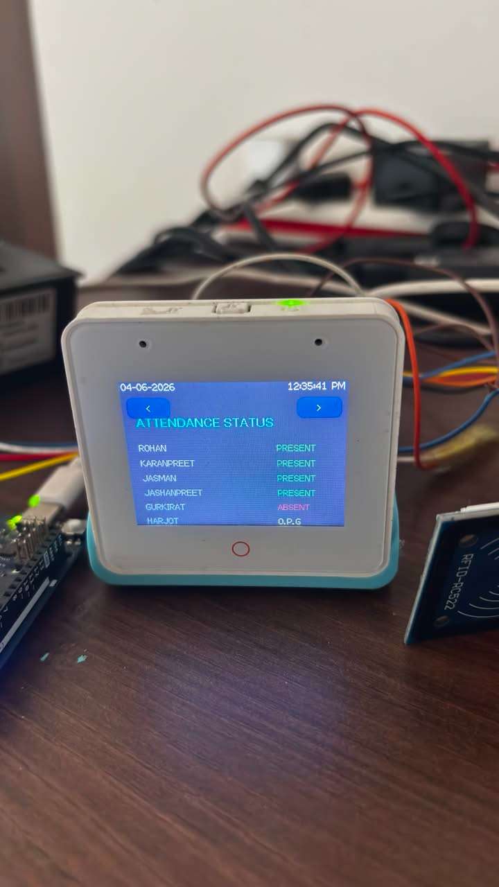
Tap > once more to see the live attendance dashboard.
Every student in the class is listed with their current status shown in color:
- GREEN text = PRESENT
- RED text = ABSENT
- YELLOW text = OPG (Out Pass Generated)
This screen gives the teacher an instant visual summary of who is present who is absent, and who left on an outpass - without opening any register or app.
Screen 4 - Call Services and Outpass Generator
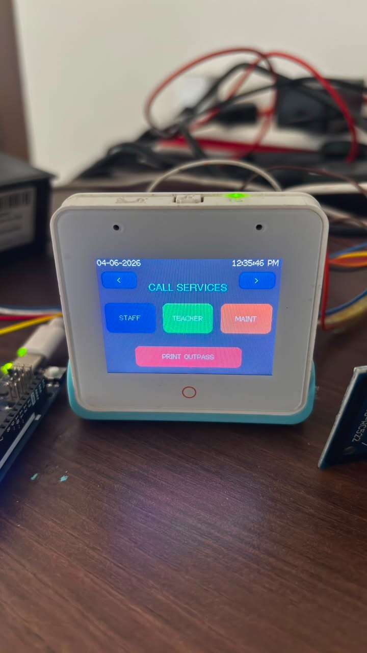
Tap>one more time to reach the most feature-rich screen in the system.
Three call buttons:
- STAFF (Blue): Sends an email to the school staff: "Staff assistance requested from classroom."
- TEACHER (Green): Sends an email to another teacher: "Teacher assistance requested from classroom."
- MAINT (Orange): Sends an email to maintenance: "Maintenance assistance requested from classroom."
One tap sends the email. The screen briefly shows "STAFF EMAIL SENT" (or teacher/maintainer) as confirmation, then returns to the call screen. No phone call needed. No student needs to leave the classroom.
Outpass Generation (Full Flow):
This is the most carefully designed feature of the system. Generating an outpass requires two RFID scans - student first, then teacher - making it impossible for a student to generate theor own outpass.
Step-by-Step Flow:
- Teacher taps PRINT OUTPASS button
- Screen changes to: "SCAN Student RFID"
- Student taps their card - their Name, Class, Section, Roll No. appear on screen
- Teacher reviews the details - two options: AGAIN (re-scan) or CONFIRM
- Teacher taps CONFIRM - screen shows: "SCAN TEACHER RFID"
- Teacher taps their own RFID card
- System verifies the card is a TEACHER role card
- If valid:
- Student status updates to OPG in local database
- Google Sheet is updated student name, UID, OPG, timestamp
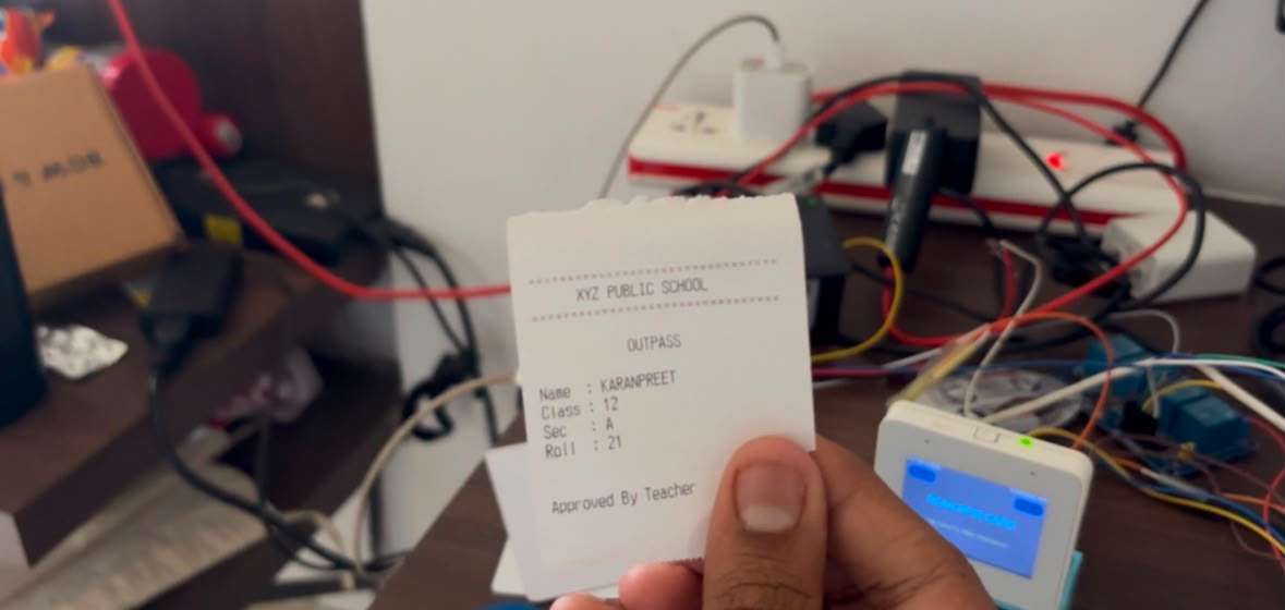
- Thermal printer outputs the physical outpass slip
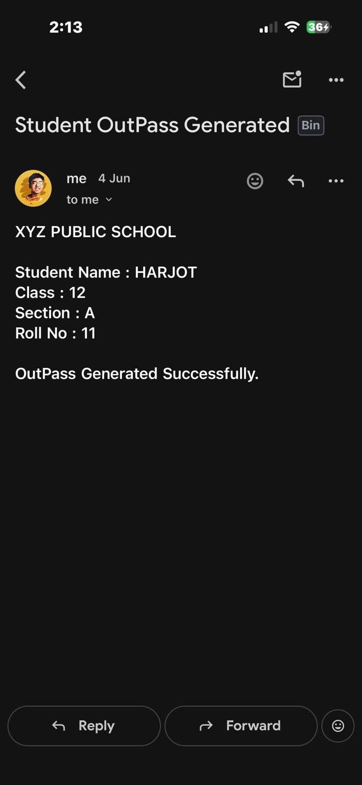
- Email sent to parent's registered email with student details and outpass confirmation
9. Screen returns to home after 3 seconds
If an invalid card is scanned at the teacher verify step, the screen shows "INVALID TEACHER" and returns - blocking the oupass completely
Sample Outpass Slip
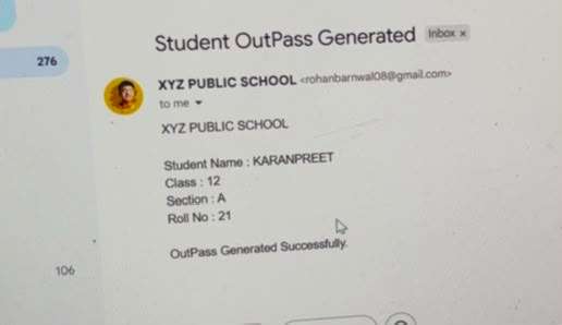
Outpass Mail To Parents
Screen 5 - Attendance Report Print
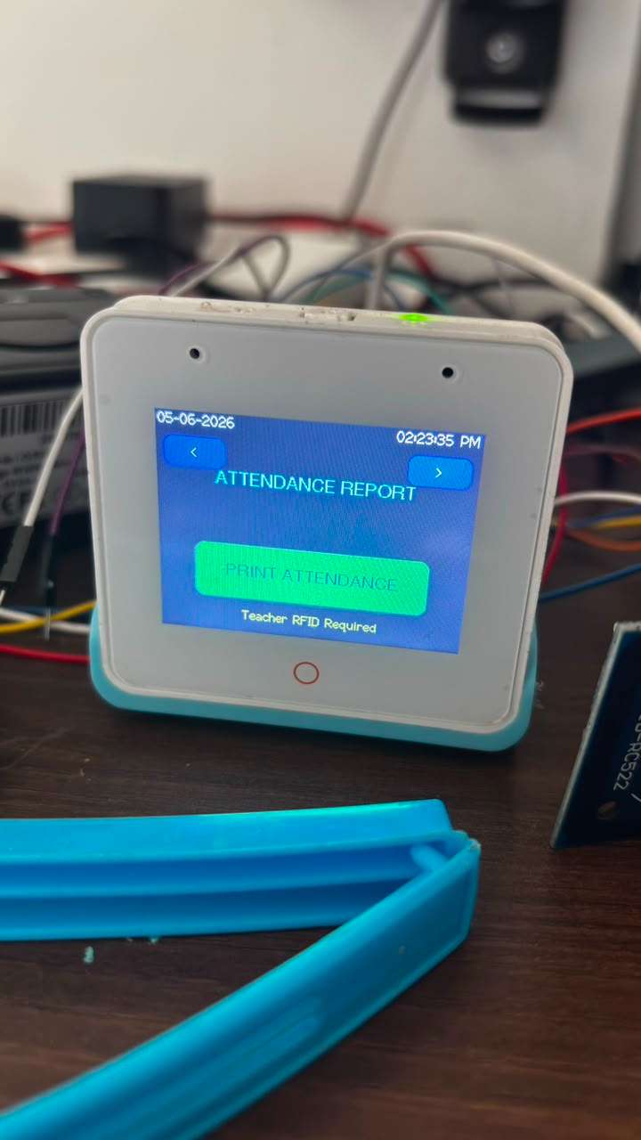
Tap > from Screen 4 to reach the Attendance Report screen.
This screen has one button: Print Attendance
when tapped, the system requires Teacher RFID verification before printing - same security as outpass generation. This ensures only the teacher can print the official attendance record.
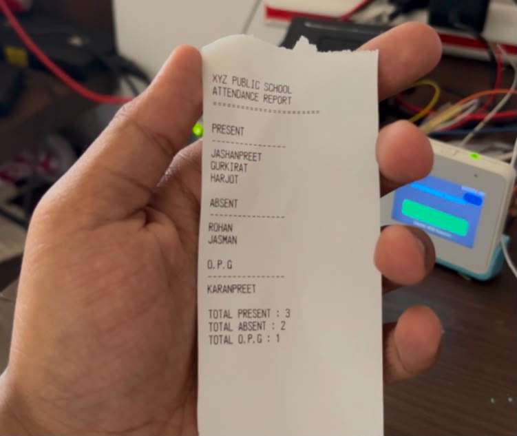
On successful teacher scan, the thermal printer outputs the complete attendance report:
The printed report serves as the official daily attendance record that the teacher submits to the school office - fully replacing the handwritten register
How the User Database Works
The student and staff database lives directly in the ESP32 flash memory as a C++ array of User structs. Each user has a UID (read from their RFID card), name, role, class, section, roll number, current status, and parent email:
struct User {
 String uid;
 String name;
 String role;
 String className;
 String section;
 int    rollNo;
 String status;
 String parentEmail;
};
User users[] = {
 { "2A7E17B1", "TEACHER",     "TEACHER",  "", "", 0,  "", "" },
 { "7EB6F300", "STAFF",       "STAFF",    "", "", 0,  "", "" },
 { "5C55D500", "MAINTAINER",  "MAINTAINER","","", 0,  "", "" },
 { "D784D500", "ROHAN",       "STUDENT",  "12","A",12,"ABSENT","[email protected]" },
 { "827ED600", "KARANPREET",  "STUDENT",  "12","A",21,"ABSENT","[email protected]" },
 // ... more students
};
When any card is scanned, the system loops thorugh this array, matches the UID, and responds based on the role - STUDENT gets attendance marked, TEACHER unlocks outpass and report printing.
To add a new student, add a new entry to this array with their card UID and details, than re-upload the code.
Security Design
The system has multiple layers of access control built in:
- Attendance Lock After 1 PM - The NTP-synced clock enforces an automatic cutoff. No student can mark present after 1 PM regardless of how many times they tap their card.
- Double RFID Verification for Report Print: The attendance report can only be printed after a valid teacher card is scanned . Students cannot access attendance data.
- Status Lock on Outpass: Once a student is marked OPG their status cant be changed back to ABSENT ot PRESENT automatically. It is a permanent record for that day
Real-World Impact
For the Teacher: Attendance that used to take 12-15 minutes now takes 2-3 minutes. The teacher taps the attendance screen, students scan as they enter, and the register is done before the bell even stops ringing.
For the school administration: The Google Sheets dashboard gives the principal, vice principal, or attendance clerk a live view of every classroom's attendance from any device — phone, tablet, laptop — without waiting for physical registers to be collected and tallied.
For Parents: When their child gets an outpass, they receive an email within seconds. No more finding out at the end of the day. No more surprise early departures.
For the Maintenance Staff: They receive an email the moment a classroom reports a problem. No student needs to leave class, no teacher needs to walk to the staffroom. Faster response, less disruption.
For the school: A single device per classroom replaces:
- The daily attendance register
- The outpass slip book
- The classroom light switch panel
- The staff/teacher intercom
- The parent notification phone call
Scalability and Deployment
Adding more students: Add entries to the users[] array with each student's RFID card UID and details. The system supports as many students as the ESP32 flash memory can hold — easily hundreds per classroom.
Deploying in multiple classrooms: Each classroom gets one BOX-3 unit. The Google Script URL can point to a shared school spreadsheet with multiple sheets — one per classroom. Each device sends data to its own sheet tab.
Different email recipients: Each device can have different AUTHOR_EMAIL and RECIPIENT_EMAIL values. Classroom 1 emails one teacher, Classroom 2 emails another.
Future integration: The Google Sheets database can feed into monthly attendance summary reports, automated absentee alerts, annual attendance percentage calculations, and CSV exports for the school management system — all without touching the ESP32 at all.
Future Enhancements
3D Printed Wall Enclosure As mentioned earlier, a custom enclosure was designed for this project. The plan is a wall-mountable box that houses the ESP32-S3 BOX-3, RFID module, and cable management in a clean, professional form factor that looks like it belongs in a school classroom. The 3D printer repair is underway and this will be the first upgrade once it is operational.
WhatsApp Notifications Instead of only email, outpass and attendance alerts can be sent via WhatsApp using the Twilio API or WhatsApp Business API — reaching parents on the platform they actually check.
BLE-Based RFID Card Enrollment Currently, adding a new student requires editing the code and re-uploading. A future version will include a card enrollment screen on the device itself — tap an unregistered card, enter student details via a soft keyboard on the touchscreen, and the card is registered instantly without touching a computer.
Daily Summary Email to Principal At the end of every school day, the system can automatically send a summary email to the principal with total present/absent/outpass counts across all classrooms.
Biometric Backup An R307 or AS608 fingerprint sensor can be added alongside the RFID module as a backup identification method for students who forget or lose their cards.
Classroom Nameplate Display A small OLED display mounted outside the classroom door can show the current period, subject, and teacher name — updated automatically by the same ESP32 device inside.
Automatic Light Scheduling Instead of manual relay control, the relay module can be programmed with a schedule — lights turn on at 8 AM, off at 1 PM for lunch, on again at 1:30 PM, off at 5 PM — automatically, without any teacher interaction.
Video Demonstration
Conclusion
Smart School System V5 started as a frustration — years of watching time, effort, and accuracy get lost to manual classroom processes that have not changed in decades.
It became a hardware project that proves how much a single well-designed embedded device can do. One ESP32-S3 BOX-3, four modules, a roll of thermal paper, and a set of RFID cards — and an entire classroom runs itself.
Attendance is automatic. Outpasses are verified and tracked. Parents are notified instantly. Lights are controlled from the teacher's fingertip. The administration has live data on a screen. And the teacher gets back the 15 minutes every morning that used to be lost to a paper register.
This is not a concept or a simulation. Every feature in this project is built, tested, and working. The RFID scans. The printer prints. The emails send. The Google Sheet updates. The relays click.
One tap. Every classroom. Every school.