SmartDock – Universal Adaptive Charging Dock for Wireless Earbuds
[WITH ATTACHED WORKING VIDEO]
Circuit working video;
Introduction
Wireless earbuds have become an essential part of daily life. However, one common problem faced by users is the loss or damage of the original charging case. Since most earbuds depend on proprietary charging cases, replacing them is often expensive or sometimes impossible. This inspired the development of SmartDock, a universal adaptive charging dock capable of accommodating different earbud designs while also monitoring their charging status.
The objective of this project was not only to provide a charging solution but also to develop a system that can estimate the charging state of an earbud using charging-current measurements.
Step 1: Understanding the Charging Behaviour of Earbuds
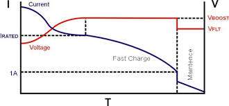
The first stage of the project involved studying how lithium-ion batteries inside wireless earbuds charge. During charging, the battery current gradually decreases as the battery approaches full charge.
This observation led to the idea of estimating the battery charge level by monitoring charging current instead of directly accessing the battery.
Step 2: Designing a Universal Earbud Interface
A major challenge was creating a charging interface that could work with earbuds from different manufacturers.
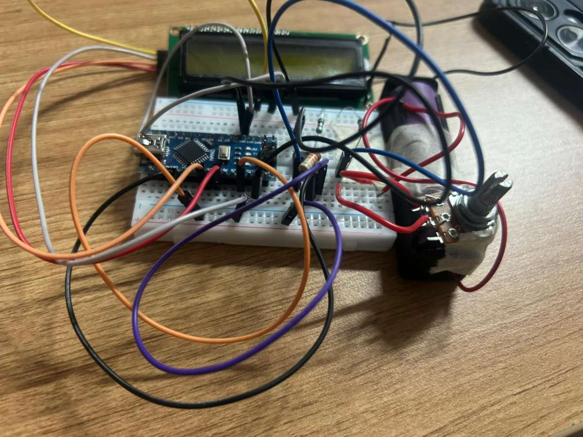
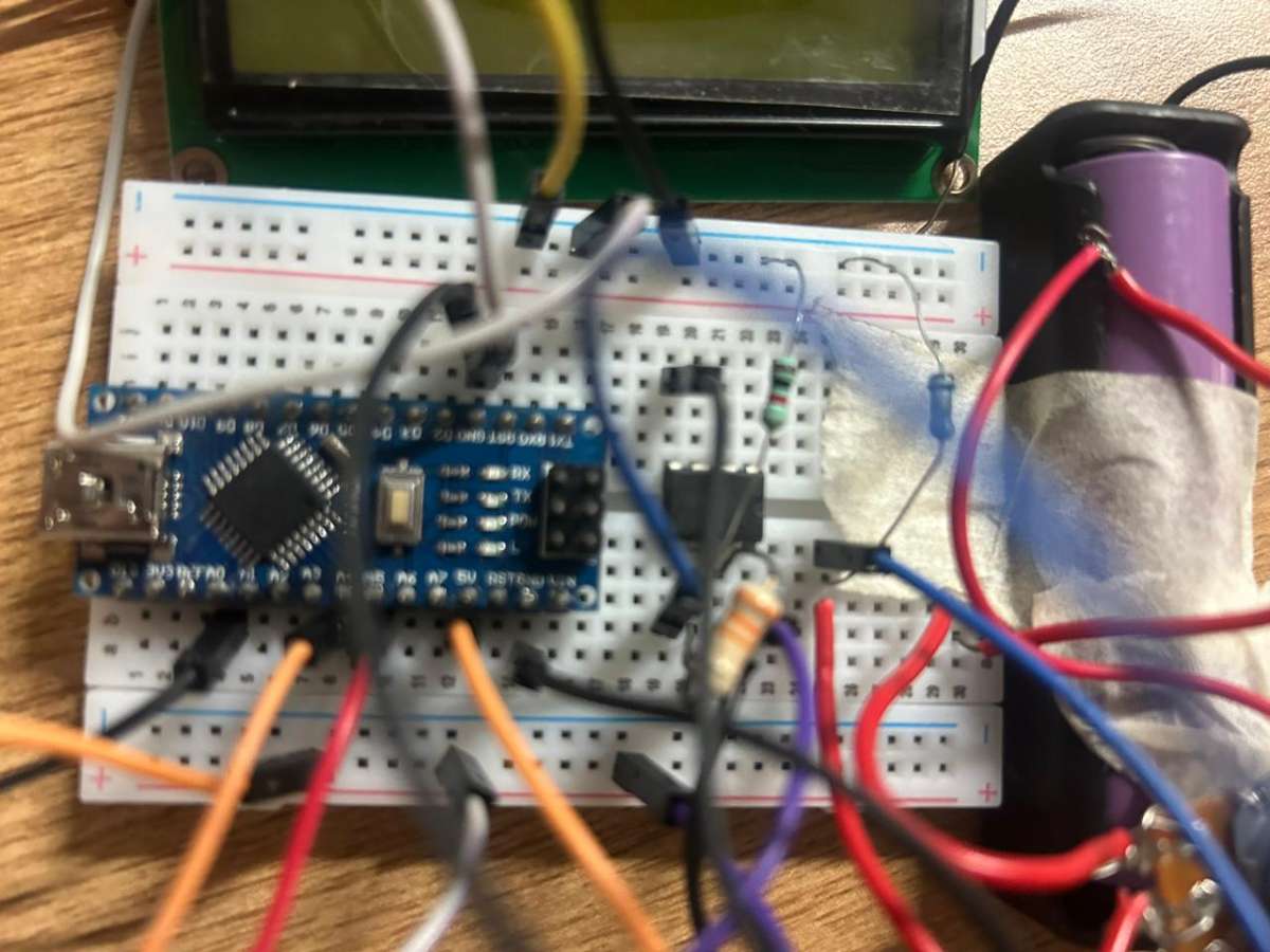
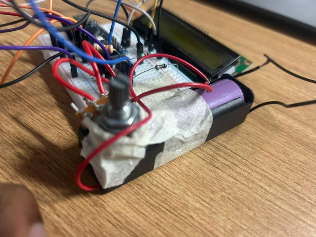
To address this, a flexible silicone-supported holder was proposed. The silicone structure is designed to adapt to different earbud shapes while spring-loaded gold-plated contacts provide reliable electrical connectivity to the earbud charging terminals.
This allows the same dock to support multiple earbud models without requiring a dedicated charging case.
.png)
.png)
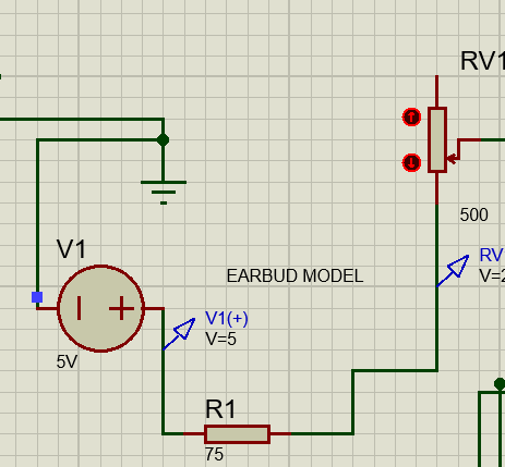
Step 3: Developing an Earbud Electrical Model
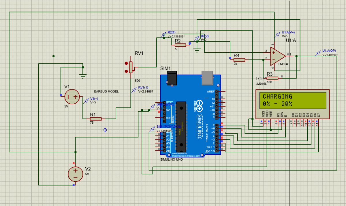
Since different earbuds draw different charging currents, an equivalent electrical model was developed in Proteus to emulate earbud charging behaviour.
Several approaches were initially explored, including current-controlled current sources and piecewise current-source models. However, these methods produced unstable or unrealistic simulation results.
A simpler and more reliable Thevenin-equivalent earbud model was finally adopted. The model uses a fixed source and variable resistance to emulate different charging-current conditions.
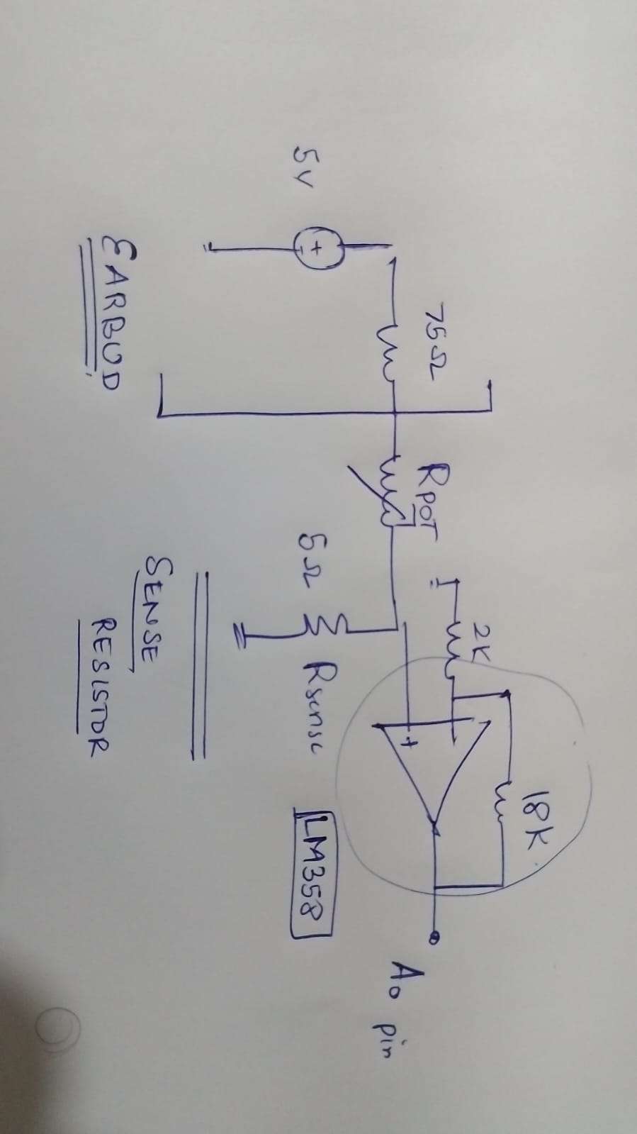
Step 4: Current Sensing
To estimate charging status, charging current must first be measured.
A low-value sense resistor was placed in the charging path. As charging current flows through the resistor, a small voltage proportional to current is developed across it.
Because this voltage is very small, it cannot be directly processed accurately by the Arduino.
Step 5: Signal Conditioning Using LM358
The sensed voltage is amplified using an LM358 operational amplifier configured as a signal-conditioning stage.
This stage increases the measurable voltage range while maintaining proportionality to charging current.
The conditioned signal is then fed to the Arduino analog input, allowing accurate monitoring of different charging states.
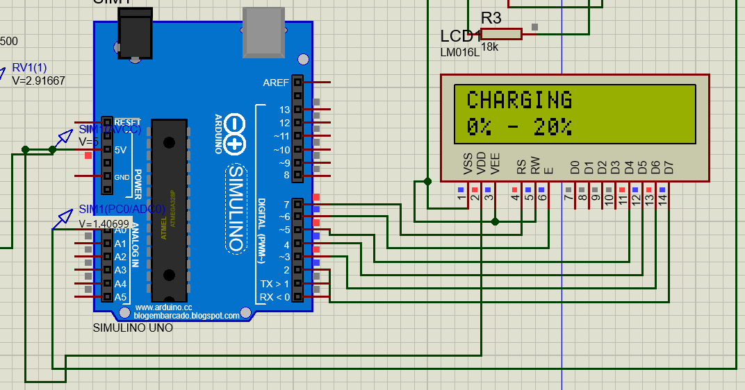
Step 6: Arduino-Based Charge Estimation
The Arduino continuously reads the amplified voltage signal through its ADC.
Based on experimentally determined current ranges, the system estimates the approximate battery charge state.
The charging ranges used in this project are:
| Charge Range | Approximate Current |
|---|---|
| 0–20% | Highest charging current [ > 45 mA] |
| 20–40% | High charging current [45-35 mA] |
| 40–60% | Moderate charging current [35-25 mA] |
| 60–80% | Reduced charging current [25-15 mA] |
| 80–95% | Low charging current [15-5 mA] |
| Fully Charged | Very low charging current [ < 0.05 mA] |
Instead of displaying an exact percentage, SmartDock displays practical charging ranges that are easier for users to interpret.
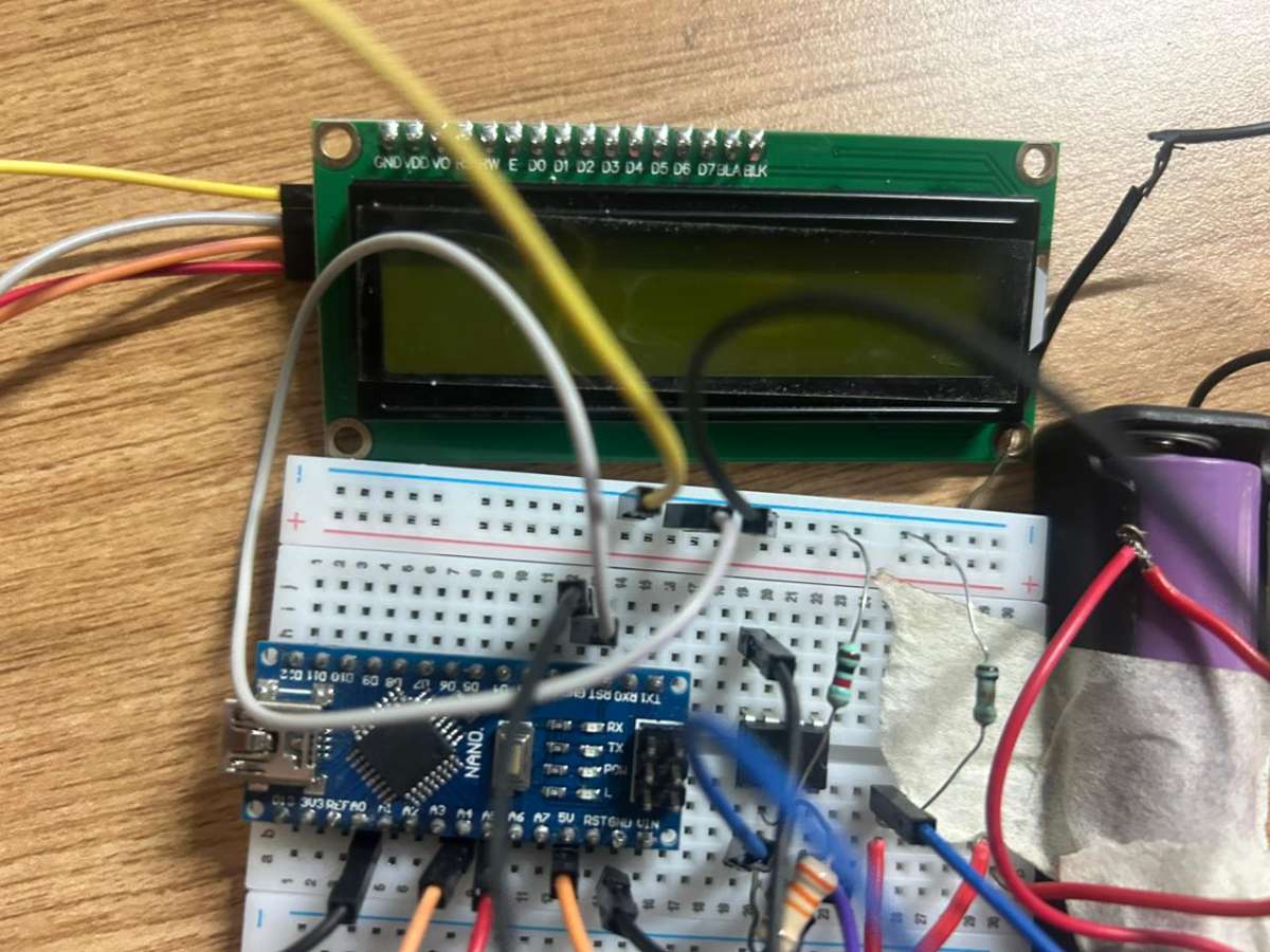
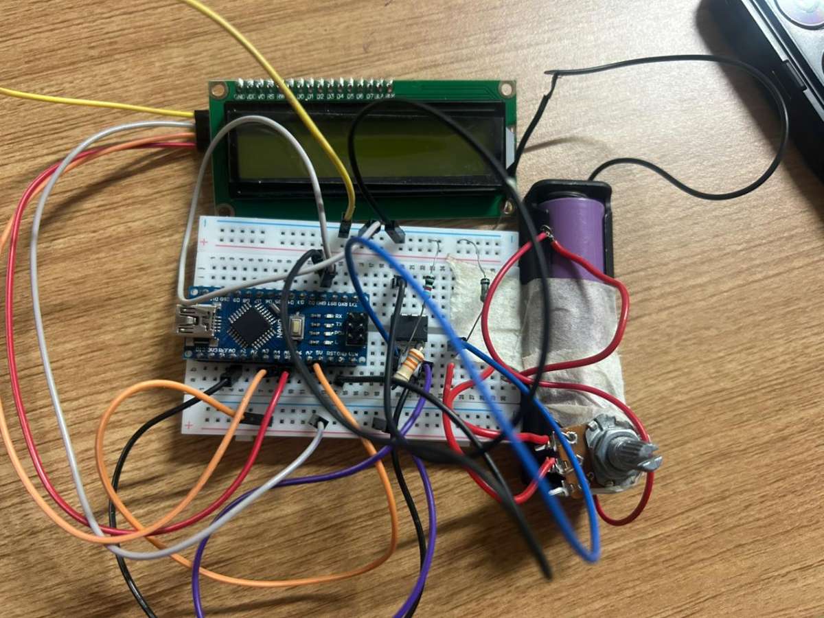
Step 7: LCD Monitoring Interface
A 16×2 LCD was integrated to provide real-time charging information.
At startup, the display shows:
" Earbud Charge Monitor "
During operation, it displays the current charging range such as:
" CHARGING 0% – 20% "
or
" FULLY CHARGED – READY TO USE "
This provides a simple user interface without requiring any mobile application.
Step 8: Simulation and Testing
The complete SmartDock system was simulated and tested in Proteus.
Different charging conditions were generated by varying the equivalent earbud resistance. The Arduino successfully detected the corresponding charging ranges and updated the LCD display accordingly.
Multiple operating points were verified to ensure correct charge-state estimation.
Challenges Faced
Several challenges were encountered during development:
- Modeling realistic earbud charging behaviour.
- Generating stable current variations in simulation.
- Converting very small sense-resistor voltages into usable ADC signals.
- Mapping charging-current values to practical battery-charge ranges.
- Designing a universal earbud holder capable of adapting to different earbud geometries.
These challenges led to multiple design iterations before arriving at the final SmartDock architecture.

Final Outcome
SmartDock demonstrates a practical approach toward universal wireless-earbud charging. By combining adaptive mechanical contacts, current sensing, signal conditioning, and Arduino-based charge estimation, the system provides a low-cost and scalable solution for users who have lost or damaged their original charging cases.
The project successfully demonstrates both the hardware architecture and the charge-monitoring algorithm required for a universal adaptive earbud charging dock.