Github repo.
Industry 4.0 & The Problem
The era of Industry 4.0 revolves around automation, smart manufacturing, and data-driven decision-making. In modern smart factories, unexpected machinery breakdown is one of the most expensive issue, causing massive operational losses and safety hazards.
Traditional maintenance solutions rely heavily on cloud gateways, where raw sensor data is constantly streamed to remote servers. This approach creates severe bottlenecks:
- High Latency: Network delays can slow down critical warning alerts.
- Connectivity Barriers: Many industrial shop floors are radio-shielded or completely lack reliable internet access.
- Prohibitive Costs: Cloud storage subscriptions and bandwidth costs frequently price out small-and-medium enterprises (SMEs).
This project presents a practical solution: a fully autonomous, ultra-low-cost Edge AI predictive maintenance node that runs complex machine learning models directly on a microcontroller—completely offline and local.
"Machine Prototype" Setup
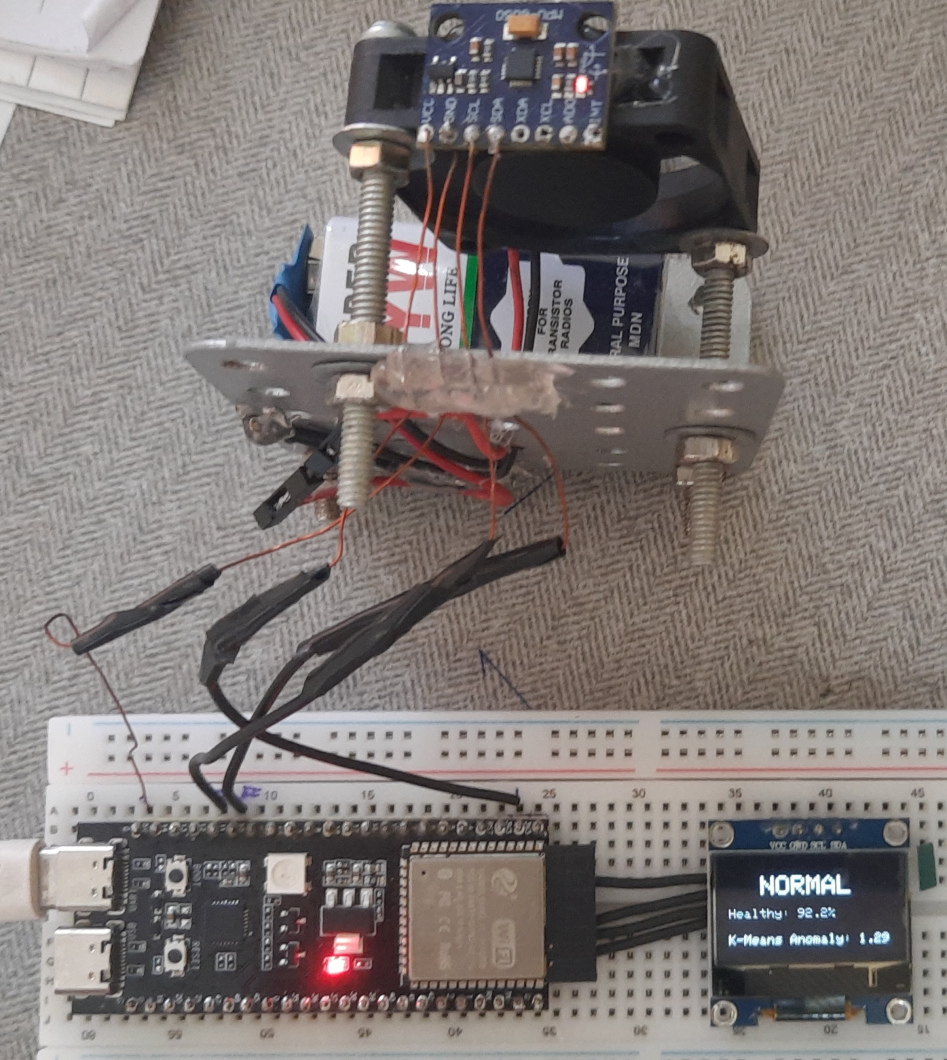
To demonstrate real-world industrial fault conditions, I built a mechanical test rig using a standard 5V DC cooling fan mounted on a rigid aluminium frame (i got the frame for free from my nearest junkyard hehe). An MPU6050 6-DoF Inertial Measurement Unit (IMU) was securely bolted to the fan housing to capture high-frequency physical vibrations along the X, Y, and Z axes.
I simulated two distinct structural states on this apparatus:
- Normal Condition: All four mounting bolts are completely tightened, producing a balanced, low-amplitude, and rhythmic vibration signature.
- Loose Bolt Condition (Fault State): One of the main mounting bolts is deliberately loosened, introducing spatial asymmetry and mechanical micro-impacts against the chassis during operation.
Data Collection via Edge Impulse Data Forwarder
To collect data in order to train the model , I used the Edge Impulse Data Forwarder over a standard USB Serial connection.
A custom data collection firmware was flashed to the ESP32-S3, which sampled the MPU6050 accelerometer axes at a fixed frequency of 100 Hz. The data forwarder streamed these raw values into the Edge Impulse Studio cloud seamlessly. I recorded a total dataset of 6 minutes and 40 seconds of vibration data across both conditions, maintaining a clean 80/20 split between training and testing data sets.
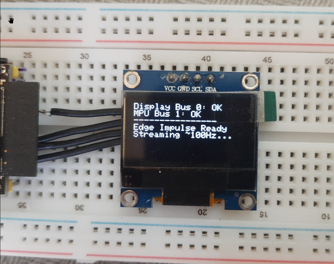
Important I2C System Design Note: During initial development, high-frequency display refreshes on a shared I2C bus caused electrical arbitration conflicts, corrupting sensor timing. To guarantee a precise 100 Hz sampling rate, I divided the peripherals across two independent I2C buses: the SSD1306 OLED screen sits on Wire0 running at 400 kHz (Fast Mode), while the time-critical MPU6050 sensor is isolated on Wire1 running at 100 kHz (Standard Mode) for perfect signal integrity over longer connection lines.
Model Architecture (on Edge-Impulse)
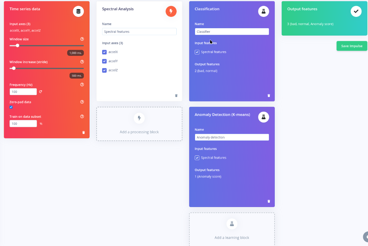
A massive challenge in manufacturing predictive maintenance is that you cannot realistically train an AI for every single failure type. To tackle this, my project deploys a two way approach where a classifier (supervised) model handles known faults, while an k-anomaly (unsupervised) model flags unknown anomalies.
Digital Signal Processing (DSP) Pipeline
Before training, raw time-series inputs pass through a Spectral Analysis block operating on a 1,000 ms sliding window with a 500 ms stride. It performs:
- Fast Fourier Transform (FFT): Extracts frequency domain harmonics to show structural vibration peaks.
- High-Pass Filter: Strips out the constant static gravity offset (9.8g), ensuring the models learn only from dynamic acceleration anomalies rather than the absolute orientation of the device.
Implementation, On-Device Performance & Code
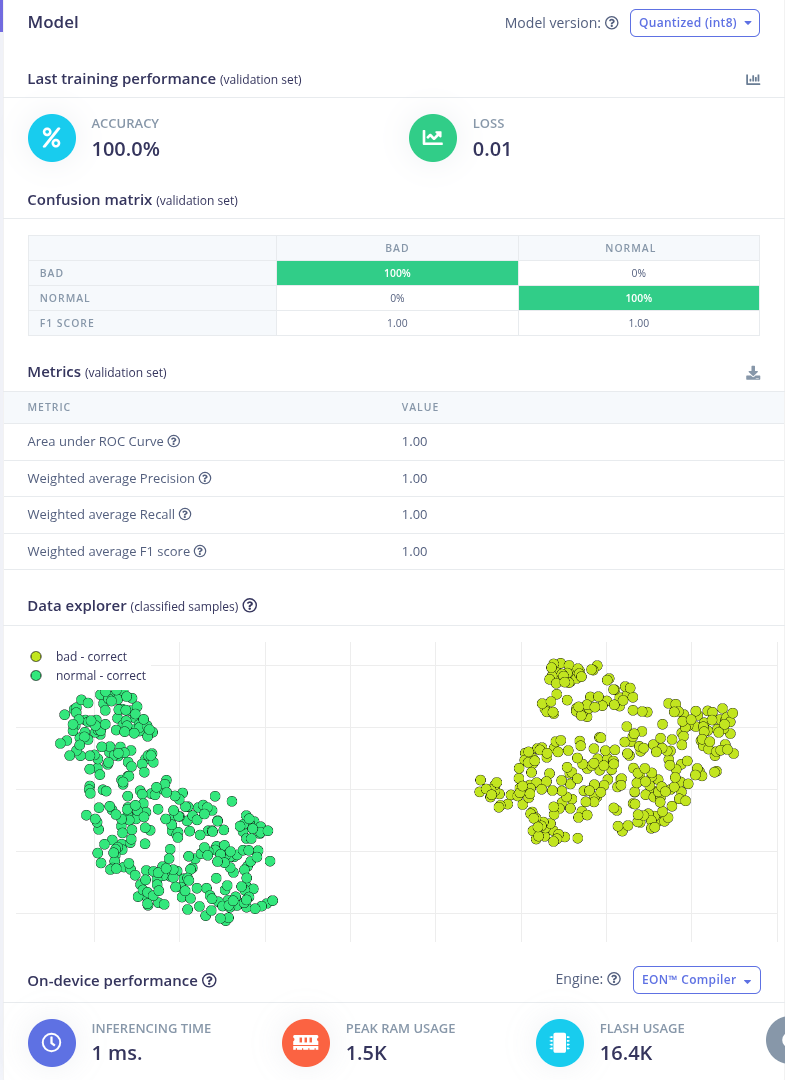
The models were compiled using the Edge Impulse EON™ Compiler, which generates pure, optimized C++ source code instead of relying on a bulky interpreter runtime. This results in highly efficient resource consumption benchmarks on our ESP32-S3:
- Inference Speed: ~1 millisecond for the entire combined DSP + inference calculation!
- Peak RAM Consumption: 1.5 KB
- Flash Footprint: 16.4 KB
This demonstrates that any entry-level microcontroller layout (such as an n8r4) can run this production-grade pipeline easily.
Below is the structured main execution loop deployed in the firmware:
// Collect 1 second of data at exactly 100 Hz
for (size_t ix = 0; ix < EI_CLASSIFIER_DSP_INPUT_FRAME_SIZE; ix += 3) {
uint64_t next_tick = micros() + (1000000 / EI_CLASSIFIER_FREQUENCY);
xyzFloat accel = myMPU.getGValues();
buffer[ix+0] = accel.x;
buffer[ix+1] = accel.y;
buffer[ix+2] = accel.z;
if (next_tick > micros()) {
delayMicroseconds(next_tick - micros());
}
}
// Wrap buffer into an Edge Impulse signal struct
signal_t features_signal;
numpy::signal_from_buffer(buffer, EI_CLASSIFIER_DSP_INPUT_FRAME_SIZE, &features_signal);
// Run the dual-inference pipeline
ei_impulse_result_t result = {0};
run_classifier(&features_signal, &result, false);
// Fault detection logic evaluation
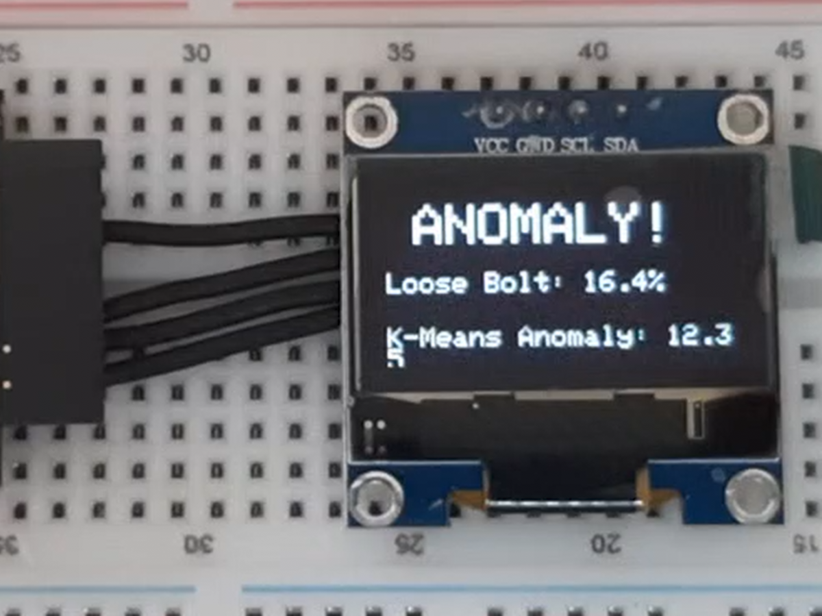
if (result.anomaly > 7.0 || result.classification[0].value > 0.5) {
// Write "ANOMALY!" message and data parameters to the SSD1306 OLED screen
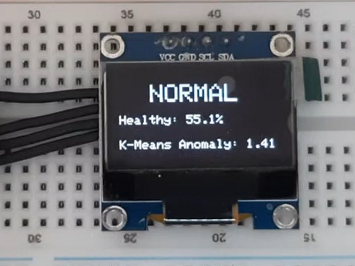
} else {
// Revert screen layout to "NORMAL / Healthy"
}Schematic:
.png)