
AI-Based Smart Parking Detector uses the Arduino Uno R4 WiFi and Seeed's Grove AI Vision Module to detect parking space availability in real time. The vision module performs on-device car detection using edgeAI, eliminating the need for cloud inference. The detected status (occupied or vacant) is sent via WiFi to a web dashboard for live monitoring. This solution helps optimize parking space utilization in smart cities, featuring low power consumption and low latency.

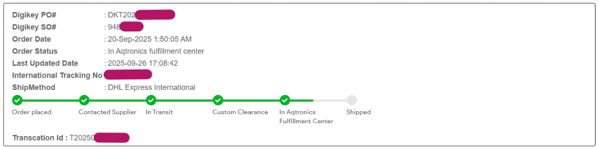
Quick update: I've placed the order on 20th Sept 2025, and will be shipped next week. I got my package on November 5, 2025.
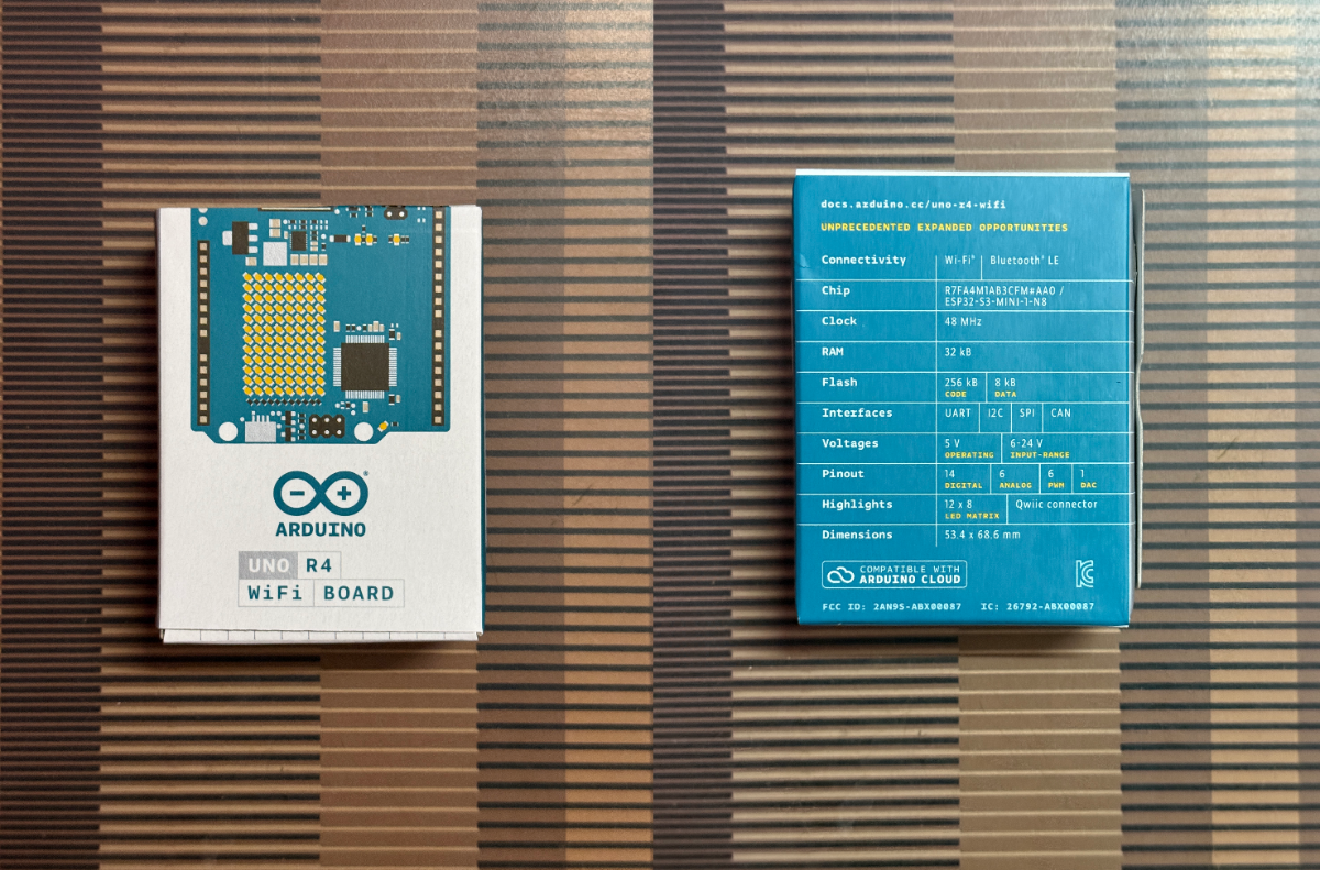
First Impression on the Arduino Uno R4 Wi-Fi
When you first open the box, you'll find the main attraction, the board itself which looks familiar but sports a significant upgrade with its powerful Renesas RA4M1 microcontroller and built-in Wi-Fi capabilities. Alongside the board, you can usually expect to see a safety guide, and perhaps a small sticker. What's often not included is a USB cable, so you might want to have one ready. The overall experience is straightforward, revealing a compact, well-designed board that's ready to bring your connected projects to life right out of the box.
Idea & Basic Setup
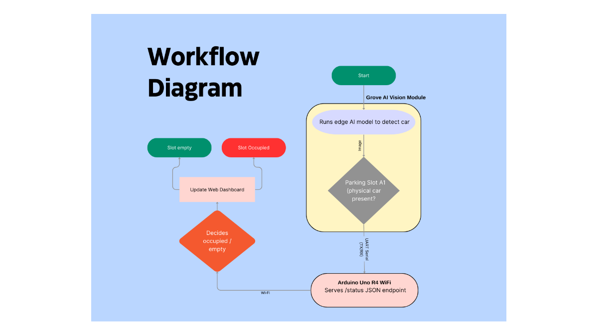
Workflow in detail:
Each parking slot (e.g., A1) has a small embedded node: an Arduino Uno R4 WiFi facing the slot with a Grove AI Vision Module running a SenseCraft-trained “car / no car” model. The Grove module performs all the heavy AI inference at the edge and streams simple serial data (for example, a label like car plus confidence) to the Uno via UART. The Uno parses this serial data, decides if the slot is occupied or empty, and keeps a local state variable for that specific slot ID (e.g., "A1").
The Uno R4 WiFi connects to the local Wi-Fi network and exposes a small HTTP endpoint (e.g., GET /status) that returns JSON like: {"slotId":"A1","occupied":true}.
A separate Smart Parking web dashboard (running on a laptop/PC or simple web server) periodically polls all slot devices (A1, A2, A3, …) by their IP addresses and updates the UI. Each card on the dashboard turns red for occupied and green for empty, providing a live view of the entire parking lot.
List of Components
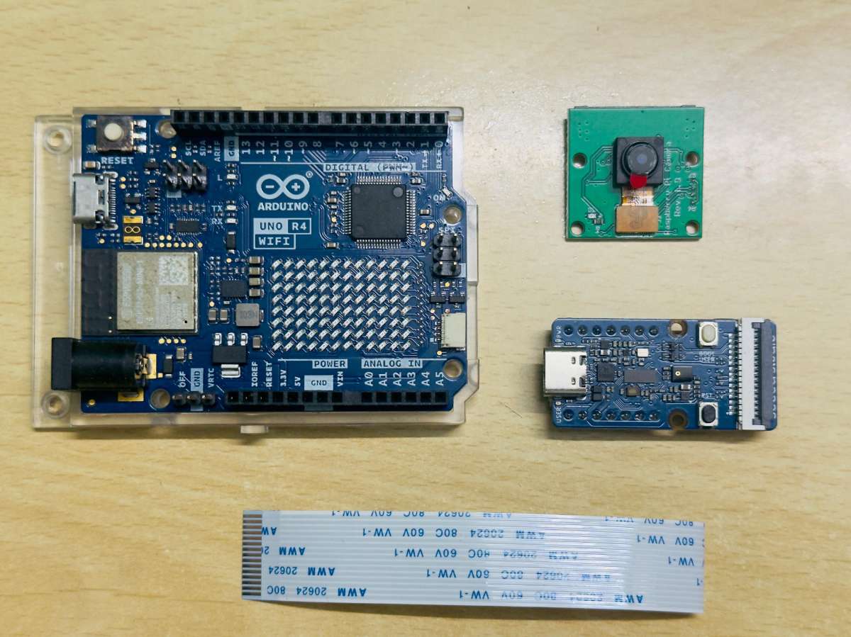
The following components are used to develop this project:
- Arduino Uno R4 Wi-Fi
- Raspberry Pi Camera 2
- SEEED Grove Vision AI module
- Raspberry Pi Camera CSI connector
Digikey Mylist : Click here to add these products using my DigiKey myList
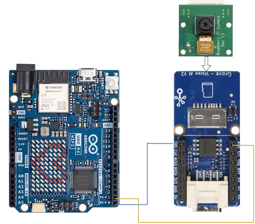
Connections
- Connect the CSI Camera to the Grove Vision Module as shown.
2. Connect the Grove - Vision AI V2 to your computer via USB.
3. Select USB Single/serial debug unit to connect
Uno R4 WiFi ↔ Grove AI Vision Module
- Grove AI Vision VCC → Arduino 5V
- Grove AI Vision GND → Arduino GND
- Grove AI Vision TX → Arduino RX1 (pin 0)
Grove AI Vision RX → Arduino TX1 (pin 1)
Implementation
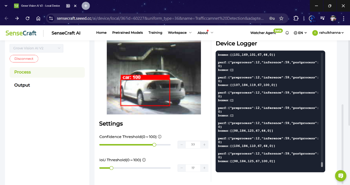
Configuring the Vision AI module
From the SenseCraft dashboard, the Vision AI device is detected automatically, allowing the user to select and deploy a pre-trained car detection model or train a custom classification model for “Car” and “No Car” classes. Sample images of the parking slot are captured directly from the live camera feed to build a small dataset, after which SenseCraft handles model training, optimization, and conversion for deployment on the module.
Once the model is deployed, the Vision AI module is configured to output inference results over UART (serial communication) in real time. Output format settings are customized to send detection labels, confidence scores, or simple status messages like car_detected or empty. The baud rate is matched with the Arduino Uno R4 WiFi configuration to ensure reliable communication. After setup, the module runs inferencing entirely on-device, producing fast and cloud-independent detection for each parking slot.
Arduino Operation
The Arduino Uno R4 uses the in-built Wi-Fi module for this project. It connects to local Wi-Fi network and reads serial lines from Grove AI Vision. If the line contains "car" with confidence above a threshold, it sets occupied = true else sets empty = true. Finally exposes GET /status endpoint returning JSON.
#include <WiFiS3.h>

const char* WIFI_SSID     = "YOUR_WIFI_SSID";
const char* WIFI_PASSWORD = "YOUR_WIFI_PASSWORD";

const char* SLOT_ID       = "A1";   // Change for each node: A2, A3, ...
const int   STATUS_LED_PIN = 7;     // Optional local LED

// Match this baud with what you configured in SenseCraft AI
const long  VISION_BAUD = 115200;   // Or 921600 if you set that in the module

WiFiServer server(80);

bool occupied = false;
unsigned long lastDetectionMillis = 0;
const unsigned long TIMEOUT_NO_CAR_MS = 8000;  // if no "car" for 8s -> empty

void connectToWiFi() {
  Serial.print("Connecting to WiFi: ");
  Serial.println(WIFI_SSID);

  int status = WL_IDLE_STATUS;
  while (status != WL_CONNECTED) {
    status = WiFi.begin(WIFI_SSID, WIFI_PASSWORD);
    delay(2000);
  }

  Serial.println("WiFi connected.");
  Serial.print("IP address: ");
  Serial.println(WiFi.localIP());
}

void processVisionLine(String line) {
  line.trim();
  if (line.length() == 0) return;

  Serial.print("Vision data: ");
  Serial.println(line);

  if (line.indexOf("car") != -1 || line.indexOf("Car") != -1) {
    // Try to find a confidence value (naive parsing)
    float conf = 1.0; // default if not found
    int commaIndex = line.indexOf(',');
    if (commaIndex != -1 && commaIndex < line.length() - 1) {
      String confStr = line.substring(commaIndex + 1);
      confStr.trim();
      conf = confStr.toFloat();
    }

    if (conf >= 0.60) { // threshold
      occupied = true;
      lastDetectionMillis = millis();
    }
  }
}

void handleClient(WiFiClient &client) {
  // Read the request line
  String requestLine = client.readStringUntil('\r');
  client.read(); // read '\n'

  // Ignore remaining headers
  while (client.available()) {
    String headerLine = client.readStringUntil('\n');
    if (headerLine == "\r" || headerLine.length() == 1) {
      break; // end of headers
    }
  }

  bool isStatusEndpoint = requestLine.startsWith("GET /status");

  if (isStatusEndpoint) {
    // Build JSON response
    String json = "{";
    json += "\"slotId\":\"";
    json += SLOT_ID;
    json += "\",\"occupied\":";
    json += (occupied ? "true" : "false");
    json += "}";

    client.println("HTTP/1.1 200 OK");
    client.println("Content-Type: application/json");
    client.print("Content-Length: ");
    client.println(json.length());
    client.println("Connection: close");
    client.println();
    client.print(json);
  } else {
    // Simple text response for root or other paths
    client.println("HTTP/1.1 200 OK");
    client.println("Content-Type: text/plain");
    client.println("Connection: close");
    client.println();
    client.print("Smart Parking Node ");
    client.print(SLOT_ID);
    client.print(" - Occupied: ");
    client.println(occupied ? "true" : "false");
  }
}

void setup() {
  pinMode(STATUS_LED_PIN, OUTPUT);

  Serial.begin(115200);   // Debug via USB
  while (!Serial) { ; }

  Serial1.begin(VISION_BAUD);  // Vision module UART
  delay(100);

  connectToWiFi();
  server.begin();
  Serial.println("HTTP server started on port 80");
}

void loop() {
  static String lineBuffer = "";

  while (Serial1.available() > 0) {
    char c = (char)Serial1.read();
    if (c == '\n') {
      processVisionLine(lineBuffer);
      lineBuffer = "";
    } else if (c != '\r') {
      lineBuffer += c;
    }
  }

  if (occupied && (millis() - lastDetectionMillis > TIMEOUT_NO_CAR_MS)) {
    occupied = false;
  }

  digitalWrite(STATUS_LED_PIN, occupied ? HIGH : LOW);

  WiFiClient client = server.available();
  if (client) {
    while (client.connected()) {
      if (client.available()) {
        handleClient(client);
        break;
      }
    }
    delay(1);
    client.stop();
  }
}
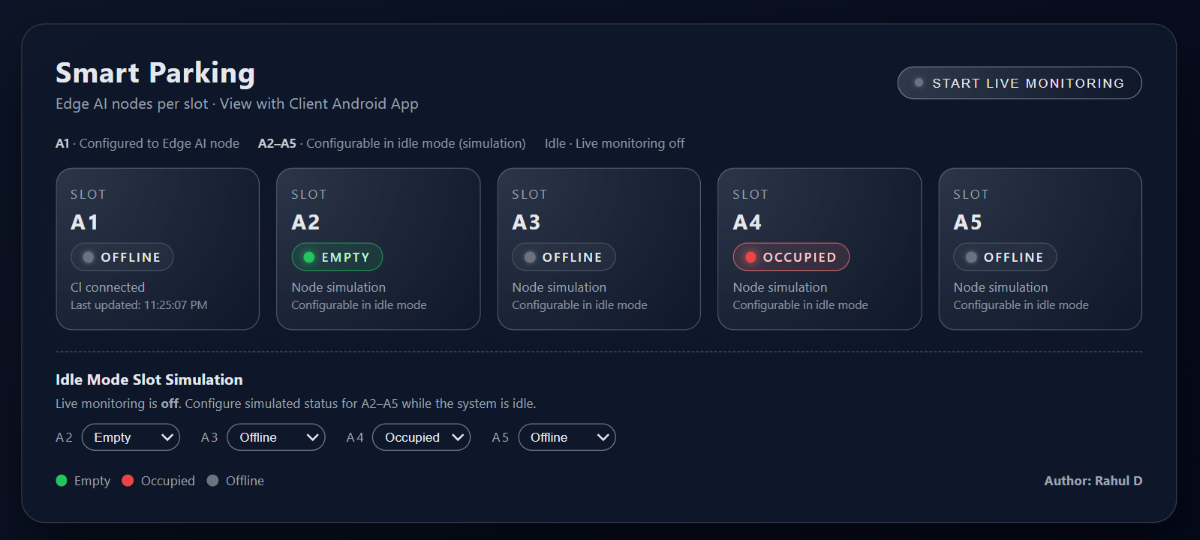
Web dashboard
Let's imagine a simple web page. Conceptual dashboard layout is shown here.
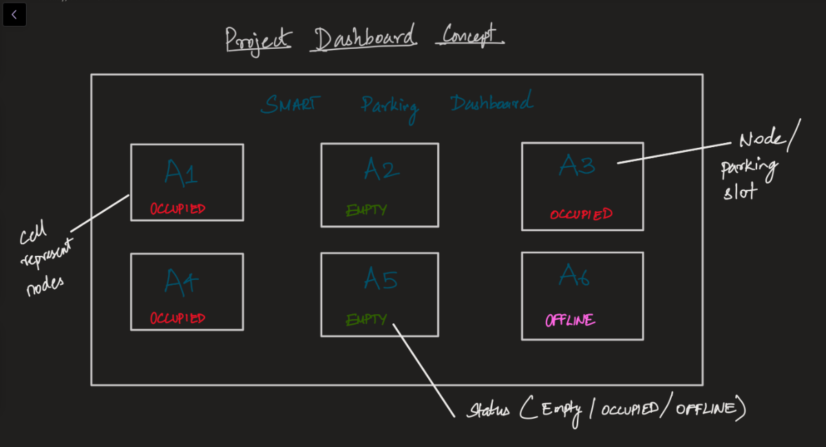
Each card corresponds to one Arduino+Vision node (each slot). Cards contains the information about the parking slot and the feedback from the device nodes. Based on the prediction from the Grove Vision sensor, the presence of the car is measured. The Status is one of the following categories: {Empty, Occupied, Offline}
Simulate “real” nodes using a local server (more realistic)
If you want to test the actual HTTP fetch calls, you can:
- Run a simple Node.js or Python server on your laptop.
- Expose multiple “fake node” endpoints, e.g.
http://localhost:3002/status→ A2http://localhost:3003/status→ A3
etc. Point the dashboard to
localhost:portinstead of real IPs.
Coding
Demo dashboard - Save this as temp_dash.html and open it in a browser on the same network as the Arduino nodes. Here, Node 1 is connected to the local server, and A2, A3 are not available and marked as Offline.
.png)
You’ll need to fill in the local IP address of each slot node (from the Arduino serial monitor when it connects to Wi-Fi).
Quick demo:
I've improved the Dashboard UI to make it appealing.
Here's the quick demo of the project. Voila !!
Future Scope
The system can be expanded into a full smart-parking ecosystem by adding navigation to the nearest free slot, automated billing, and integration with city traffic platforms. Each node operates independently over Wi-Fi using static IP, allowing hundreds of distributed slots across large parking areas to be monitored seamlessly with minimal infrastructure.