
Why Did We Build This?
The maintenance of the ambiance in places such as laboratories, especially chemical labs is essential. The temperature, humidity, and ambient light have to be monitored continuously and the level of air quality and heat levels are used as an interrupt to prevent the laboratory accidents.
Hardware Build
AVR-IoT WG Development Board:
- Go from out-of-the-box to cloud-connected in 30 seconds
- Onboard 8-bit MCU brings the processing power and simplicity of the AVR architecture with Core Independent Peripherals (CIPs) which further decrease power consumption
- Secure authentication with hardware-based private key storage
![]()
Features:
- ATmega4808 microcontroller
- TEMT6000 Light sensor
- MCP9808 Temperature sensor
- ATECC608A CryptoAuthentication™ device
- WINC1510 WiFi Module
- On-board nEDBG Debugger
- USB and battery-powered
- Integrated Li-Ion/LiPo battery charger
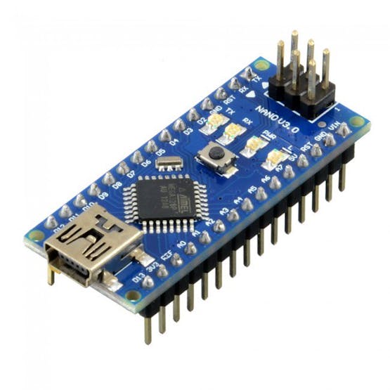
Arduino Nano:
Arduino Nano is a small board compatible with breadboards which is compatible with ATMega328. It has comparable usefulness to the Arduino Uno, however, when it comes to DIP module package, it works with a Mini-B USB link. This Arduino clone board is superbly compatible with Arduino IDE.
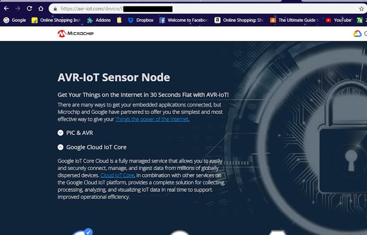
Step 1: Getting Started with Microchip's AVR-IoT WG Board
This board has an inbuilt temperature sensor and a light sensor which is a preloaded firmware that publishes the data from the sensors to the cloud.
The AVR-IoT WG development board features two sensors:
• A light sensor
• A high-accuracy temperature sensor - MCP9808
In addition to this, we use a few more sensors with Arduino that will be explained in the further part.
Step 2: Adding the Device to the Cloud
First, log in to the Google IoT core and create a new project and note your Project ID which will be needed later, when you program the hardware to connect to the project.
Note: Here I used a free trial account. Complete your billing procedure to enable the API.
In the Google Cloud console, you can find the IoT core in the sidebar.
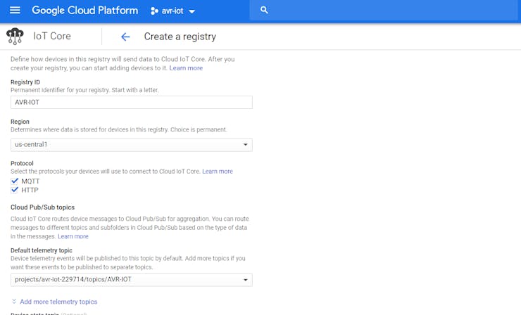
Create a registry:
To Register the device:
Note the Device ID from the Click me file, which will direct you to a link.
In the next form, Fill up the device ID with an alphabet at first, the Public key format is ES256 which can be verified, and add the PUBKEY.txt file on the add device page.
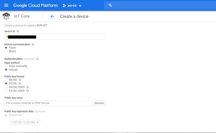
Now the device is successfully added to the Google Cloud.
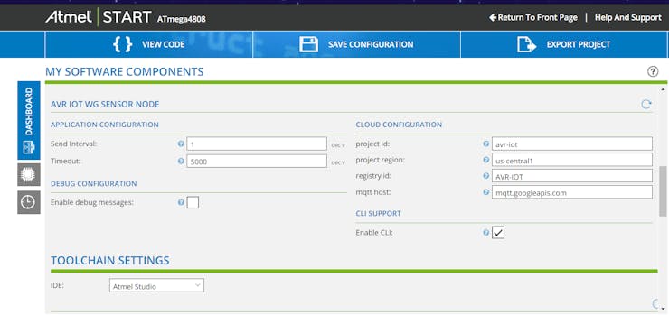
Go to the ATMEL START program and enter your Project ID, and Registry ID. i.e. Project ID: Avr-iot, Registry ID: AVR-IoT, and MQTT host: mqtt.googleapis.comin case of my project
Finally, Export the project to ATMEL Studio 7 and enable the debugger to start the program.
Step 3: Interfacing Other Sensors Using Arduino
Connecting the Peripheral to the Arduino:
Now we will see how to interface the other sensors with Arduino nano.
Interfacing DHT11:
The DHT11 sensor detects water vapor by measuring the electrical resistance between the two electrodes. The humidity sensing component is a moisture-holding substrate. When water vapor is absorbed by the substrate, the ions are released by the substrate which increases the conductivity between the electrodes. The change in resistance between the two electrodes is proportional to the relative humidity computed. Higher relative humidity(RH) decreases the resistance between the electrodes, while lower relative humidity increases the resistance between the electrodes i.e Relative humidity is inversely proportional to the resistance between two electrodes.
Here we connect the DHT11 temperature and humidity sensor to the digital pin of the Arduino.
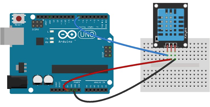
The Digital pin 7 of Arduino nano is used for the Output signal.
Connections:
Arduino ------------------------------------- DHT11
VCC(3.3v) -> Vcc(3.3v)
GND -> Ground(0V)
D7 -> Signal
The Temperature and the humidity from the DHT11 are calculated and stored in the variables which will be carried to the next section of the project.
Interfacing NeoPixel:
Then we connect the NeoPixel to the digital pin of the Arduino.
![]()
The Digital pin 2 of Arduino nano is used as Data IN.
Connections :
Arduino ------------------------------------- ----WS2816
VCC(3.3v) -> Vcc(3.3v)
GND -> Ground(0V)
D2 -> DI (Data IN)
The NeoPixel library is attached in the repository.
The NeoPixel ring which I had used is a 16-bit NeoPixel, i.e. the ring consists of 16 LEDs.
The color of the NeoPixel is switched depending on the temperature and humidity stored in the variables.
Interfacing BMP280 sensor:
The BMP280 air pressure sensor from Bosch gives the measured air pressure (ambient air pressure) and the ambient temperature as raw values, whereby the output can now be either via I2C or via SPI interface. But also the BMP280 waits with some improvements compared to the BMP180.
The default I2C address of the mapped module is 0x76 and can be changed to 0x77 with a solder bridge on the module.
Here I used SPI protocol to communicate with Arduino.
With the aid of 12 compensation parameters stored in the sensor, it is possible to determine the atmospheric pressure at the location (station level air pressure), altitude, and ambient temperature from the raw values.
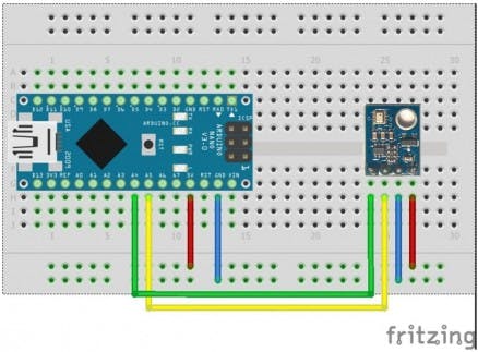
The I2C pins of Arduino nano are A4 & A5.
Connections :
Arduino ------------------------------------- BMP280
VCC(3.3v) -> Vcc(3.3v)
GND -> Ground(0V)
D10 -> CS
D11 -> MOSI
D12 -> MISO
D13 -> SCK
Interfacing Air sensor:
Here I interface MQ5 gas sensor which is a generic gas sensor available in the market which is more suited to detect and determine LPG concentrations.
This module has two output possibilities
- The analog output can be used to detect Gas leakage and to measure the volume of Gas leakage using certain algorithms which are implemented in the firmware and the level of Gas leakage is specified in ppm.
- The digital out can be used to detect Gas leakage. When there is a leakage of gas, an Interrupt is set by the Arduino which indicates the leakage of gas.
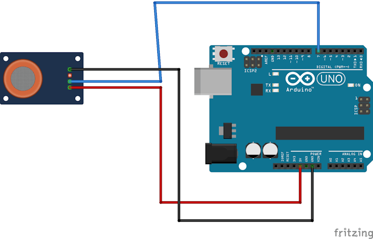
The digital pin 8 of Arduino nano is used for the Output signal.
Connections :
Arduino ------------------------------------- MQ5
VCC(3.3v) -> Vcc(3.3v)
GND -> Ground(0V)
D8 -> Data
Interfacing Buzzer:
A buzzer is added to the circuit to alert in case of an emergency.
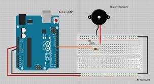
The digital pin 9 of Arduino nano is used for the Output signal which is a PWM signal.
Connections :
Arduino ------------------------------------------ Buzzer
D9 -> VCC
GND -> Ground(0V)
Step 4: Uploading the Firmware:
Before uploading the firmware, we have to create a bus to connect Arduino with the Microchip AVR-IOT-WG Board.
Connections :
Arduino ------------------------------------- Microchip AVR-IOT-Wg Board
VCC(3.3v) -> Vcc(3.3v)
GND -> Ground(0V)
D0 (RX) -> PC0 (TX)
D1 (TX) -> PC1 (RX)
Once the connection is done upload the code for sensors using Arduino IDE.
The code is added to the GitHub Repository which can be found in the code section.
In the case of Microchip, export the project from ATMEL start.
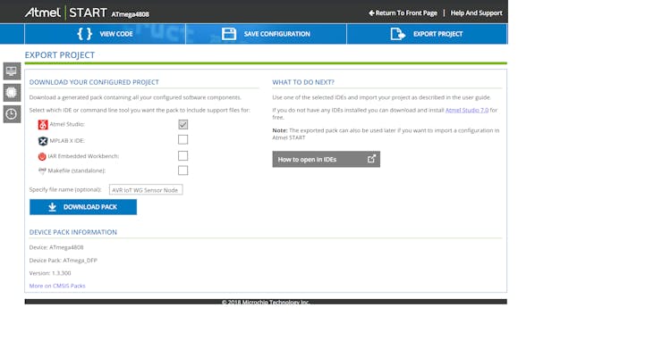
Select the solution configuration as release and debugger as UDPI as nEDBG.
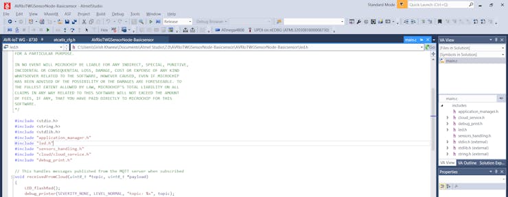
Finally, press the green arrow next to Solution configuration to start the program.
Note: Make sure that the program is properly uploaded without errors, i.e. you'll can find the writing process in the output dialog.
Step 5: Setting Up the Google Cloud for Publish and Subscribe
Create a new function in the Google Cloud Functions.
Set the following parameters:
- Trigger - Cloud Pub/Sub
- Topic - AVR-IOT
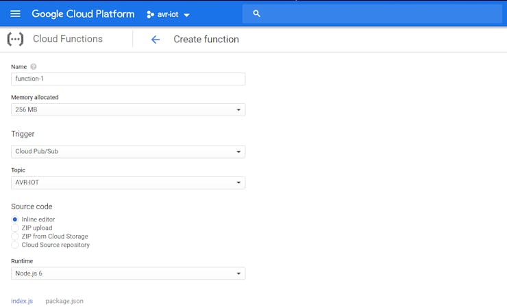
It automatically generates the code for PUB/SUB functions.
Step 6: Enclosure
I used an Acrylic enclosure for this project.
First, I placed all the circuitry inside the enclosure and screw it firmly.
I made a small opening for the Neopixel Ring and for the Light and Temperature sensor.
Finally, all the screws are firmly mounted and the power cable is inserted via a slot.
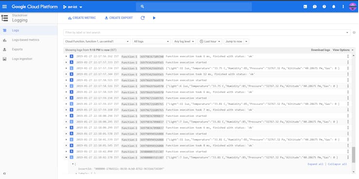
Step 7: Let's See It Working
You can find the data is being published on the Google Cloud.
This data which is logged can be display on either a website or with a mobile application.
Video:
Give a thumbs up if it really helped you and do follow my channel for interesting projects. :)
Share this video if you like.
Happy to have you subscribed: https://www.youtube.com/channel/UCks-9JSnVb22dlqtMgPjrlg/videos
Thanks for reading!