
1 Introduction
This project uses the Raspberry Pi Zero WH (RPZ) to control a four-wheeled robot car utilising the functions of the L298N dual H-bridge motor controller. Commands to the RPZ will be sent via a Smart Phone (Android or similar) using Bluetooth.
2 Components
The following components are required:-
- Raspberry Pi Zero
- 3 - 6V DC Motors (x 4)
- L298N Dual H-Bridge Motor Controller (x 2)
- Power Supply
- Connecting Wires
- Mecanum wheels (x 4)
- Laptop/Desktop/Smartphone
2.1 Raspberry Pi Zero W
The RPZ is a standard raspberry pi zero which has the normal wifi capability. At time of writing, the operating system in use is Raspbian Buster. The SD Card is also loaded with Python versions 2.7.16 and 3.7.3. This project will be using Python 3.7.3 (other version 3s are available).
2.2 DC Motors
Side elevation
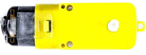
Aerial elevation
.png)
This is a standard 3-6v DC motor which includes a gear reduction mechanism to the rear of the motor (right, inside yellow casing). The gear ratio is 1:48, i.e. 48 turns of the motor spindle will turn the white axle once.
These DC motors are available at most retailers and are used quite frequently in the construction of robot cars. Four motors will be needed.
The current drawn by these motors varies between about 70mA and 250mA (maximum – approximately), so they are well within the tolerances of the L298N.
The terminals on these motors are quite delicate, so care must be taken when fixing (or soldering) wires to the motor, and also when manipulating the motor into position. The recommendation is to fix the wires to the motor, and then to wrap some insulating tape around the connections to minimise any connection movement. Snapping a terminal off the motor can render it unusable.
2.3 L298N Dual H-Bridge Motor Controller
The L298N motor controller is a very popular choice, and there are lots of documents on the web that explain the functionality of this device in great detail.
.png)
Two of these devices will be required, one for the left hand side and the other for the right hand side of the robot car. More on individual connections later in the document.
Please ensure that the 5V enable tag is in place.
2.4 Power Supply
.png)
In this project the Talentcell rechargeable 100Wh 5/9/12volt Lithium battery, model YB1208300-USB will be used. Other makes/models may be used as long as there is a separate 5volt supply for the RPZ and a separate supply for the dual L298N motor controllers. This particular Talentcell battery is convenient because not only does it have 3 power outlets, it can also be recharged in situ.
The 12V/6A (DC5521) output is used to power both the L298Ns, this output also doubles as the input for charging the battery.
The 5V/2A USB output is used to power the RPZ.
There is a spare 9V/1A (DC5525) output which could be used for low power activities such as temperature sensors etc.
The capacity indicator has 4 green lights, which will all be on when fully charged. Monitor these lights to warn you when you need to recharge the battery.
Lastly, the on (-) off (0) switch.
2.5 Connecting wires
This project uses 3 types of connectors :-
- Single/Multi core wire to connect the motors to the L298N controllers. Multi-core tends to be easier to manipulate. Either will do as long as they can carry a maximum of 2 amps.
- USB 2.0 or 3.0 to micro USB cable. This project uses a 10 inch length cable, which is long enough to connect the RPZ power socket to the battery 5V output socket.
- DC5521 plug to open ended wires. Once again this needs to be no more than 10 inches in length. This will connect the battery 12V output socket to both L298N motor controllers.
2.6 Mecanum Wheels
This robot uses 4 mecanum wheels (see main picture front page). These wheels are 80mm in diameter and approximately 40mm wide including hub lug. They have 9 diagonal rubber rollers each. The rubber rollers give a better holding performance when operated on laminated/wooden floors.
When fitting the wheels to the motors, ensure the rollers are positioned as in this diagram, where “Y” is the forward direction.
.png)
2.7 Laptop/Desktop/Smart phone
It is assumed that the RPZ is fully up to date and has Python 3.7.3 (or later) installed. The RPZ should also have Bluetooth enabled.
Ensure that SSH can be used from either of the above devices, as you will need to log in to your RPZ, enter Python 3.7 code, and enable Bluetooth.
3 Circuit Diagram
.png)
The following image shows the circuit diagram of the Raspberry Pi Zero (RPZ) using dual L298Ns to control 4 x DC Motors. It has been designed using the Fritzing Application.
4 Project Assembly
Find a suitable container (firm plastic or wood) and drill holes into the container so that the wires are able to pass into the container and that the motors can be attached using small metal brackets. The brackets, complete with small bolts, are shown here - https://thepihut.com/products/motor-mount-for-tt-gearbox-dc-motors-l-bracket-type
.png)
Attach the power wires to the motor and assemble the motor and the bracket and attach each motor to the underside of the container :-
.png)
There is an option to use a variety of the holes on the other side of the bracket, it is recommended that only the central hole be used as this will allow the motor to be positioned in parallel with the container. (NB: Using more than one hole in the bracket will require precision drilling of the container.)
At this stage leave the Mecanum wheels off.
When the four motors have been fitted to the underside of the container, and the respective power wires have been pushed through to the inside of the box, secure the L298Ns to the inside base of the box, and connect the motor power wires as per the previous circuit diagram.
.png)
Make sure that the battery is fully charged and in the OFF position.
In this project, the L298Ns have been positioned at the rear (or back) of the container. A black 5mm thick Perspex sheet (optional) has also been used to provide a sturdy base in this plastic container.
Now connect the RPZ to the respective L298N pins as follows :-
Top L298N to RPZ BCM(Physical Pin)
ENA brown wire 13 (33)
IN1 yellow wire 19 (35)
IN2 green wire 26 (37)
IN3 white wire 20 (38)
IN4 purple wire 21 (40)
ENB orange wire 16 (36)
Bottom L298N to RPZ BCM(Physical Pin)
ENA brown wire 17 (11)
IN1 yellow wire 27 (13)
IN2 green wire 22 (15)
IN3 white wire 24 (18)
IN4 purple wire 25 (22)
ENB orange wire 23 (16)
It’s a good idea to wrap some insulating tape around these wires to stop them flapping around.
Connect the ground (blue) on each of the L298N motor controllers to any of the RPZ ground pins, and also to the negative of the 12V battery lead. It’s a good idea to join both of the L298Ns ground and 12V terminals first, and then connect just one of the L298Ns to the RPZ and battery lead.
Connect both the L298N 12V terminals (red) to the positive of the 12V battery lead.
Place the battery into the container ensuring that the terminal descriptions are upper most (so you can see where the power slots are located).
Connect the RPZ to the battery using the 5V USB lead. Connect the 12V DC5521 jack to the battery.
Arrange the RPZ and wires so that they fit comfortably and safely into the container, and in a way such that the battery on/off switch can be reached easily. If there is a likelihood of the RPZ coming into contact with either of the L298Ns, use safety tape to avoid these from shorting.
Double-check ALL wiring.
The inside of the container should now look something similar to this :-
.png)
In this example, some padding has been used to stop the battery from moving in the container. Do not put padding around the RPZ or L298Ns as these will get warm during operation. If possible, drill/cut holes through the box/container near to the L298Ns as this will allow air to circulate around to keep them cool.
5 Initial Testing
An initial test is required to ensure that all the motors are connected correctly, and more importantly that they all turn in the correct direction as dictated by the program.
Making sure that the L298N power lead (DC5521 12v) is plugged into the Talentcell battery, and that the Mecanum wheels are not fitted to each motor, place the robot car on to a flat surface with the motors downwards i.e. battery and RPZ upwards.
Connect the RPZ micro power socket to the Talentcell battery (USB 5v), if not already done.
Turn the battery switch to the on position “-”.
Wait for a few minutes while the RPZ starts up and goes through its initialisation process.
From a laptop, desktop or Android connect to the RPZ using VNC viewer. VNC viewer can be downloaded and installed from here - https://www.realvnc.com/en/connect/download/viewer/. There are several android based apps that can help find the IP address of the RPZ if not known prior to using VNC viewer.
Once connection is established, logon in the usual manner (this will depend on the original setup of the RPZ), store the following python3 program onto an area of the RPZ, and run the program via SSH, no need for Bluetooth at this stage.
from gpiozero import Motor, OutputDevice
from time import sleep
import os

m1 = Motor(19, 26)                              # Assign motors
m2 = Motor(20, 21)
m3 = Motor(27, 22)
m4 = Motor(24, 25)

m1_enable = OutputDevice(13, initial_value=1)    # Enable all motors
m2_enable = OutputDevice(16, initial_value=1)
m3_enable = OutputDevice(17, initial_value=1)
m4_enable = OutputDevice(23, initial_value=1)

speed = 0.2                                     # Set motor speed

print("Forward")
m1.forward(speed)
m2.forward(speed)
m3.forward(speed)
m4.forward(speed)

sleep(10)

print("STOP")
m1.stop()
m2.stop()
m3.stop()
m4.stop()
This program should run the motors in a forward direction for 10 seconds. Whilst the program runs, check each motor axle in turn to ensure that they are all turning in the same direction. Rerun the program as required.
If any motor is not turning in the correct direction, wait for the program to end, shutdown the RPZ, power off, and swap the wires of the terminals on the appropriate L298N that are not turning in the required direction. Turn on power and repeat above process until satisfied that wheels are in sync.
All motors must be turning in unison and in the correct direction before proceeding.
6 Setting up the Blue Dot on Android
Download and install Blue Dot application onto the Android device.
The android will not connect with the RPZ until the main program is run. This can either be done via a Mobile VNC or SSH app, or VNC/SSH from a laptop or desktop PC.
When running, the Blue Dot controls will look like this on the android screen :-
.png)
RED = Forward, Backward, Left or Right
YELLOW = Shift Left or Right (crab L/R)
GREEN = Slide Left or Right (diagonal forward L/R)
BLACK = Pause
BLUE = Quit
WHITE = Not activated
These controls and colours can be changed within the python program.
(NB: At time of writing, it was not possible to place text into the various circles)
7 Fitting the Mecanum Wheels
Having made sure that all the motors run in the correct direction, as per section 5, place the Mecanum wheels onto the motors as per the following diagram (source : Wikipedia) :-
.png)
Using diagram a) as a guide, and ensuring that the forward motion of the motors is in the direction of ”y”, (as if looking down on the robot car), place the wheels onto each motor so that the angle of the rollers is the same as indicated in the diagram.
The remaining diagrams b) to f) show the effect of robot car movement depending on the direction of the individual motor indicated by the blue arrow (NB: not all are used in this project).
8 Sequence of Operation
- Plug in power to RPZ and L298Ns and turn on Robot Car
- Place Robot Car on level surface away from obstacles.
- Turn on Android/Laptop/Desktop
- Turn on Bluetooth on Android/Laptop/Desktop
- VNC into Robot Car RPZ (may require several attempts if RPZ not ready)
- Turn on RPZ Bluetooth via VNC
- Locate and run main python program (program will wait for event)
- Activate Blue Dot app on Android
- Pair Android with RPZ, see link for full instructions :-
(https://bluedot.readthedocs.io/en/latest/gettingstarted.html)
- Select connection of Android to RPZ.
- (Coloured controls will now appear – as per Section 7)
- Practise to perfect your technique !
During operation, the L298Ns may get quite hot. DO NOT TOUCH THEM and DO NOT run the program at full speed for any length of time, and, avoid obstacles and rough terrain which would otherwise cause stress to the motors, and hence cause the L298Ns to overheat. Speed = 0.3 is fast enough until you get used to the controls.
Lastly, Remember to Power down the RPZ and switch off the battery when finished.
9 Design note
When running the robot forward in a straight line, the robot may tend to veer slightly to one side. This is because not all the motors rotate at the same frequency, despite being powered by the same voltage. To improve this, the speed can be altered for the offending motor(s), by setting up speeds for each individual motor – it can be a little bit trial and error until it becomes consistent.
The L298N 5V output socket is not used in this project, but may prove useful for powering low current activities such as temperature monitoring etc.
10 Main Program
The following is a copy of the original main program. It can be changed to suit the individual’s requirements :-
from gpiozero import Motor, OutputDevice
from bluedot import BlueDot
from time import sleep
import os

bd = BlueDot(cols=5, rows=3)    # Setup android control buttons
bd.color = "red"                    # Motion buttons in red, except...
bd.border = True
bd[2,1].color = "blue"           # Quit button in blue
bd[0,0].color = "green"         # Shift buttons green
bd[0,1].color = "yellow"        # Slide buttons yellow
bd[4,0].color = "green"
bd[4,1].color = "yellow"
bd[0,2].color = "black"         # Pause buttons black
bd[4,2].color = "black"

bd[1,0].visible = False         # Blank out other squares in block
bd[3,0].visible = False
bd[1,2].visible = False
bd[3,2].visible = False

m1 = Motor(19, 26)              # Assign motors
m2 = Motor(20, 21)
m3 = Motor(27, 22)
m4 = Motor(24, 25)

m1_enable = OutputDevice(13, initial_value=1)    # Enable all motors
m2_enable = OutputDevice(16, initial_value=1)
m3_enable = OutputDevice(17, initial_value=1)
m4_enable = OutputDevice(23, initial_value=1)

speed = 0.3                       # Set motor speed

def forward():
       print("Forward")
       m1.forward(speed)
       m2.forward(speed)
       m3.forward(speed)
       m4.forward(speed)

def backward():
       print("Backward")
       m1.backward(speed)
       m2.backward(speed)
       m3.backward(speed)

def left():
       print("Left")
       m1.forward(speed)
       m2.forward(speed)
        m3.stop()
        m4.stop()

def right():
        print("Right")
        m1.stop()
        m2.stop()
       m3.forward(speed)
       m4.forward(speed)

def shiftl():                   # Crab left
       print("Shift Left")
       m1.backward(speed)
       m2.forward(speed)
       m3.forward(speed)
       m4.backward(speed)

def shiftr():                   # Crab right
       print("Shift Right")
       m1.forward(speed)
       m2.backward(speed)
       m3.backward(speed)
       m4.forward(speed)

def slidel():                  # Forward diagonally left
       print("Slide Left")
        m1.stop()
       m2.forward(speed)
       m3.forward(speed)
        m4.stop()

def slider():                   # Forward diagonally right
       print("Slide Right")
        m1.forward(speed)
        m2.stop()
        m3.stop()
       m4.forward(speed)

def pause():
       print("PAUSE")
        m1.stop()
        m2.stop()
        m3.stop()
        m4.stop()

def quit():
       print("STOP")
        m1.stop()
        m2.stop()
        m3.stop()
        m4.stop()
        sleep(2)
       os._exit(0)                       # Exit program

while True:                               # Continuous loop

       bd[2,0].when_pressed = forward   # Check which button pressed and call subroutine
       bd[2,2].when_pressed = backward
       bd[1,1].when_pressed = left
       bd[3,1].when_pressed = right
       bd[0,0].when_pressed = slidel
       bd[4,0].when_pressed = slider
       bd[0,1].when_pressed = shiftl
        bd[4,1].when_pressed = shiftr
       bd[0,2].when_pressed = pause
       bd[4,2].when_pressed = pause
       bd[2,1].when_pressed = quit