

A number of projects that are already available at different companies with regard to the development of automated vehicles. In the past few years, there has been a huge development towards automation in agriculture industry. Some of the methods for the development of automated vehicles are:
1. Fabrication and Automation of Seed Sowing Machine using IOT: The procedure works manually. From this we had learned to design our vehicle physically and we learned the mechanism of seed sowing and mechanism of ploughing and watering the soil. Basically this mechanism runs on controllers and relays. In this operation, commands are given through controllers or through android mobile phones the motor transmits motion to the front wheels through belt and pulley mechanism. The main limitations related to this project are manually humans should move vehicle and there is no pre-defined path to move the robot.
2. Wireless control of an automated guided machine: Method of inter-robot network: This paper includes, the implementation of mechanism is based on radio frequency and by using piccontroller. Generally this AGV (automated guide vehicle) is termed as rover. This mechanism requires many IR sensors. It has main critical path .By using the IR sensors it will sense the directions and moves along the critical path. This mechanism works on 2-bit data path coordinates that need to be appropriately entered by the user depending on the path actions. The limitations related to this project are by using so many IR sensors there is a problem that they may or may not work some times. If any damage in transceiver and receiver then bit communication will get stopped. So robot will not move anymore. It requires users and moreover less awareness in humans to operates the bit data path.
3. Seed Sowing Robot: This is an automated robot in agriculture. When the user presses the commencement button the robot commences moving in forward direction.. As we have already programmed the working of robots in microcontroller. When the robot started moving towards, at a certain distance it ceases and then it starts the drilling mechanism. In this procedure so many electronic components like IR sensors, solenoid valve and many ICs are used. So the main limitations related to this project are these electronic components will not sustain the moving vibrations and high temperature. And also accuracy should be reduced due to clay or mud.
BLOCKDIAGRAM:
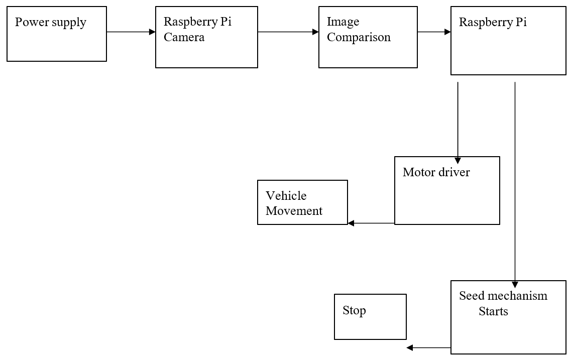
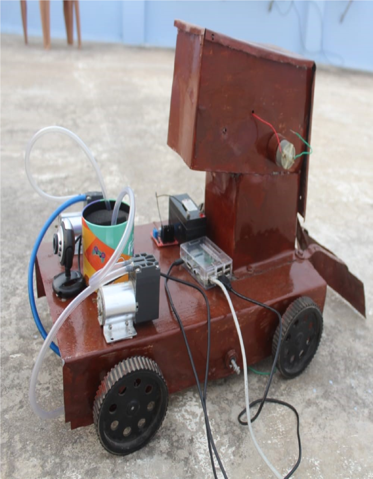
In this project, we made an attempt to reduce the complexities faced by farmers by creating an autonomous vehicle which is able to indicate plant health along with sprinkling water/spraying pesticides to the entire field. If the robot is set to move in an area, this is done using pi-camera. The robot is trained along the path using machine learning and then a web camera is connected using a USB port on raspberry pi that is used for live video streaming. The movement of the robot whether it moves overview of the surrounding in which it moves is all obtained with the help of web-camera. This can help in detecting and tracking the objects and people. Then the robot move automatically by sprinkling the water, drilling seed, pouring seeds and then covers the surface.
OPERATION:
The robot is to be trained at the initial stage. For any movement of robot the enable pins need to be given 5V. The camera present in the robot will continuously captures the images. When any image satisfies the robot turning position criteria based on the sign robot will turn to the direction.
- SEED DRILLING STAGE:
In this stage the robot is having a seed container where the seeds will be poured into it before the start of the movement itself.
When the supply is given through raspberry pi (5v) the sprocket to distribute the seeds will start picking the seeds and will pour to the ground.
And just before the seed touching the ground robot is attached with a plow and it is also attached with a softener where is will close the sand.
2. WATER SPRAYING SYSTEM:
A pump motor which is placed at a certain height on the robot is fixed with nozzles in right and left positions on the robot. The outputs of the vacuum pumps are connected to the nozzles.
DESIGN FLOW:
IMAGE PROCESSING:
The pie camera takes the image of the fields.
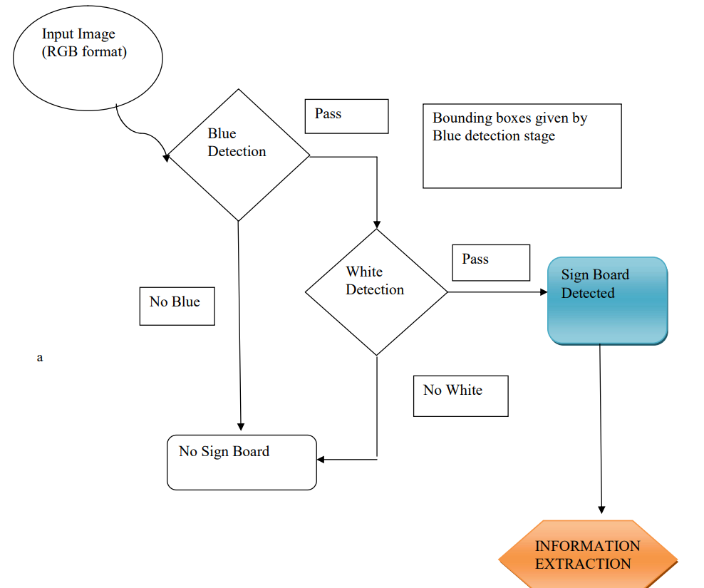
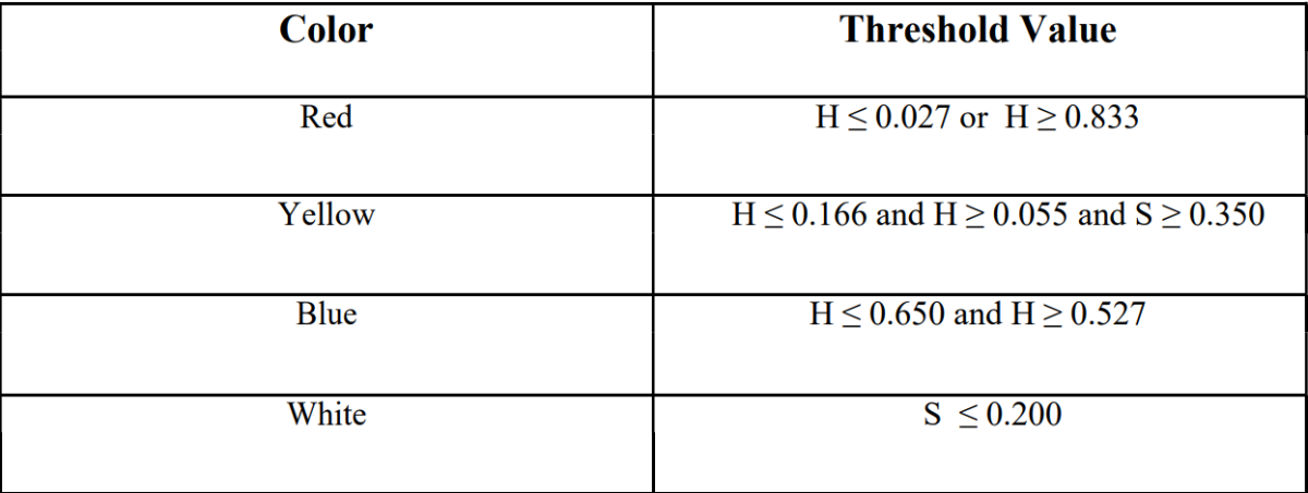
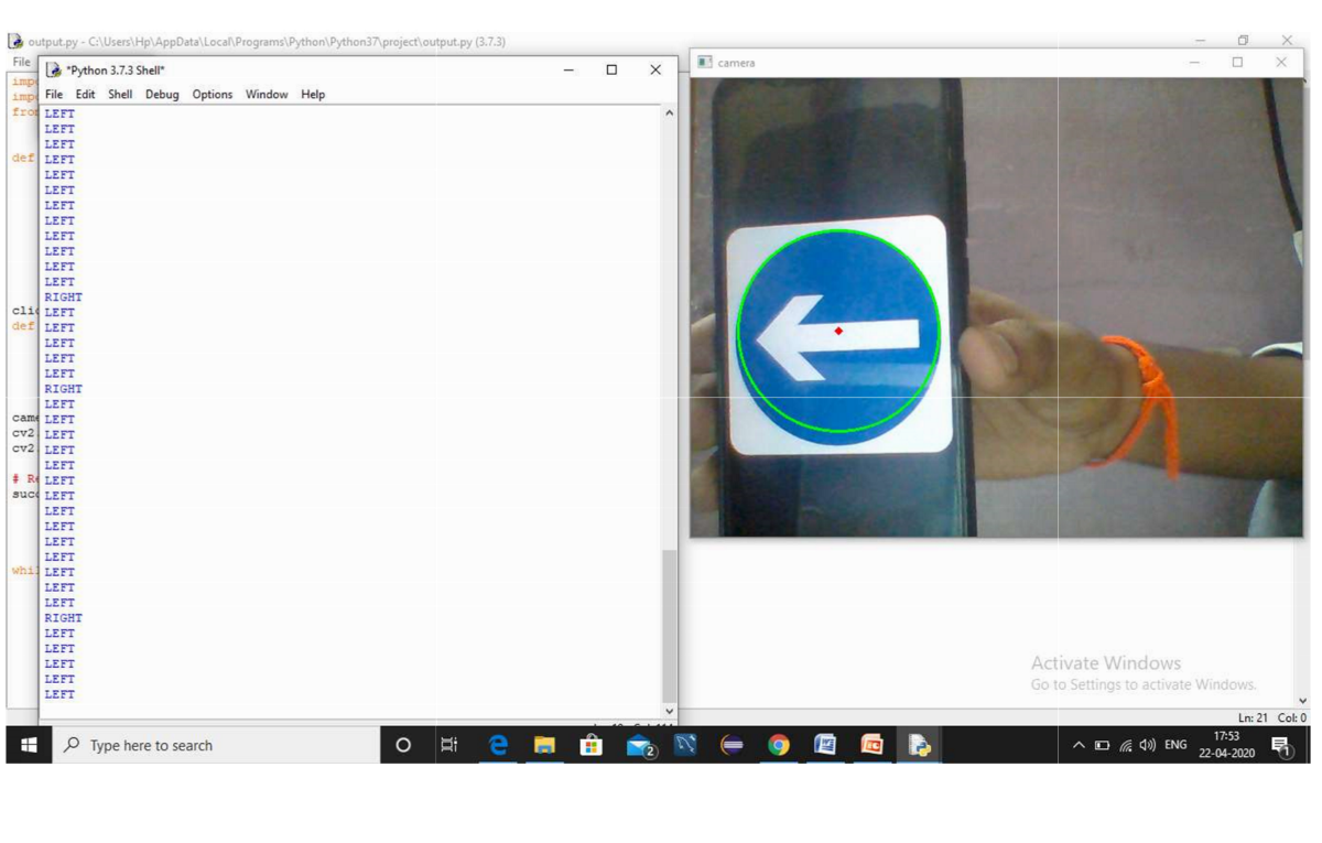
By using the algorithm which is developed by using the HUE saturat ion Intensity (HSI)color space to segment the road sign color and ROI in order to locate and determine the shape of the road sign.
The image is processed in three phases to get the path in which direction the robot has to move.
The development of the image processing has two major objectives.
- Segmentation of road sign by using color information from real images with the help of threshold technique.
- Classification of road signs based on the region of interest determined by color segmentation stage.
COLOR SEGMENTATION:
From the real images, the regions of the road sign colors re segmented from by use HSI color thresholding technique.
For the segmentation of achromatic color, achromatic color decomposition technique is used.
SHAPE CLASSIFICATION:
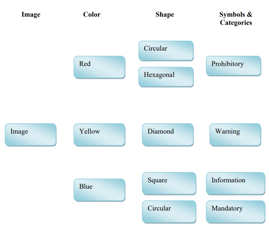
By computing extent values the shapes of the road signs are classified into four patterns.
- Prohibitory
- Warning
- Informational
- Mandatory
SYMBOL RECOGNITION:
By comparing shape measurement the symbols of road signs are recognised Most road signs are detected and recognized by the method with the accuracy of 90.7% in the segmentation phase and has the accuracy of 98.3% in classifying the shapes of road
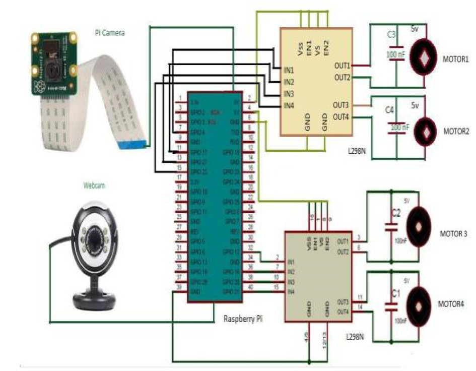
CIRCUIT DIAGRAM:
The circuit diagram states that the seed sowing vehicle is attached with 2 Motor drivers which controls the 4 DC motors and also for movement of bot it is having webcam which is used for road sign detection as well as vehicle movement can also be done with help of webcam.
Step 1: Reformat your micro SD card
The first step to getting started with Raspberry Pi is to reformat the micro SD card that you will use to download the operating system. Even brand new SD cards will have some extraneous files on them. Reformatting it will remove all files and completely clear the card. Insert your micro SD card into the USB card reader.
Screenshot regarding SD card formatter
Under Select Card select your micro SD card from the dropdown menu. Click format in the bottom right corner.
When the reformat is complete, you will get a notification window. Select OK to close the window.
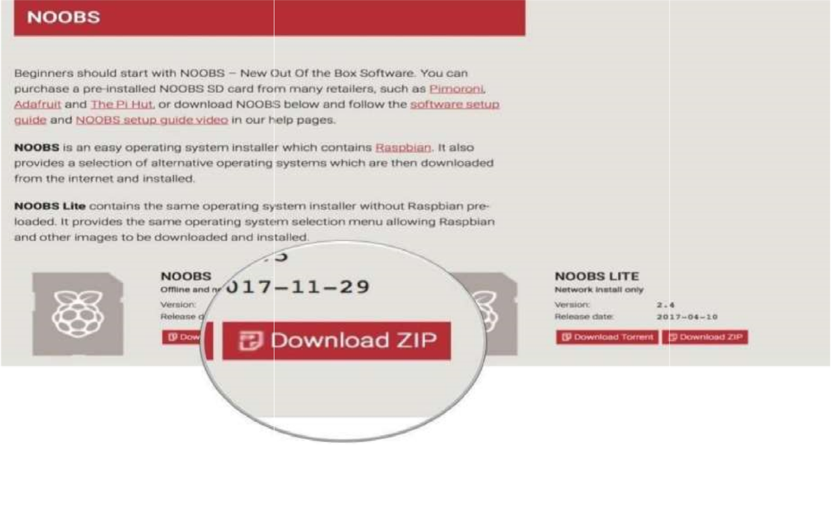
Step 2: Download NOOBS onto the micro SD card
The next step is to get NOOBS onto the micro SD card. Once it's loaded, you can plug it into your Raspberry Pi and configure the operating system. The micro SD card should already be connected to your computer at this time.
1 .Download the ZIP files of NOOBS Version 2.4.5. It is a large file and will take a while to complete. You will want Raspbian, so do not download NOOBS Lite.
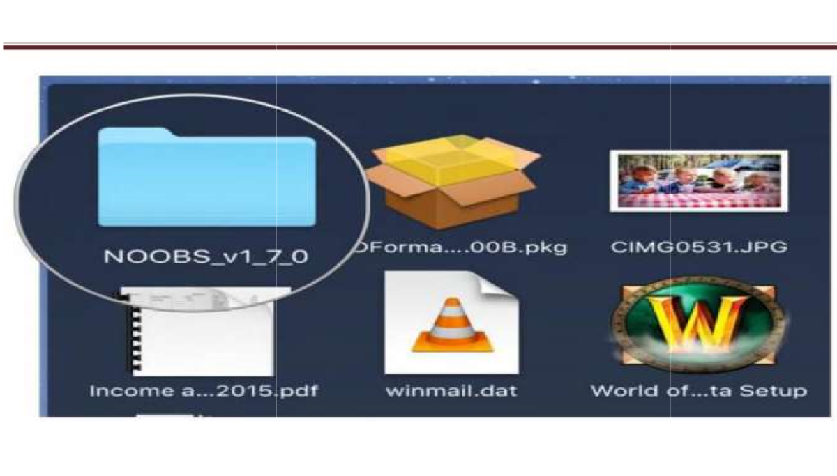
- Couble-click on the NOOBS file from the Downloads folder in your Dock to open it.
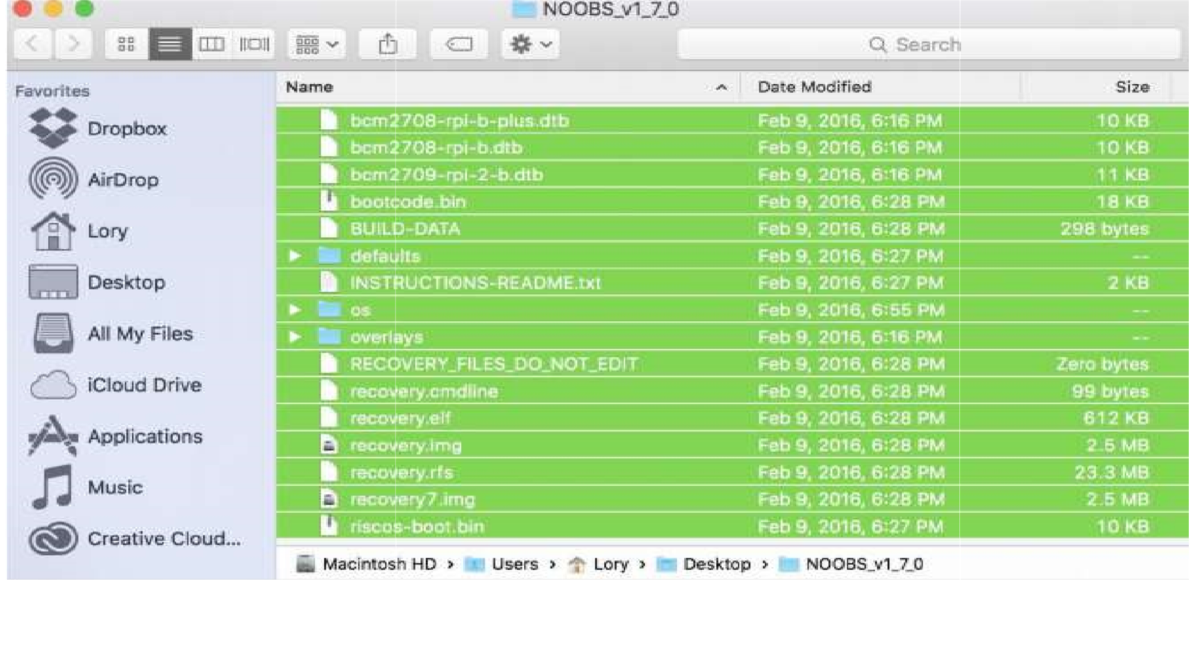
- Select the first file inside the NOOBS folder.
- Scroll down and Shift + left-click on the last file in the NOOBS folder.
- Drag and drop all selected NOOBS files into the SD card icon on your desktop. You don't have to open the SD card drive.
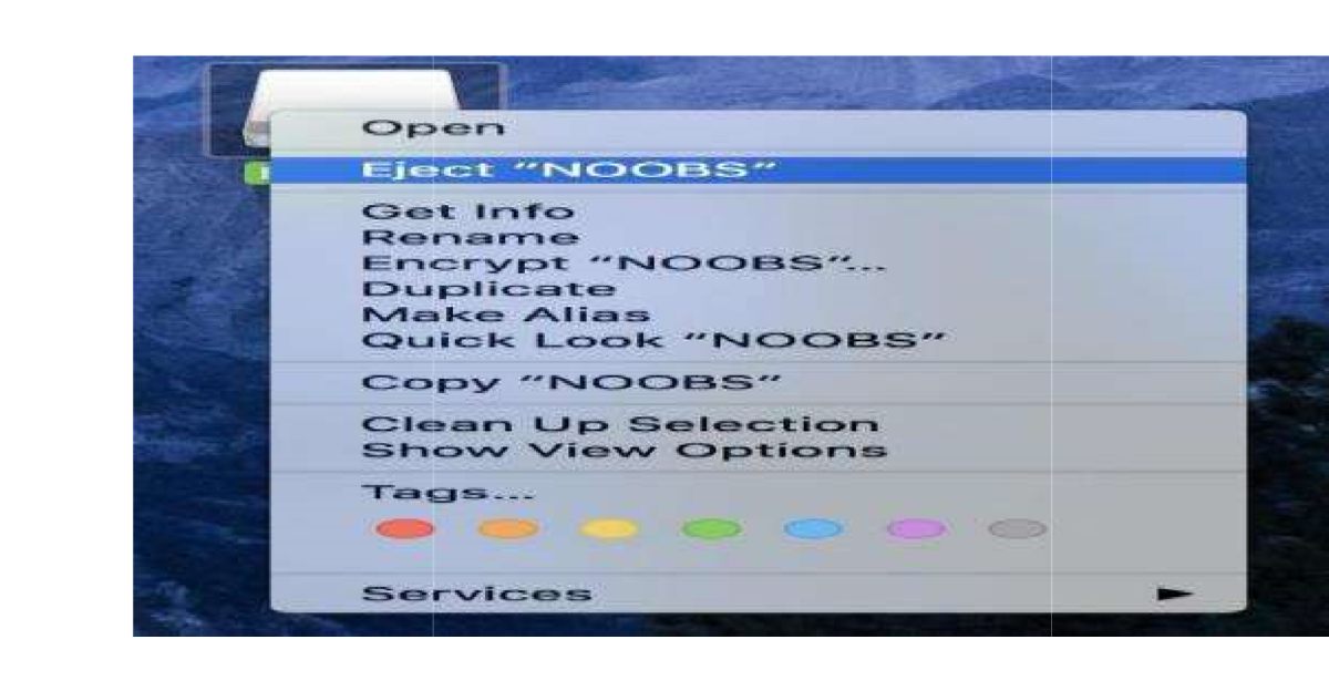
- Right-click on the SD card icon.
2. Select "Eject [SD Card Name]".
- Remove the card reader from your computer.
- Remove the micro SD card from the card reader.
Step 3: Set up your Raspberry Pi
- Insert the micro SD card into the card slot on the underside of the Raspberry Pi.
- Plug the USB keyboard into one of the USB ports.
- Plug the USB mouse into one of the USB ports
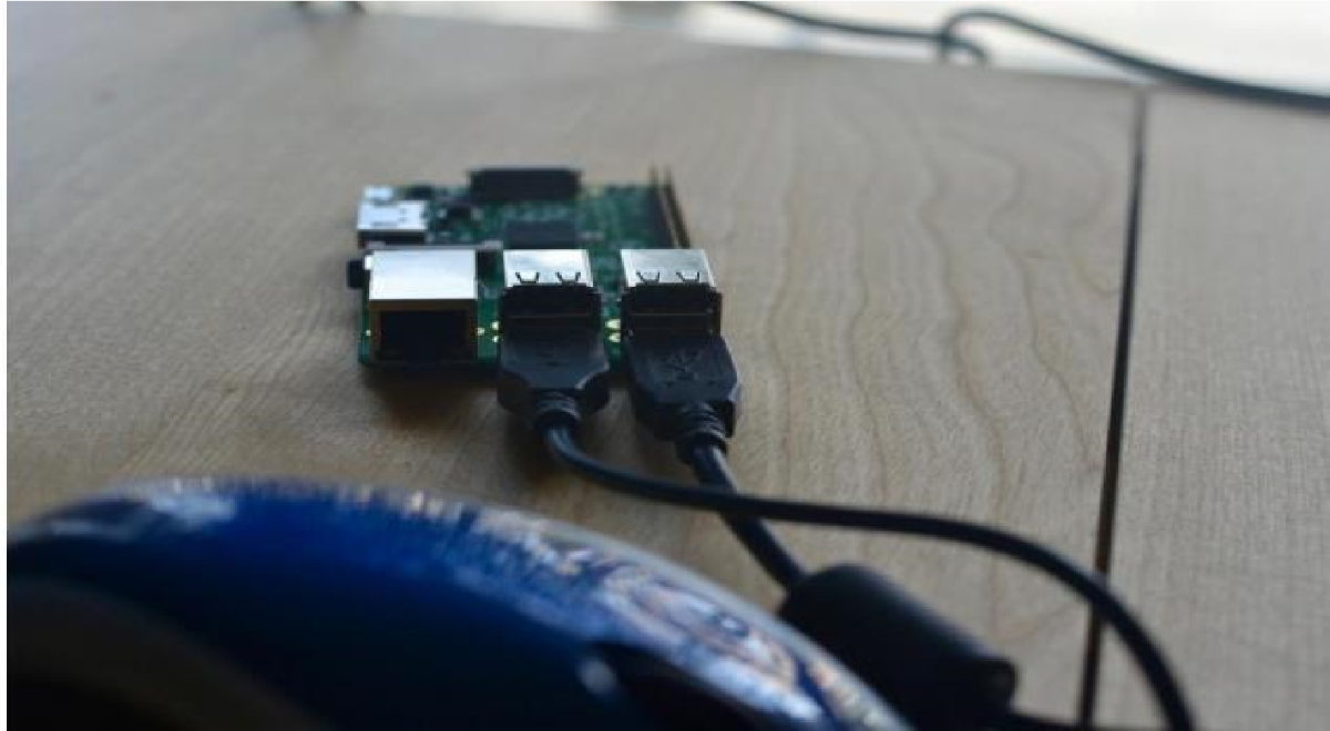
Turn on your monitor or TV set and make sure it is set to the proper input (e.g. HDMI 1 or Component)
4. Plug the HDMI or video component cable into the monitor or TV set.
5. Connect the other end of the cable into the Raspberry Pi.
.png)
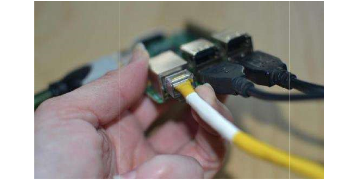
6. Connect an ethernet cable to your router if you plan to connect to the Internet.
7. Connect the other end of the cable to your Raspberry Pi.
8. Alternately, connect the Wi-Fi adapter to the Raspberry Pi.
9. Connect the power supply to the Raspberry Pi.
10. Plug the power supply into the power outlet. This will turn on and boot up Raspberry Pi. A power indicator light will begin to glow, letting you know that you are connected.
Step 4: Download the Raspbian operating system on the Raspberry Pi
Beginners should start off using the Raspbian operating system. It is the easiest to use and there are hundreds of projects out there that use the Raspbian operating system. If you want to use a different operating system later on, you can reconfigure your Raspberry Pi then.
Once you have successfully followed the steps above, a start screen will appear on your monitor or TV. 1.Select Raspbian.
2.Click Install.
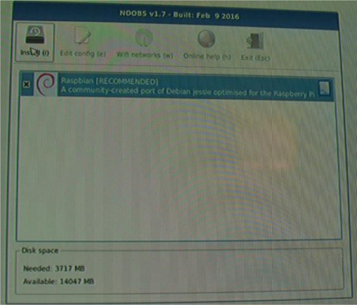
3.When the warning window pops up. Click yes to confirm.
4.This is just letting you know that the micro SD card will be overwritten with an uncompressed version of the Raspbian operating system.
5. Wait for the installation process to complete.
Once the installation process is finished, Raspbian will automatically begin to boot.
Step 5: Configure your Raspberry Pi
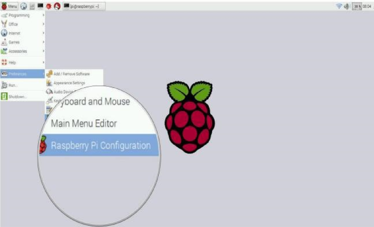
When Raspbian begins to load a bunch of lines of code will appear. This will continue until the boot process has completed. Then, the Raspbian Home screen will appear. You will need to configure your Raspberry Pi system in order to add your location, date, and time.
- Click Menu in the upper left corner of the screen.
.png)
2. Select Preferences in the dropdown menu.
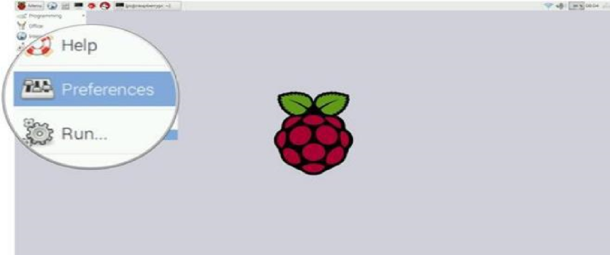
3. Select Raspberry Pi Configuration under Preferences.
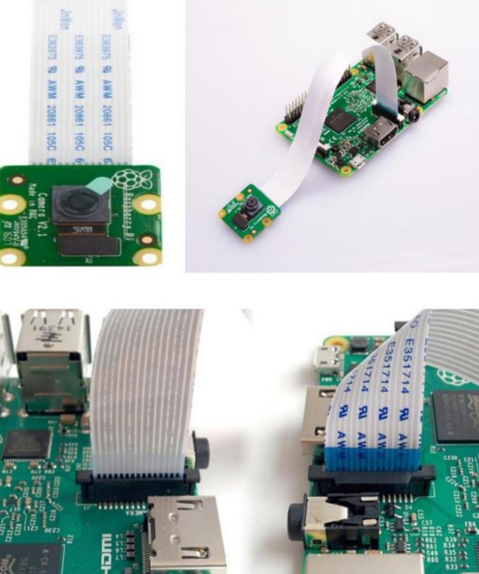
Connect the Camera Module
Ensure your Raspberry Pi is turned off.
- Locate the Camera Module port
- Gently pull up on the edges of the port’s plastic clip
- Insert the Camera Module ribbon cable; make sure the cable is the right way round
- Push and plastic clip back into place
L298N MOTOR DRIVER:
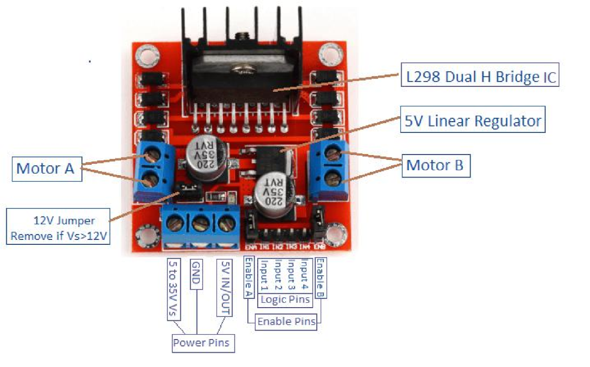
L298N motor driver is used to drive high loads which requires much more current like a motor.L298N motor controller follows the H-bridge configuration, which is handy when controlling the direction of rotation of a DC motor. Benefit of H-bridge is that you can provide a separate power supply to the motor. Remove the +12 v jumper, if you are using power higher than +12v. when the +12v jumper is attached, the on-board voltage regulator is now enabled, and you can source +5v from the +5v from the +5v terminal. Enable pins, input pins up to +5v are connected to microcontroller. +12v is connected to the external power source with a common ground shared with +5v. Actually, this pin can accept +7v to +35v.
WORKING:
A regulated power supply is very much essential semiconductor material employed in them have a fixed rate of current as well as voltage. The device may get damaged if there is any deviation from the fixed rate. The AC power supply gets converted into constant DC by this circuit. By the help of a voltage regulator DC, unregulated output will be fixed to a constant voltage.
The circuit is made up of linear voltage regulator 7805 along with capacitors and resistors with bridge rectifier made up from diodes.
From giving and changing voltage supply appliance, the diodes along with capacitors handle elevated efficient signal conveyed.
As we have previously talked about that regulated power supply is a device that mechanized on DC voltages and it can uphold its output accurately at a fixed voltage all the time although if there is a significant alteration in the DC input used in the circuit to maintain the exact voltage which is followed by the power supply.
A regulator is mainly employed with the capacitor connected in parallel to the input terminal and the output terminal of the IC well as in the output filter, capacitors are used.
While the bypass capacitors are used to check the small period spikes on the input and output level.
Bypass capacitors are mainly of small values that are used to bypass the small period pulses straight into the regulated IC of 5V.
SOFTWARE REQUIREMENTS:
In this project for the movement of bot we use road sign detection and recognition system. Road signs provide information which helps the bot to move in different directions. Road sign information which we provide are categorized in to colors and shapes for easy identification. Using image processing road sign detection technologies are developed. This system development is divided into two major objectives
1. Color threshold technique is used for segmentation of road signs using colors information from real image.
2. Classification of road signs predicated on the region of interest determined by the color segmentation stage.
There are many techniques have been developed for the detection and recognition. The design of road sign detection and recognition algorithm is of two phases; Detection and Recognition.
The most common method apply for initial detection of road signs is color segmentation.
A theory was proposed by with three phases which are
1. Color Segmentation
2. Shape Detection
3. Sign Classification
These three theories are proposed using neural network. In order to reduce processing time they use RGB color space.
In recognition phase, simple models of pattern matching, edge detection and geometrical cues are employed.
COLOR SEGMENTATION : By using HIS(Hue Saturation Intensity) color thresholding technique , the roads sign colors are segmented from real images. In addition white signs from images are detected by using achromatic color decomposition technique.
SHAPE CLASSIFICATION: Generally road signs are classified into four categories .They are: Prohibitory, Warning, Informational and Mandatory. These are classified by computing extent values.
SYMBOL RECOGNITION: By comparing shape measurements the symbols of road signs are recognized. These measurements are area and perimeter with different values. These template values are based on standard images without noise.
Phase 1: Color Segmentation:
The HSI color space is related to the human sensitivity of colors. To extract road sign colors in a real environment based on fixed thresholds, hue and saturation elements are sufficient. The Hue elements indicate the perceived colors i.e., red, yellow, blue which are within the interval[0,360].

Where R, G N And B Are The Brightness Of Individual Colors, And D Is the Extraction Degree Of Achromatic Color where D Is Set To 20. The Fig-2 Shows The Ranges Of Red Color Are Within The Interval [0,60] And [300,360]. The Hue Element Is Normalized To The Range [0,1] By Dividing It By 3600. As A Result, The Ranges Of Red Color Are Within The Interval {0,0.166} And {0.833,1}. The Threshold Values For A Segmentating Road Signs Colors Are Set In Table 1 After An Analysis Of The Hue And Saturation Values Of Manually Selected Road Signs Was Done.
The threshold in the process results in a binary image in which background pixels are represented by 0’s and the road sign object pixels by 1’s. After the color segmentation phase and by using the pre-processing methods like filtering operations and morphological operations the region is analyzed.
Phase-2: Shape Classification:
The obtained regions from the segmentation phase are classified into various shapes in this phase. Some of the shapes are diamond, square or rectangular, hexagonal and circular. The shape classification is carried out corresponding to the extant by processing the binary image. Extant is the ratio of pixels in the Region of Interest to the pixels in the bounding box. The total pixels in the region of d shape will determine the area of that shape and the total pixels of a bounding box refers to the area of a bounding box.
Extent = Total Pixels of ROI / Total Pixels of Bounding Box (6)
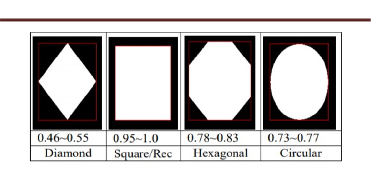
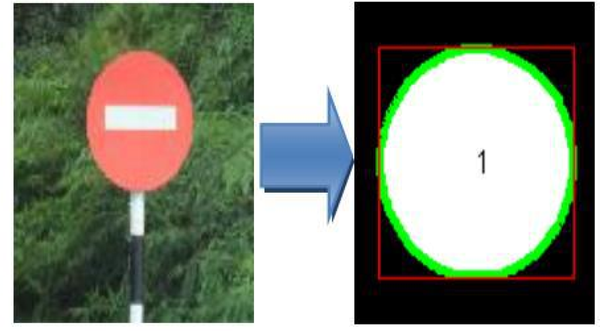
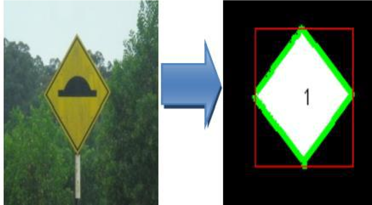
The above figures show the real signs that have been captured in a real environment which are identified as a circle and a diamond shape based on the extant value. The boundaries which represent the green lines show the binary shape and determine the shape detected. The red frame shows the bounding box produced on the smallest technology containing the shape region.
The binary “1” indicates that 1 object has been detected by the color segmentation phase.
Phase-3: Symbol Recognition:
From the shape classification process, we obtain the shape region and their boundary box. These are normalized into a fixed dimension of 180 x 180 pixels and these are prepared for the recognition process. The ranges of the area and perimeter ratios of different symbols are compared with the reference ratios of standard images.
Area Ratio = Area of Symbol Region / Area of Shape Region (7)
Peri Ratio = Area of Symbol Region / Area of Shape Region (8)
According to the template that was proposed in x, the measurements of extent are equal for all different scaling values(corresponds to the various distances between the observer and the road sign in the straight roads) and rotation methods(corresponds to the road sign in the corner and hilly roads)
PYTHON IDLE:
Python is a general-purpose programming language started by Guido van Rossum, which became very popular in a short time mainly because of its simplicity and code readability. It enables the programmer to express his ideas in fewer lines of code without reducing any readability. Compared to other languages like C/C++, Python is slower. But another important feature of Python is that it can be easily extended with C/C++. This feature helps us to write computationally intensive codes in C/C++ and create a Python wrapper for it so that we can use these wrappers as Python modules. This gives us two advantages: first, our code is as fast as original C/C++ code (since it is the actual C# code working in the background) and second, it is very easy to code in Python. This is how OpenCV-Python works, it is a Python wrapper around original C++ implementation and the support of Numpy makes the task easier.
Numpy:
It is a highly optimized library for numerical operations. It gives a MATLAB-style syntax. All the OpenCV array structures are converted to-und-from Numpy arrays. So whatever operations you can do in Numpy, you can combine it with OpenCV, which increases the number of weapons in your arsenal. Besides that, several other libraries like Scipy.
Matplotlib:
It is a Python 2D plotting library that produces publication quality figures in a variety of hardcopy formats and interactive environments across platforms. Matplotlib can be used in Python scripts, the Python and IPython shells, the Jupiter notebook, web application servers, and four graphical user interface toolkits. Matplotlib tries to make easy things easy and hard things possible. We can generate plots, histograms, power spectra, bar charts, or charts scatterplots, etc. Numpy is a library for Python programming adding support for arrays and along with a large collection of high-level mathematical functions to operate on these Cv2 (OpenCV) lot of supports and algorithms related to Computer Vision and Machine Learning expanding day-by-day. Currently, OpenCV supports a wide variety of programming Java, etc. They are available on different platforms including OS etc. Also, interfaces based on CUDA and OpenCL development for high-speed GPU operations. OpenCV-Python is the Python Other supporting need to install with essential checkinstall make pkg-config yasm. git Fortran. dev, libtiff-dev, libavcodec-dev libav libswscale-dev libgstreamer0.10- dev libgstreamer-plugins-base). libatlasbase-dev. libmp3lame-dev libopencore-ammbdevTime module provides various time-related functions. Like time. asctimeid). etc each syntax has its functionality. Most of the functions defined in this module call platform C library functions with the same name. It may sometimes be helpful to the semantics of these functions varies among platforms consult the platform because of the Argparse.
Command-line:
The program defines what arguments it an argparse will figure out to parse out of The argparse module also automatically generates help and usage messages and issues errors when users give the program invalid arguments .to make basic image processing functions such as convenience functions around Werkzeug and Jinja and has become one of the most popular Python web application Fisk offers suggestions, but does not enforce any dependencies or project layout. It is up to the developer to choose the tools and libraries they want to use. There are many extensions provided by the community that makes adding new functionality easy.
OpenCV (Open source computer vision) is a library of programming functions mainly aimed at real-time computer vision. Originally developed by Intel, it was later supported by Willow Garage then Itseez (which was later acquired by Intel). The library is cross-platform and free for use under the open-source BSD license.
OpenCV supports some models from deep learning frameworks like Tensor Flow, Torch, PyTorch (after converting to an ONNX model), and Caffe according to a defined list of supported layers. It promotes OpenVisionCapsules., which is a portable format, compatible with all other formats.
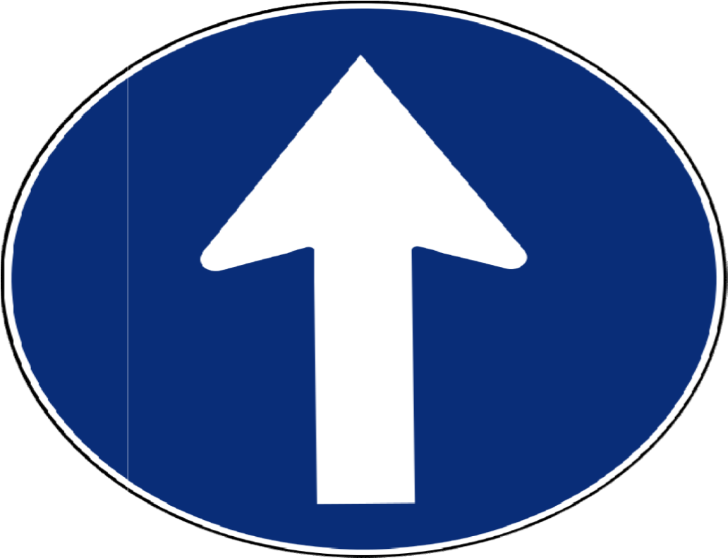
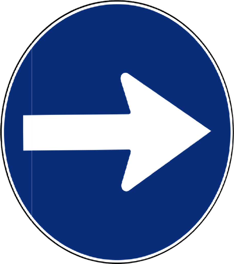
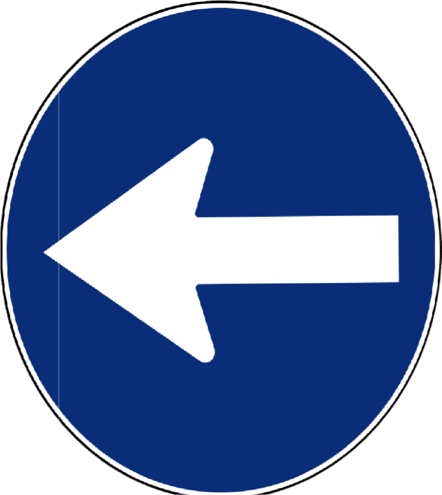
DIFFERENT TYPES OF SIGN BOARDS :

RESULTS:
- Figure shows that the detection left turn sign in Python Idle using raspberry pi.
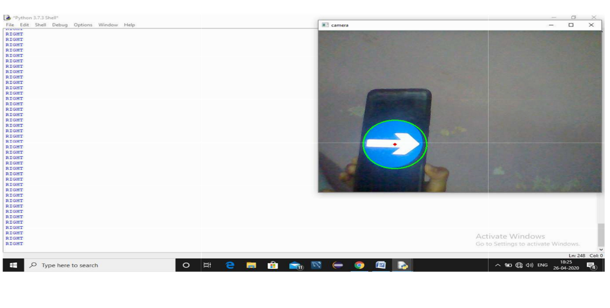
2. Figure shows that the detection of right turn sign in Python Idle using raspberry pi.
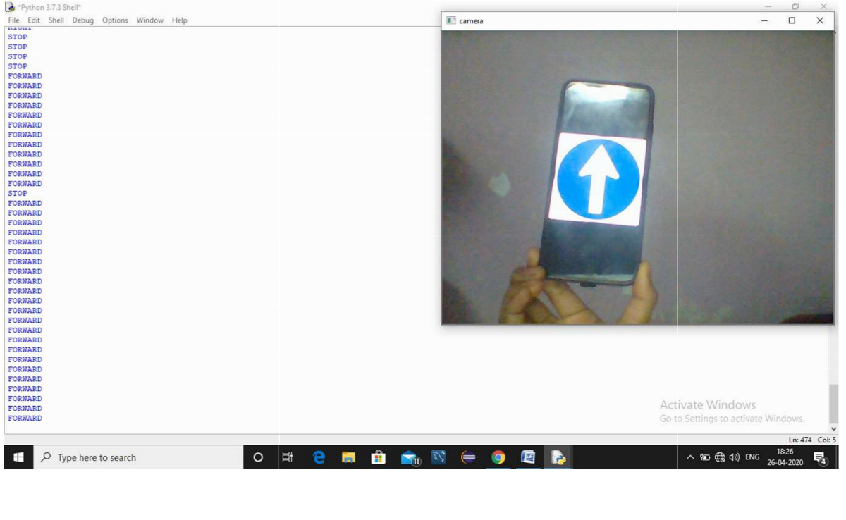
3. Figure shows that the forward sign detection in Python Idle using raspberry pi
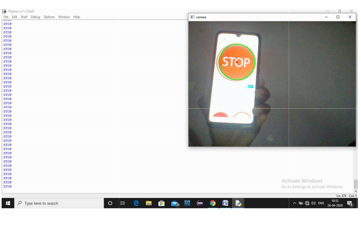
4. Figure shows that Stop sign detection in Python Idle using Raspberry Pi.
5. Figure shows the entire vehicle front view and road sign detection is used to predict the next movement and also vehicle movement is done by using the pie camera and web cam using raspberry pi.
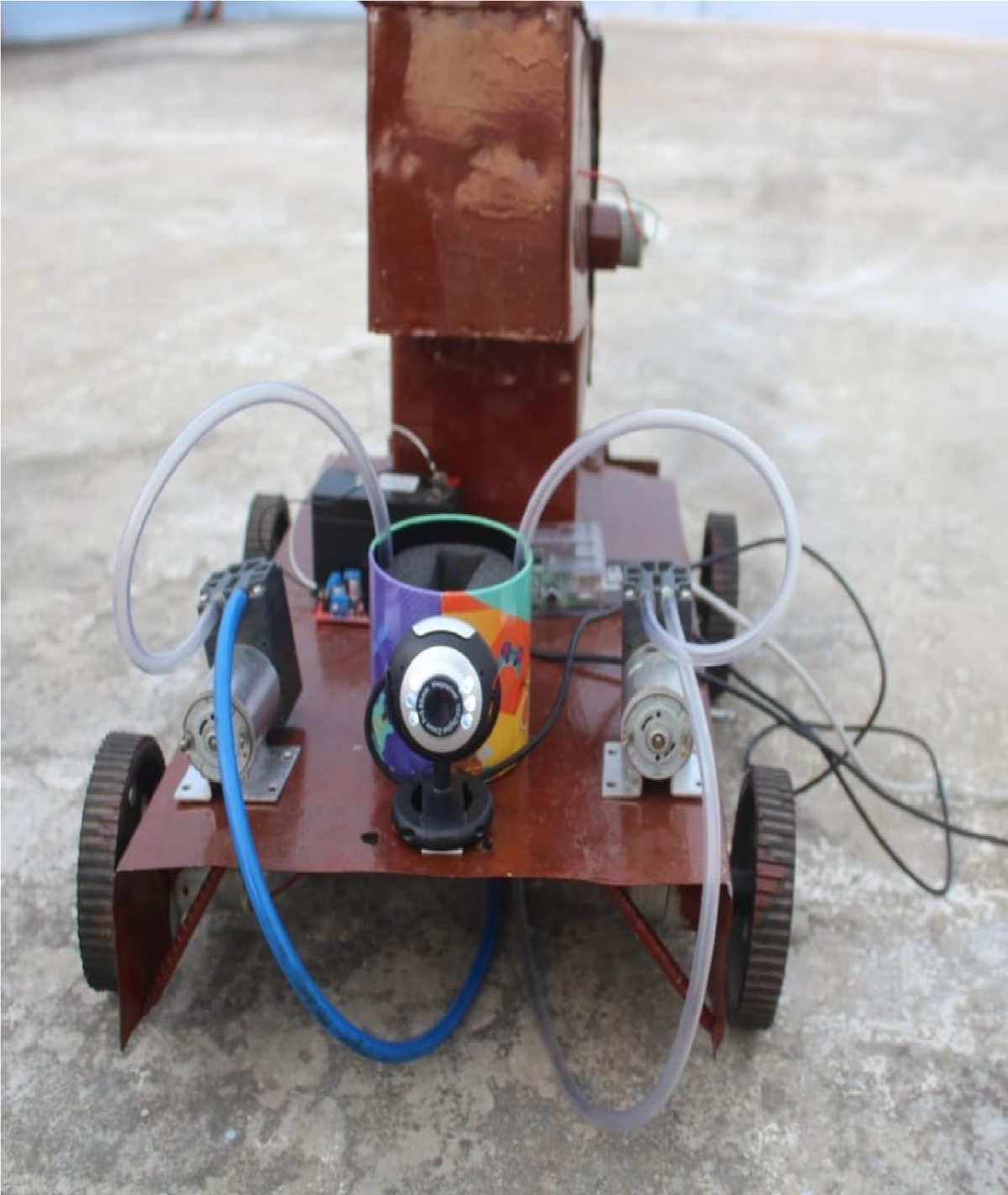
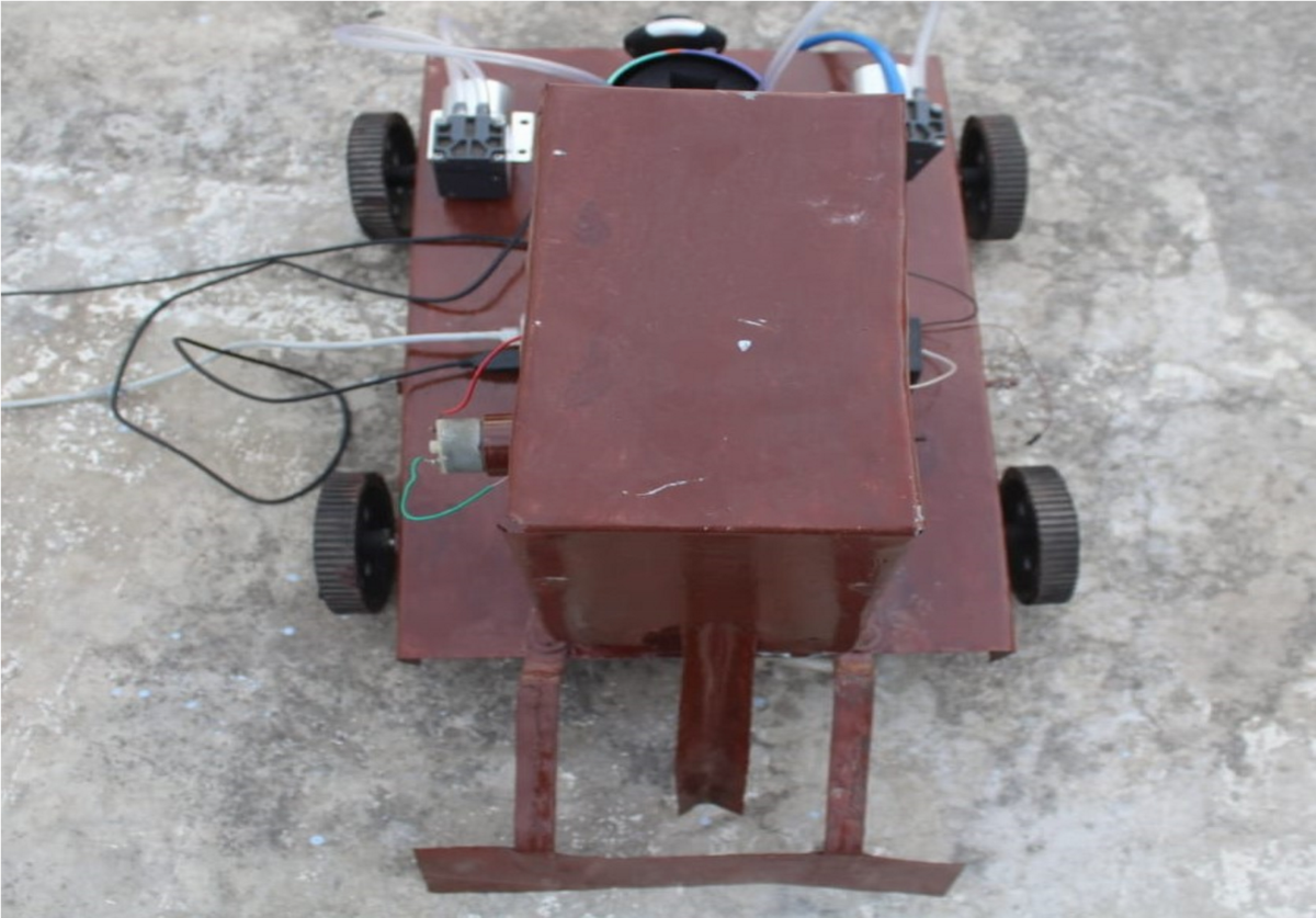
6. Figure shows that top view of the vehicle.
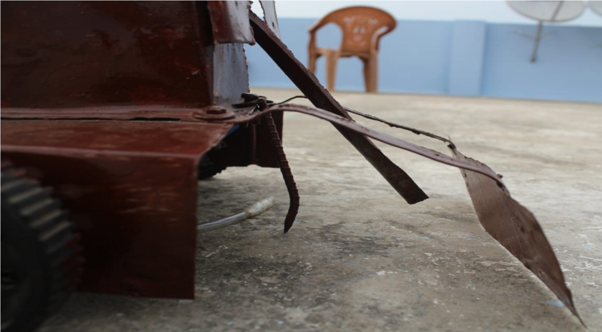
7. Figure shows the ploughing and covering stage.
8. Figure shows the water sprinkling mechanism of water and pesticides in the respective area.