
Why does this project exist?
I have been making mobile robots for a while now, but the one thing which is still not changed in my journey is the use of those slow yellow-colored BO Motors and their boring wheels. So, I wanted to change it and this is why I came up with the fastest, most compact, inexpensive, and 3D printed BO motors wheel which I think is an amazing upgrade for robots that will make hobbyist's robots go faster than ever before
STEP 1: Brief about the project
So, here is a video to show what’s inside the project. I have created this little animation for better understanding.
STEP 2: Grab all the components
Wait, wait, wait. You don’t need anything out of this world. If you are a maker and have been tinkering for a while now. You will find all of them in your arsenal, refer to the components section.
One thing that might not be available in your lab is a 3D printer. But nowadays, there are a lot of 3D printing services available that you can very easily access. Please refer to the attachments section for 3D files.
Step 3: 3D print the required parts
So, there are only 2 parts that are required to be 3D printed. The 1st part is the Hub of the motor and the other is the mount using which you can attach it to the chassis of your robot. I’m using a Prusa slicer to slice my models. It took 3 hours and 2 mins to print both the parts with 50% infill and 0.2mm layer height and I am using Ender 3 V2 to print the same.
If you are using a 3D printing service, you will just have to know about the infill which is 50% and layer height which is 0.2mm, the rest will be handled by the service provider.
.png)
Step 4: BLDC Motor Modification
Before we use the motor in our project, we have to modify it, and here is how we can do this step by step.
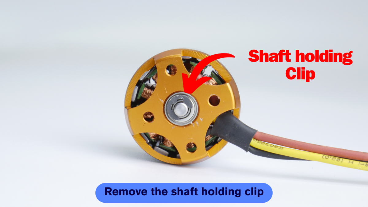
STEP A: REMOVE SHAFT HOLDING CLIP
Firstly, we have to remove the shaft holding clip which is used to keep the prevention the detachment of the top part when the propeller is attached to it due to thrust. Take a sharp object and pull it sideways. Without the removal of this clip, you won’t be able to separate the upper and lower half of the motor.
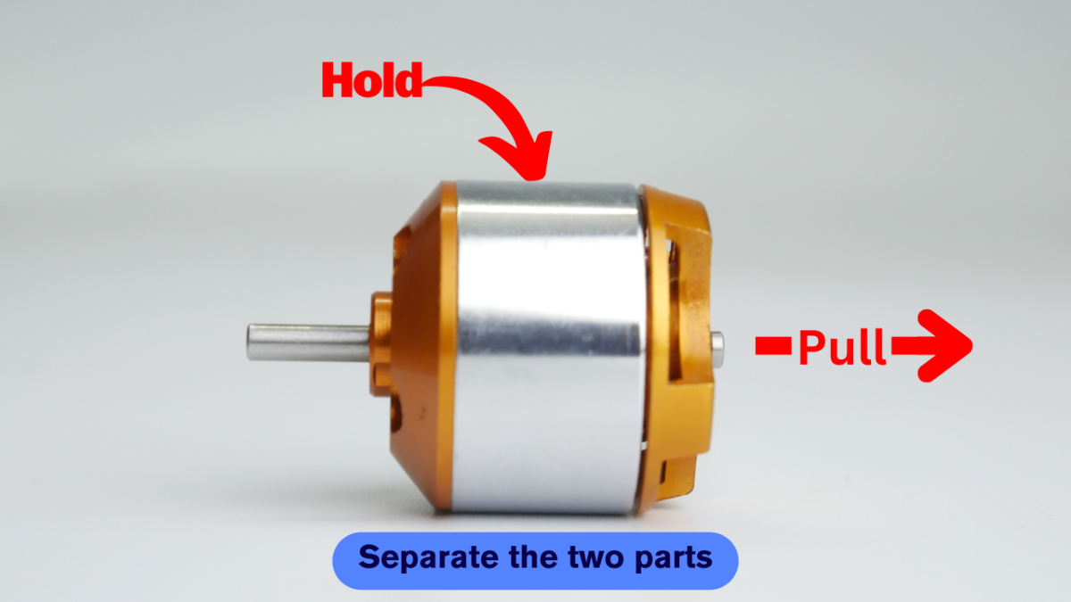
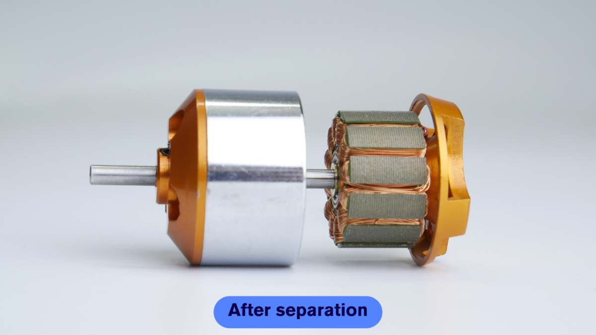
STEP B: SEPARATE UPPER AND LOWER PARTS
Now, you can easily pull the upper and lower half of the motor. Be careful while doing this because when you will try to pull the lower part out at the same time the magnets inside the motor will try to pull the lower part inwards as a result of which you may get harmed if your finger is in between the upper and lower part.
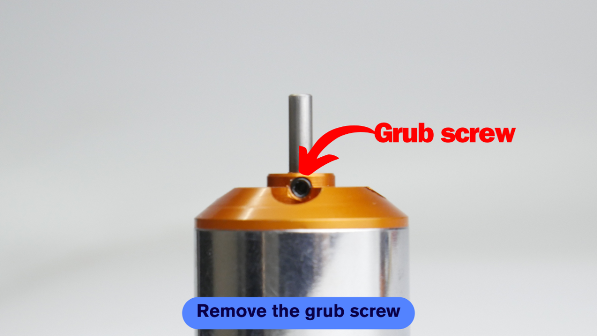
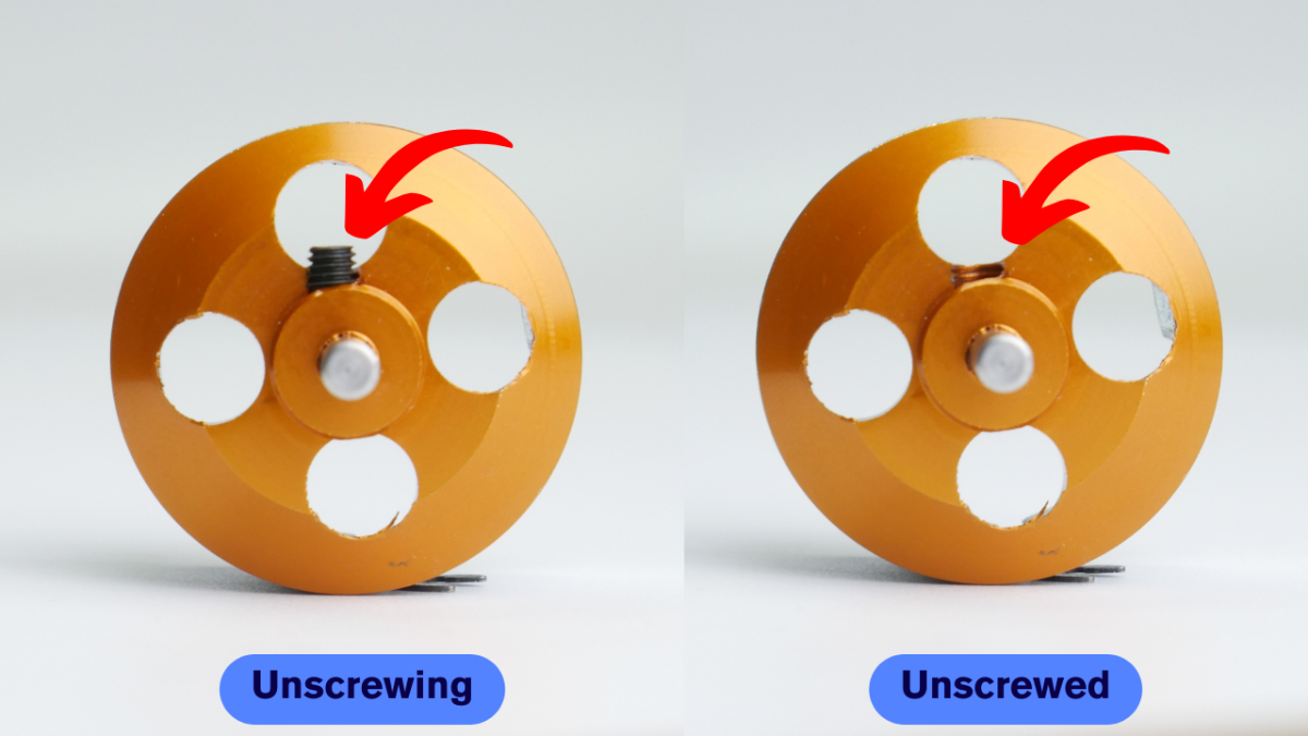
STEP C: GRUB SCEW REMOVAL
There is a grub screw that holds the shaft in place and prevents any dislocation of the shaft while working. We have to remove it because we have to adjust the height of the shaft.
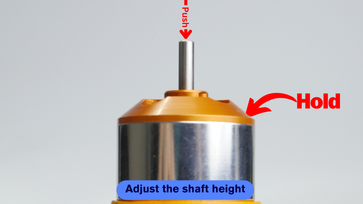
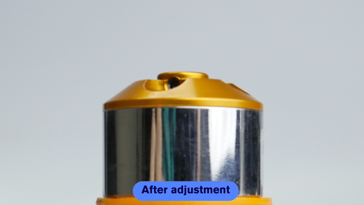
STEP D: SHAFT HEIGHT ADJUSTMENT
As the grub screw is now removed, you can place the upper part of the motor on a suitable surface so that the shaft can go down while pressing. You have to apply a lot of pressure here, I have used a hammer to do the same.
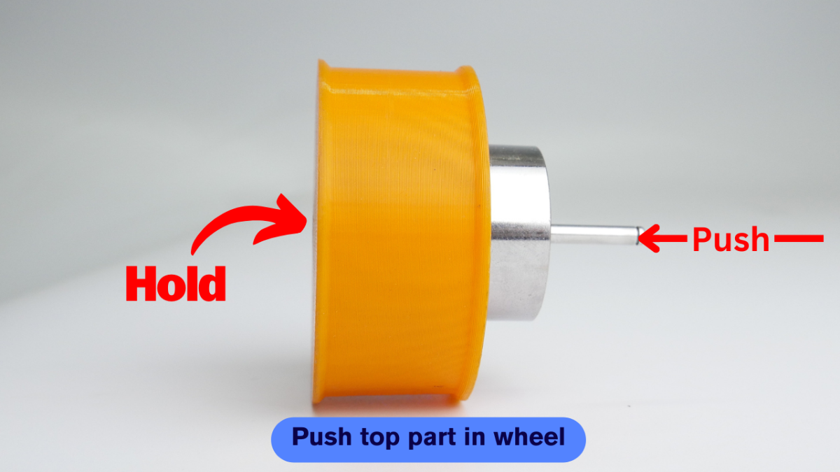
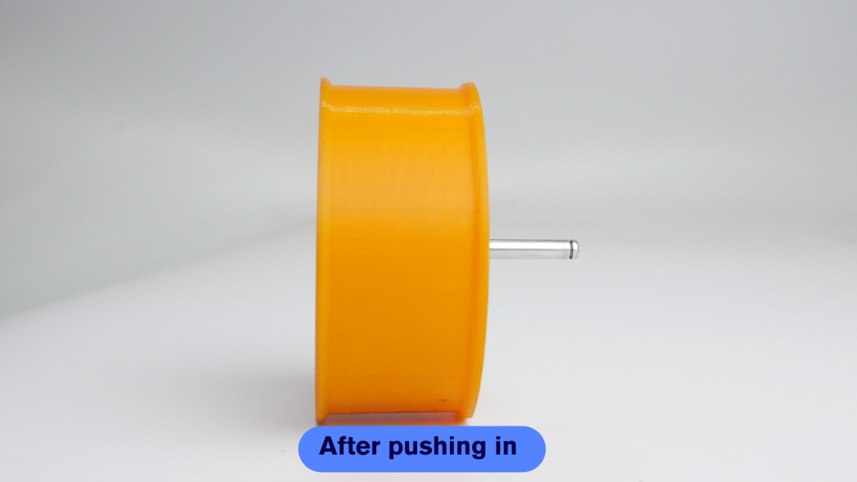
STEP E: ASSEMBLE 3D PRINTED HUB AND TOP PART OF MOTOR
The inner section of the motor will rotate at a very high speed as a result of which the 3D-printed part will not be able to move with it because we are not using any adhesive here. So, to make the 3D printed part move with the motor, I have added 4 support pins that will go inside the holes and help the 3D printed part move with the motor.
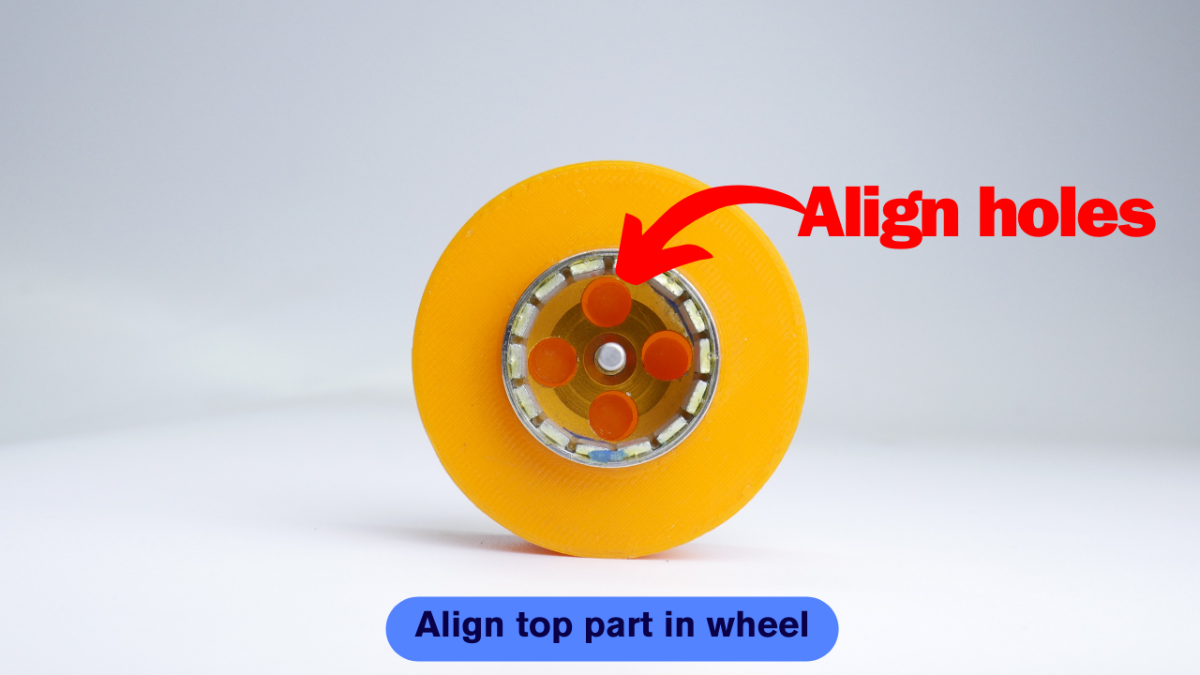
Once you have aligned the holes with the support pins, press the motor inside the 3D-printed part.
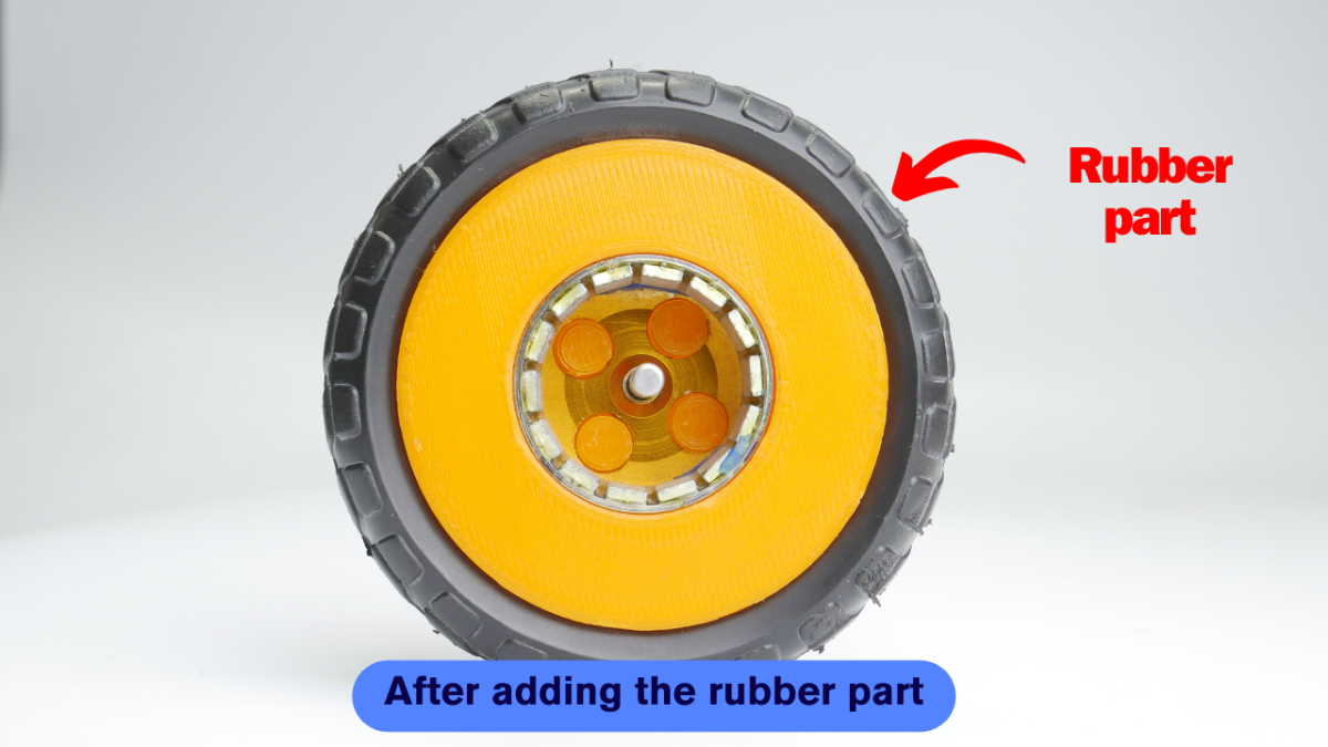
STEP F: ADD RUBBER PART OF BO MOTOR WHEEL
Now add the rubber part to the 3D printed part. I have removed the rubber part from an inexpensive BO Motor wheel which saves my designing and printing time.
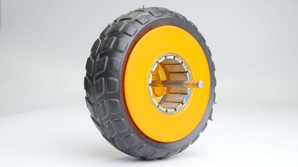
STEP G: ASSEMBLE BOTTOM PART OF MOTOR AND 3D PRINTED MOUNT
Notice the distance between the holes which are opposite to each other. One set of holes has a shorter distance as compared to the other set. And we will be using this set with a shorter distance to connect our 3D-printed mount.
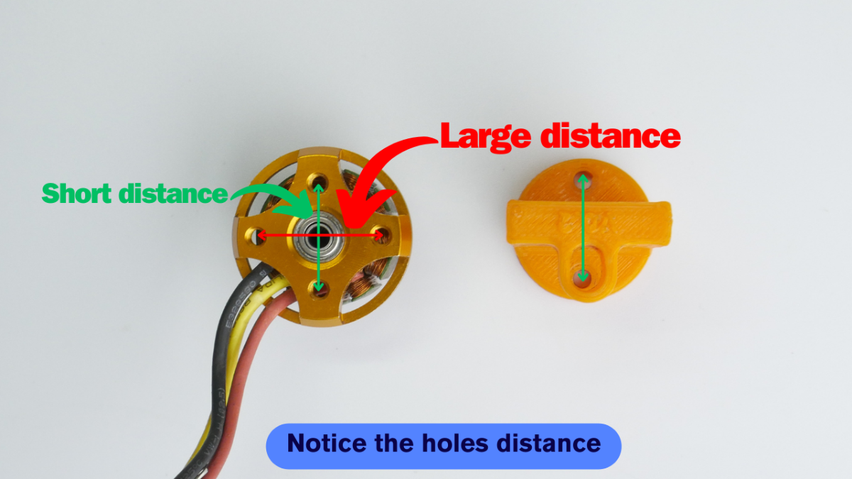
Place the 3D printed mount as mentioned above and add the screw that came with the motor.
.png)
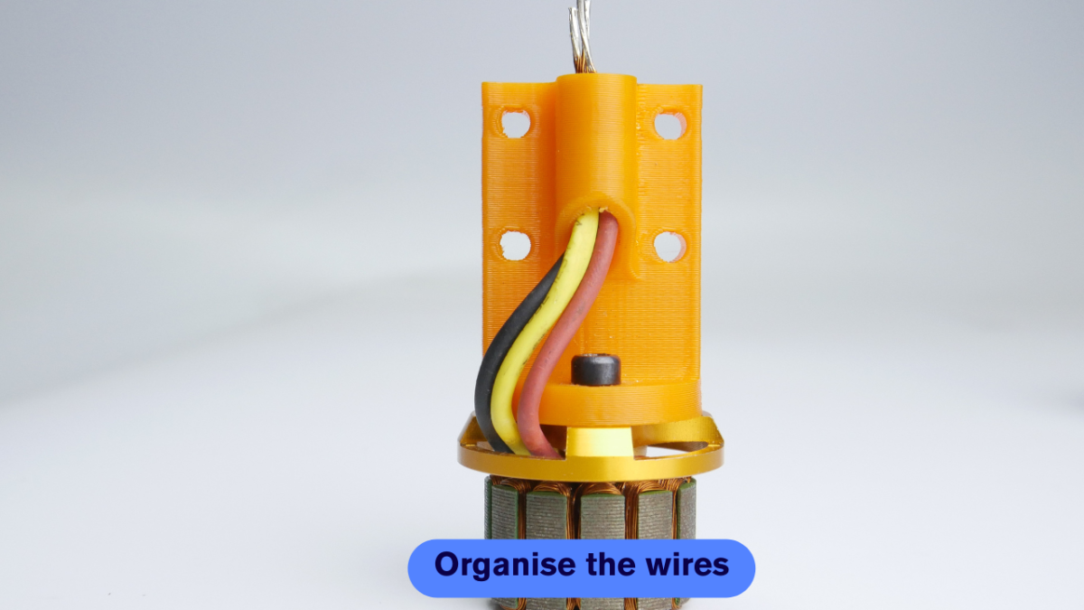
To avoid tangling of wires, pass the wires through a hole as shown in the image.
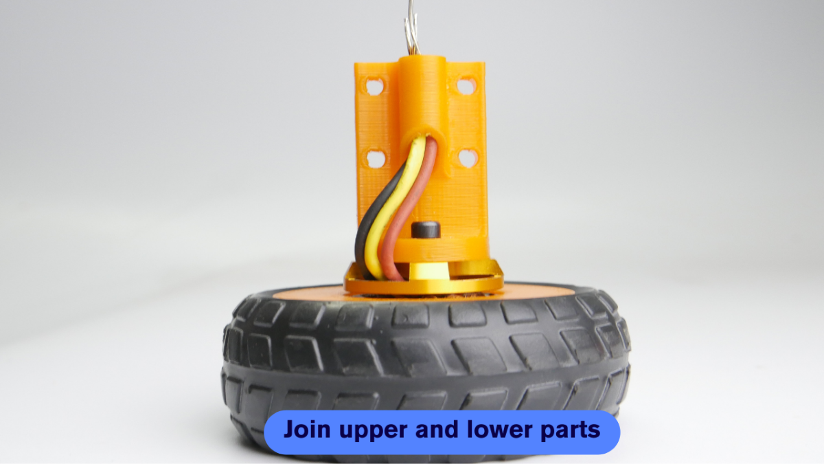
STEP H: COMPLETE THE ASSEMBLY
This is the final assembly step, join the upper and lower half and your wheel is now ready to rock on.
This is how my test setup looks. Simple and elegant.✨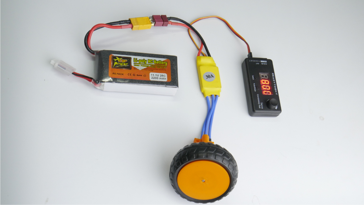
WORKING OF PROJECT:
Time to answer some questions:
Q: Does this project solve the social problems?
Yes, it does. How? At present innovation in robotics is happening at a very high pace but all that innovation is happening at just higher levels where millions of dollars are invested. But when it comes to makers or hobbyists, we are still stuck with decades-old tech, how will beginners be able to think something new with decades-old tech? So, using the latest technology, I made this innovative hub motor that anyone can make and use in their projects very easily with detailed steps.
Q: Is there a depth of design detail available?
Yes, it's available. I explained each step with self-explainable images along with 3D models and videos as well.
Q: Can the project develop into an entrepreneurship program?
Yes, with some support and funding, I will be able to improve the design, performance, and efficiency of the project. For this prototype, I have used PLA+ material will is quite inexpensive and is also not so strong. I want to try out other different types of materials and have been working on a multi-material version of the same, that will simplify the assembly process even more and provide even more strength and functionality as well.
Q: Does the project have the possibility of productization?
Yes, I think a project that can't be reached to the masses will make any sense. So, a big yes, will some more testing and R&D(which I am still doing), it can be converted into a product and that is my goal to make it available to all the robotics enthusiasts in the World.
Q: Is the technology used efficient, and cost-effective?
Yes, from the beginning of this project, cost-effectiveness and productization were the two key points I kept in mind. That's why the project is designed in such a way that it can be 3D printed without any support material which will save us time (printing time and post-processing time) as well as money (which might get wasted in support material). The cost of the complete project is under INR 800 or $10 which includes 3D printed parts, BLDC Motor, and ESC. We can even drop it down when it is manufactured in bulk because then, only I will get the BLDC motor and ESC at much cheaper prices from the vendors.
Q: How will it be helpful for humanity?
This is not just a wheel for robots that is to be used by hobbyists only. The goal of building this project is to integrate it into emergency robots so that they can reach destinations at a much faster pace and save lives. By making it available for hobbyists, I am opening doors for more and more innovative robots that can help humanity and make this world a better place.