Project Description
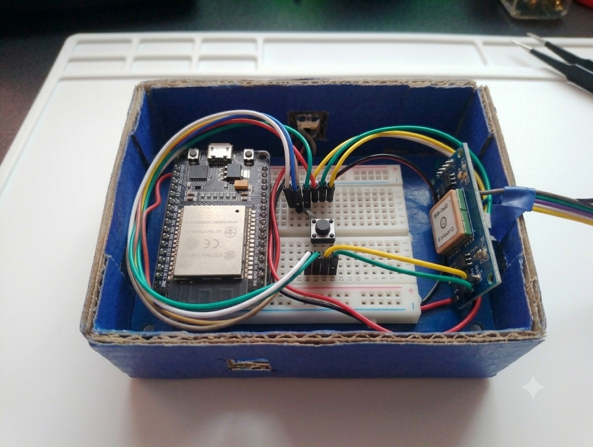
The Smart Safety Device is an IoT-based emergency alert system designed to provide immediate assistance during emergencies. The project uses an ESP32 microcontroller, Neo-6M GPS module, and an SOS push button. When the SOS button is pressed, the ESP32 reads the user's current GPS location and sends an emergency alert message along with a Google Maps location link to a Telegram bot. This enables family members, friends, or emergency responders to quickly locate and assist the user.
Components Required
| Component | Quantity |
|---|---|
| ESP32 Development Board | 1 |
| Neo-6M GPS Module | 1 |
| Push Button | 1 |
| Breadboard | 1 |
| Jumper Wires | As Required |
| USB Cable | 1 |
| Wi-Fi Connection | 1 |
| Telegram Bot | 1 |
Step 1: Prepare the Components
Gather all the required components:
- ESP32 Development Board
- Neo-6M GPS Module
- Push Button
- Breadboard
- Jumper Wires
- USB Cable
Step 2: Connect the GPS Module
Make the following connections:
| Neo-6M GPS | ESP32 |
|---|---|
| VCC | 3.3V |
| GND | GND |
| TX | GPIO16 (RX2) |
| RX | GPIO17 (TX2) |
The GPS module will continuously receive satellite data and provide location coordinates.
Step 3: Connect the SOS Push Button
Connect the push button as follows:
| Push Button | ESP32 |
|---|---|
| One Terminal | GPIO4 |
| Other Terminal | GND |
When pressed, the button triggers the emergency alert process.
Step 4: Create Telegram Bot
- Open Telegram.
- Search for BotFather.
- Type
/newbot. - Enter bot name and username.
- Copy the generated Bot Token.
- Obtain your Chat ID.
- Add both values to the ESP32 program.
Step 5: Program the ESP32
- Install Arduino IDE.
- Install ESP32 Board Package.
- Install required libraries:
- TinyGPS++
- WiFi
- UniversalTelegramBot
- Upload the program to ESP32.
After uploading, the ESP32 connects to Wi-Fi and starts receiving GPS data.
code--
#include <WiFi.h>
#include <WiFiClientSecure.h>
#include <UniversalTelegramBot.h>
#include <TinyGPS++.h>
//  WiFi Credentials
const char* ssid = "wifiname";
const char* password = "password ";
//  Telegram Bot
#define BOTtoken "8770187114:AAGG2HxTHQuI5-5-gXVweLT1VIQfoF5t12I"
#define CHAT_ID "7098141457"
WiFiClientSecure client;
UniversalTelegramBot bot(BOTtoken, client);
//  GPS Setup
TinyGPSPlus gps;
HardwareSerial gpsSerial(1);
//  Pins
#define GPS_RX 16   // ESP32 RX ← GPS TX
#define GPS_TX 17   // ESP32 TX → GPS RX
int buttonPin = 4;
void setup() {
 Serial.begin(115200);
 // Button
 pinMode(buttonPin, INPUT_PULLUP);
 // GPS Serial
 gpsSerial.begin(9600, SERIAL_8N1, GPS_RX, GPS_TX);
 // WiFi
 WiFi.begin(ssid, password);
 Serial.print("Connecting to WiFi");
 while (WiFi.status() != WL_CONNECTED) {
   delay(500);
   Serial.print(".");
 }
 Serial.println("\nConnected to WiFi");
 client.setInsecure(); // HTTPS
}
void loop() {
 //  Read GPS Data continuously
 while (gpsSerial.available() > 0) {
   gps.encode(gpsSerial.read());
 }
 //  Button Press
 if (digitalRead(buttonPin) == LOW) {
   Serial.println("Button Pressed!");
   if (gps.location.isValid()) {
     float lat = gps.location.lat();
     float lng = gps.location.lng();
     String message = " EMERGENCY ALERT!\n";
     message += "Live Location:\n";
     message += "https://maps.google.com/?q=";
     message += String(lat, 6);
     message += ",";
     message += String(lng, 6);
     bot.sendMessage(CHAT_ID, message, "");
     Serial.println("Location Sent!");
   }
   else {
     Serial.println("GPS not fixed yet!");
     bot.sendMessage(CHAT_ID, "⚠️ GPS not fixed. Try again.", "");
   }
   delay(5000); // avoid multiple sends
 }
}
Step 6: Testing the Device
- Power ON the device.
- Wait for GPS signal lock.
- Press the SOS button.
- ESP32 reads latitude and longitude.
- Telegram receives:
- Emergency Alert Message
- GPS Coordinates
- Google Maps Location Link
Working of the Project
The ESP32 continuously remains connected to a Wi-Fi network and receives real-time location data from the Neo-6M GPS module. The device stays in standby mode until the SOS push button is pressed. Once the button is pressed, the ESP32 fetches the current latitude and longitude coordinates from the GPS module and generates a Google Maps location link.
The ESP32 then sends an emergency alert message along with the user's live location to a Telegram bot through the internet. The recipient instantly receives the notification and can view the exact location on Google Maps, enabling quick response and assistance during emergencies.
video of project-