The air we breathe indoors can often contain dust, pollutants, allergens, and microscopic particles that go unnoticed but can affect our health over time. While commercial air purifiers are becoming increasingly common, they are often expensive, difficult to customize, and provide little insight into the quality of the air around us.
To address this, I created AirSense—a smart DIY air purifier that combines air purification, environmental monitoring, and cloud connectivity into a single intelligent system. Rather than simply filtering air, AirSense continuously measures indoor air quality and provides real-time information about the environment, helping users better understand and improve the air they breathe.
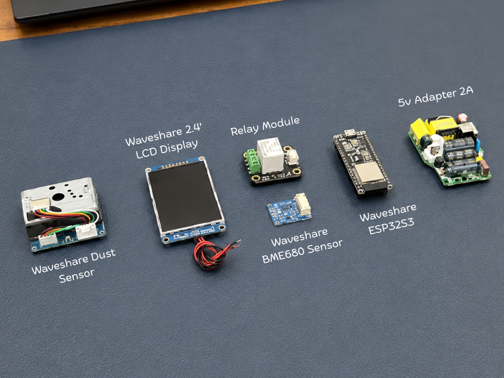
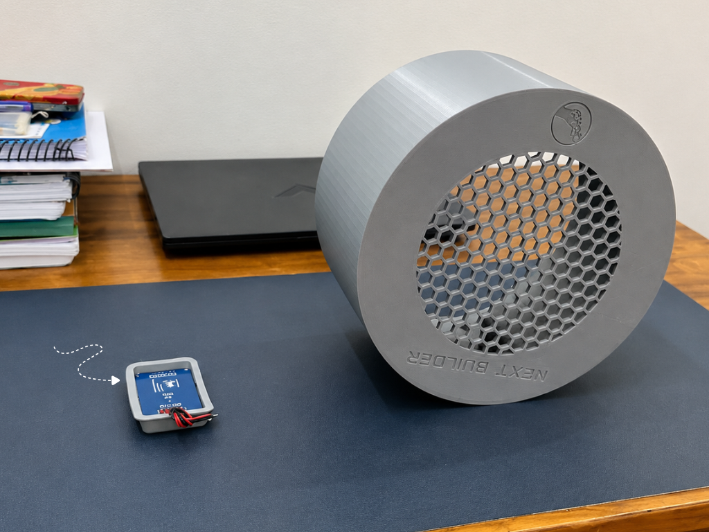
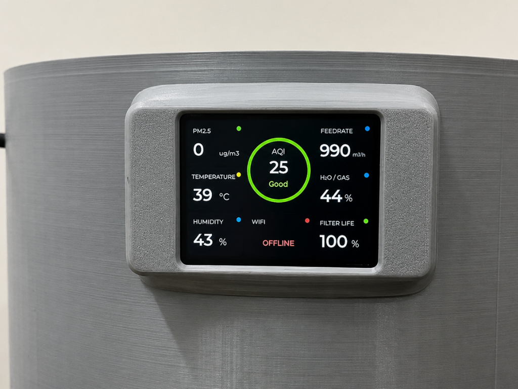
Built around the Waveshare ESP32-S3, the system monitors PM2.5 dust concentration, Air Quality Index (AQI), temperature, humidity, atmospheric pressure, and indoor air quality using dedicated environmental sensors. All collected data is displayed locally on a front-mounted LCD dashboard and can also be accessed remotely through Arduino IoT Cloud, allowing users to monitor their environment and control the purifier from anywhere using a smartphone.
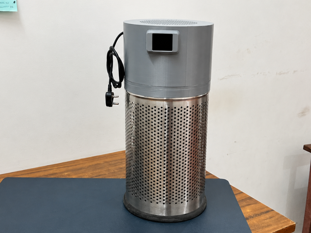
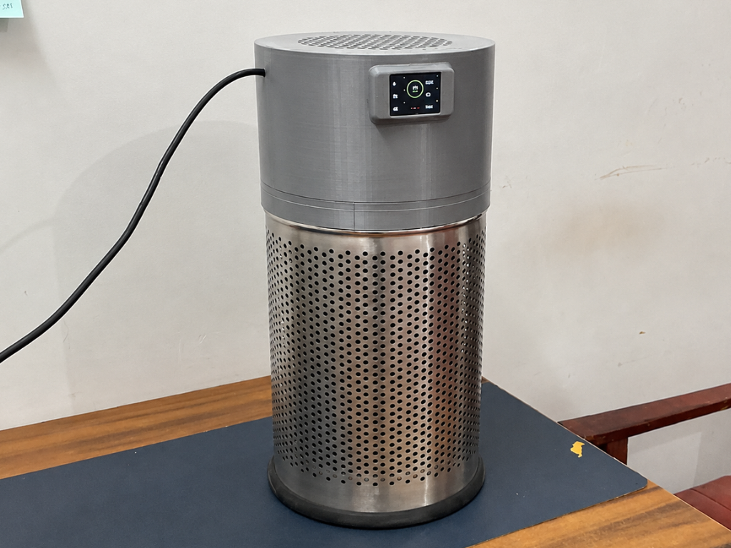
At the core of AirSense is a Xiaomi Air Purifier 4 Lite HEPA filter, capable of capturing up to 99.97% of airborne particles as small as 0.3 μm, including dust, pollen, smoke particles, and other common airborne contaminants. Combined with a powerful 150 mm exhaust fan, the system continuously pulls air through the 360° cylindrical filter, helping deliver cleaner and healthier air while providing complete visibility into the surrounding environment.
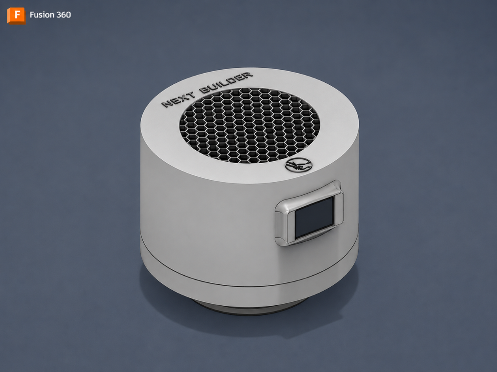
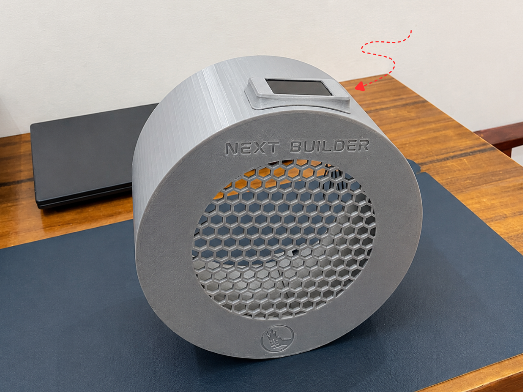
To give the project a professional product-like appearance, I designed the entire enclosure in Autodesk Fusion 360. The system integrates the HEPA filter, fan, sensors, display, and electronics into a compact custom housing that balances functionality, aesthetics, and ease of assembly.
AirSense is more than a DIY project—it is an example of how makers can build intelligent products that solve real-world problems and make technology accessible to everyone.
AirSense transforms ordinary air purification into an intelligent, connected experience—helping people breathe cleaner, healthier air every day.
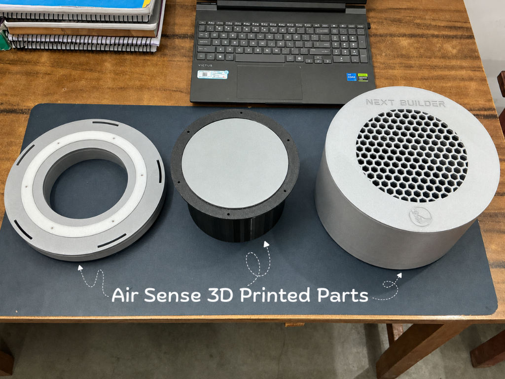
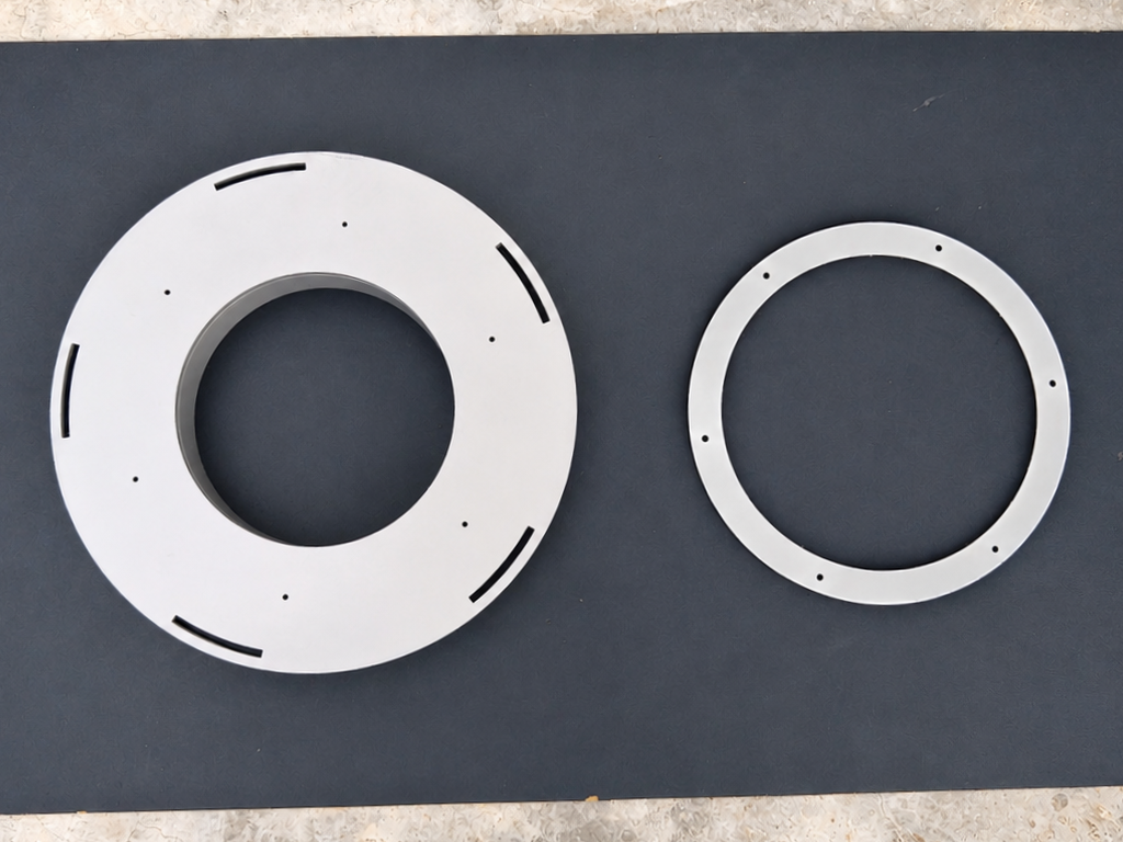
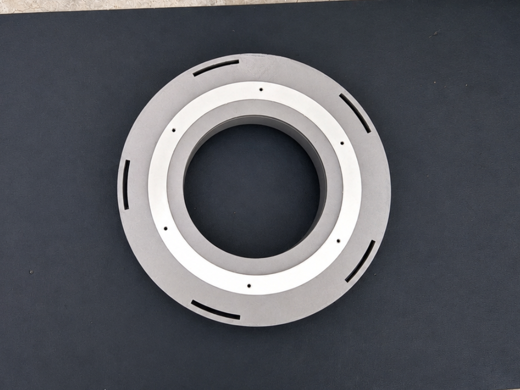
Step 1: CAD & 3D Printing
.png)
.png)
.png)
.png)
First Started by designing the enclosure in Autodesk Fusion 360. My goal was to create a design that was simple, compact, and easy to assemble while maintaining a clean, modern, and product-like appearance.
The enclosure was carefully designed to accommodate all the major components, including the HEPA filter, ventilation fan, sensors, display, and electronics, while ensuring proper airflow throughout the system.
If you'd like to explore the design in more detail, you can view the model directly in your browser using the Fusion 360 Web Viewer. The design files are also available for download below.
Files
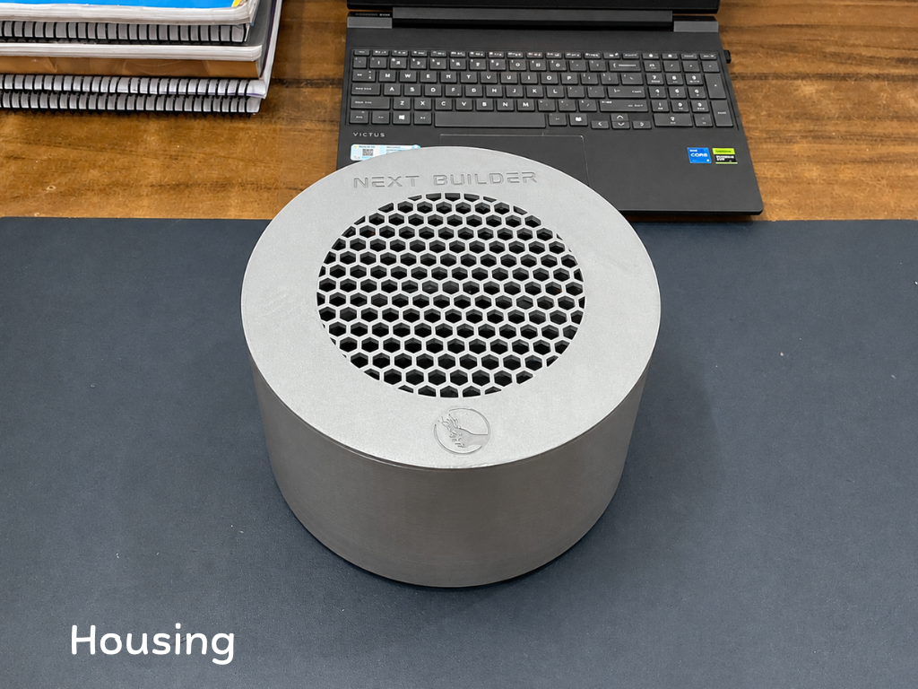
- Housing
- Motor Mount
- Filter Base
- Bottom Plate
- TPU Gasket
- Display Cover
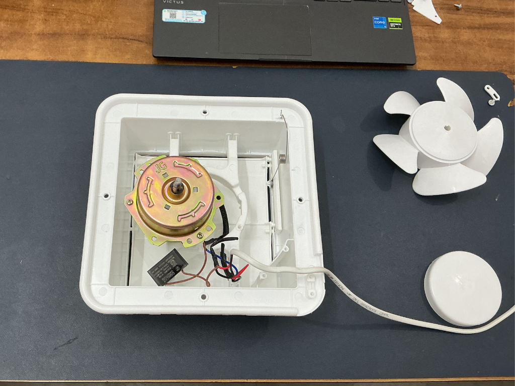
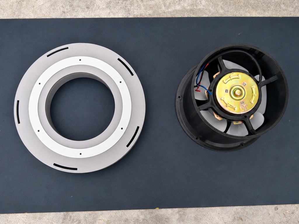
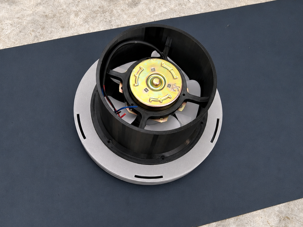
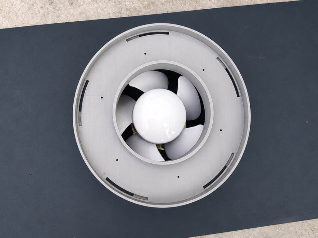
Step 2: Disassemble the Exhaust Fan
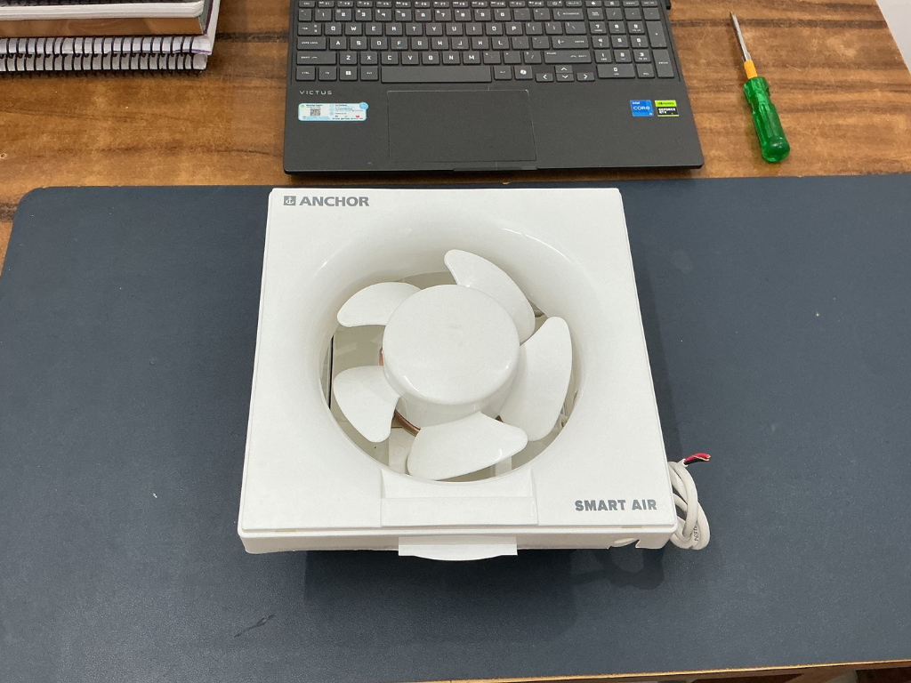
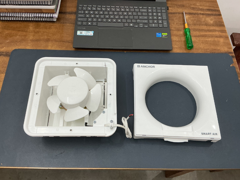
To begin the assembly process, we first need to disassemble the 150 mm Anchor Smart Air exhaust fan and remove the parts that are not required.
Start by removing the front cover of the fan. Next, carefully remove the center cap and fan blade to expose the motor assembly inside.
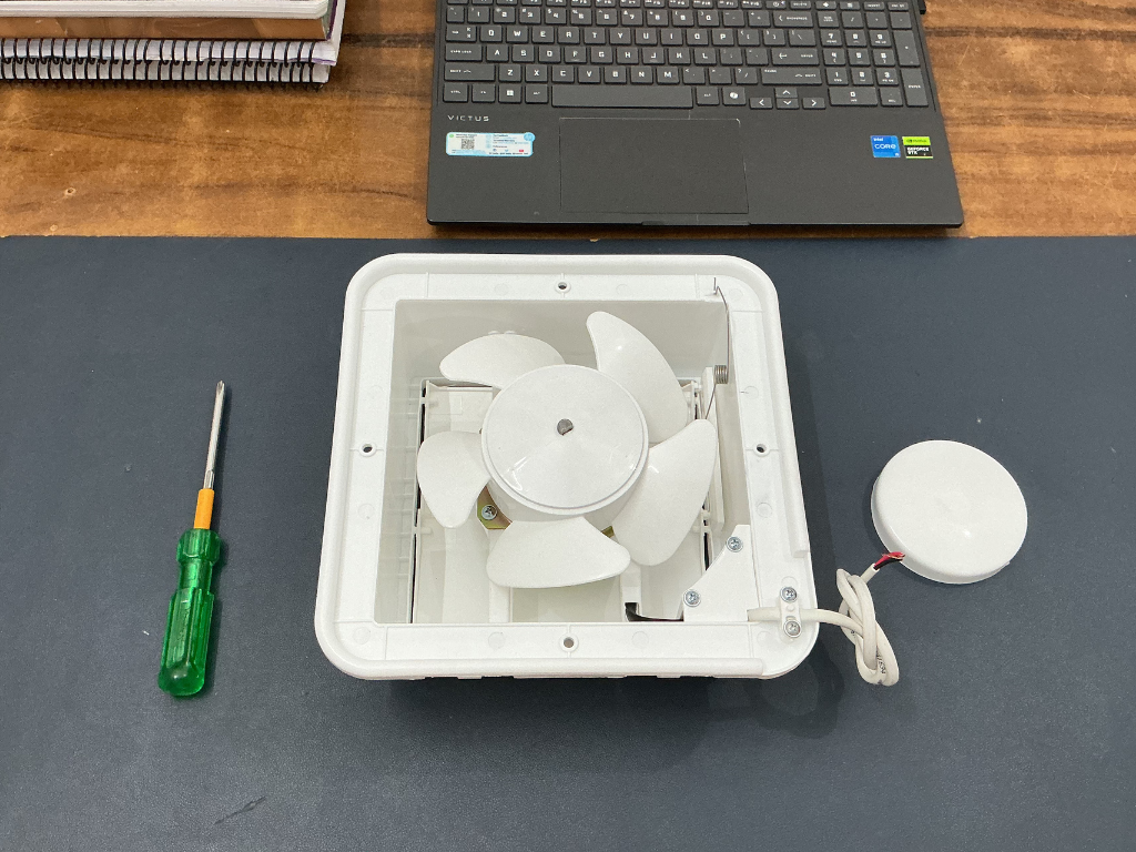
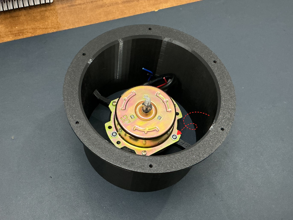
Step 3: Remove the Motor
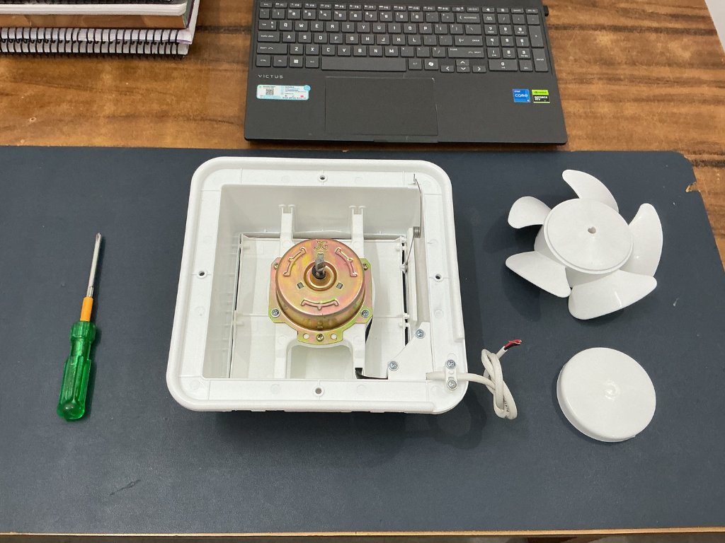
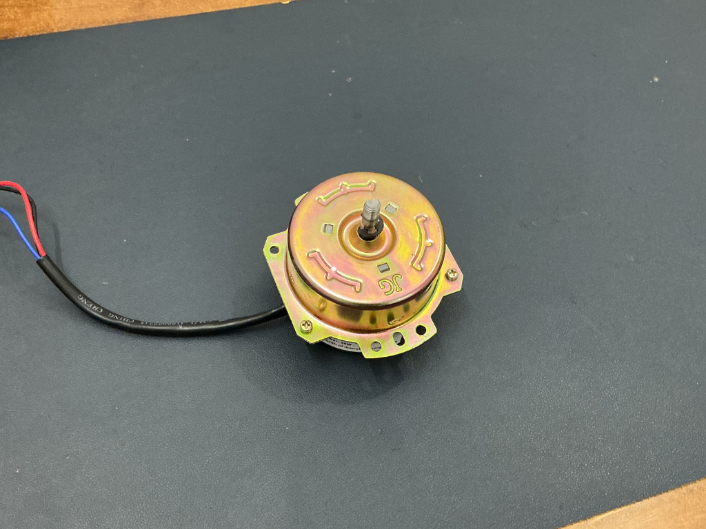
Start by unscrewing the motor from the fan housing. Once the mounting screws are removed, carefully disconnect the wires and lift the motor out of the frame.
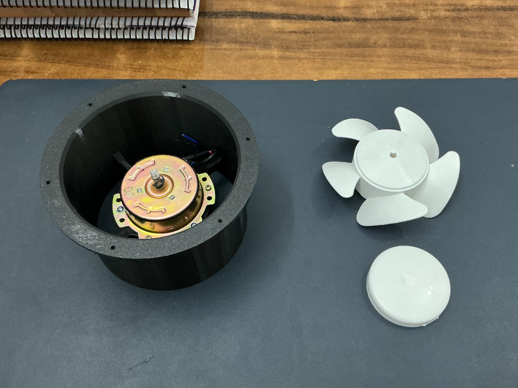
Since the original fan housing is no longer needed, it can be set aside. For this project, we only need the motor nad the fan blade, as it will be installed into the custom 3D-printed motor mount designed for AirSense.
Step 4: Assemble the Motor Mount
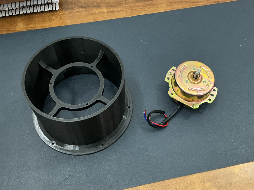
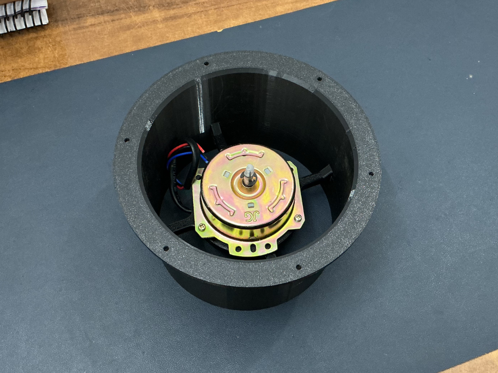
Now it's time to install the motor into the 3D-printed motor mount. Start by placing the motor inside the motor mount and aligning the mounting holes with the supports provided in the printed part. Once aligned, secure the motor using the appropriate screws.
Step 5: Install the Fan Blade
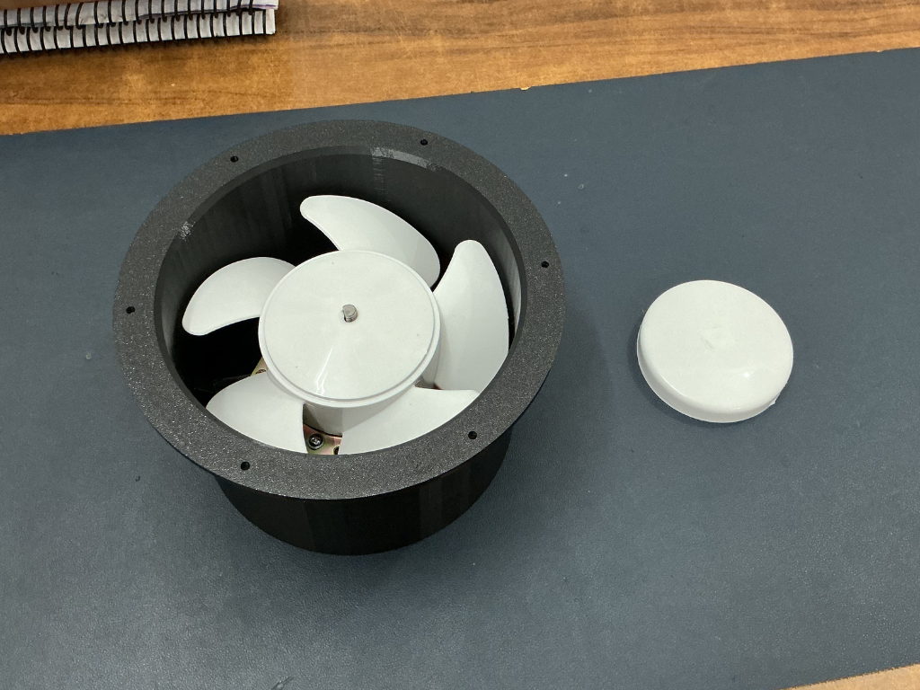
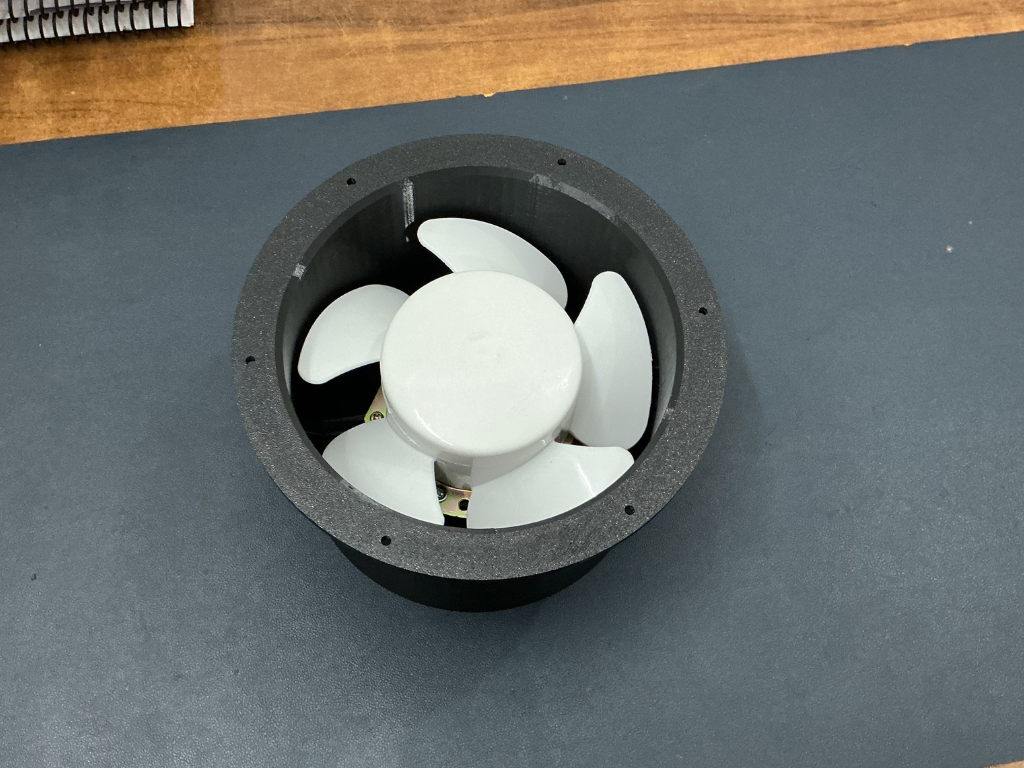
Carefully slide the fan blade onto the motor shaft and ensure it is seated properly. Once the blade is in place, attach the center cap to secure it.
After installation, rotate the blade by hand to make sure it spins freely and does not rub against the motor mount or enclosure. This quick check helps ensure smooth operation once the fan is powered.
Step 6: Install the TPU Gasket
Next, place the TPU gasket onto the bottom plate. Align the mounting holes on the gasket with the corresponding holes on the bottom plate and ensure it sits flat against the surface. The gasket helps create a tight seal between the filter and the enclosure, reducing air leakage and improving the overall filtration efficiency.
Step 7: Attach the Bottom Plate
With the motor assembly and bottom plate prepared, it's time to join them together. Place the motor mount onto the bottom plate, making sure all mounting holes are properly aligned. Once everything is positioned correctly, insert the M3 screws through the holes and tighten them evenly.
Make sure the assembly sits flat and secure without any gaps. The TPU gasket should remain properly aligned between the parts to maintain a good seal.
After tightening all the screws, give the assembly a quick inspection to ensure everything is firmly attached and the fan blade can still rotate freely.
Step 8: Attach the Filter Base
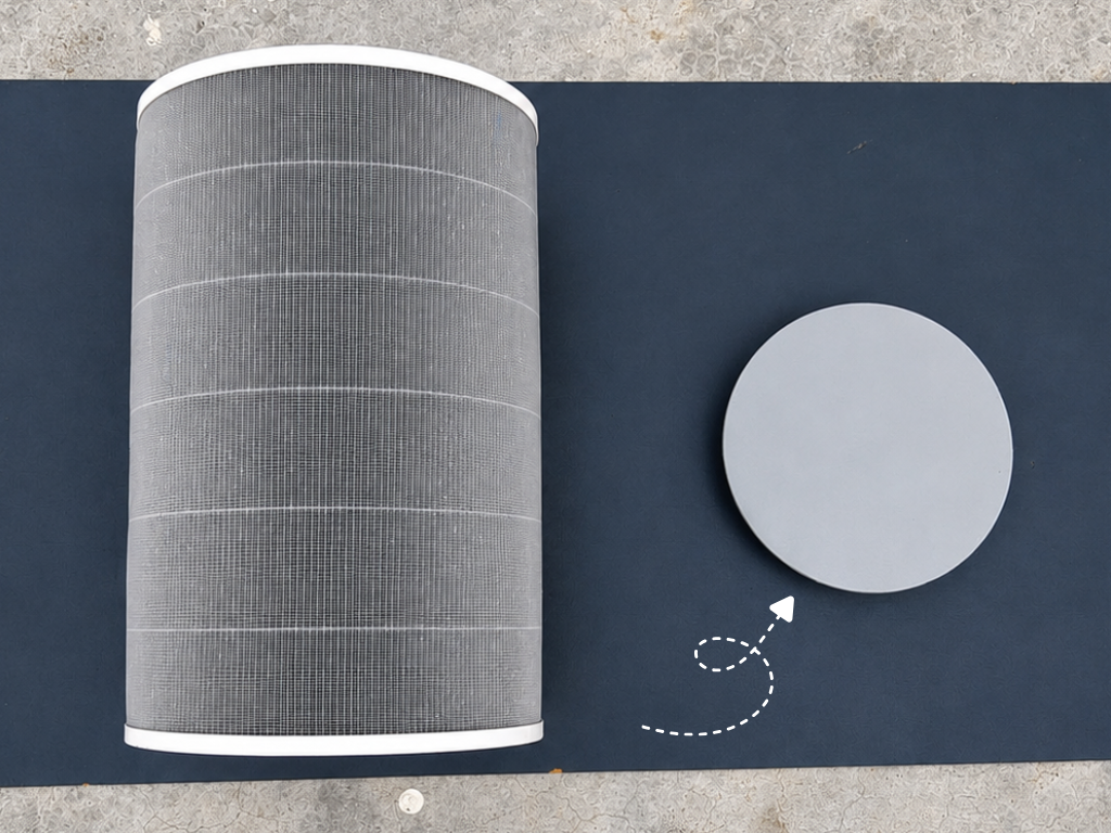
To support the filter and provide a mounting surface for the main assembly, attach the 3D-printed base to the back side of the HEPA filter.
Apply a small amount of super glue around the contact area of the printed base, then carefully position it on the filter. Make sure it is centered and properly aligned before the glue sets. Only a minimal amount of adhesive is required. Excess glue is unnecessary and may seep into unwanted areas.
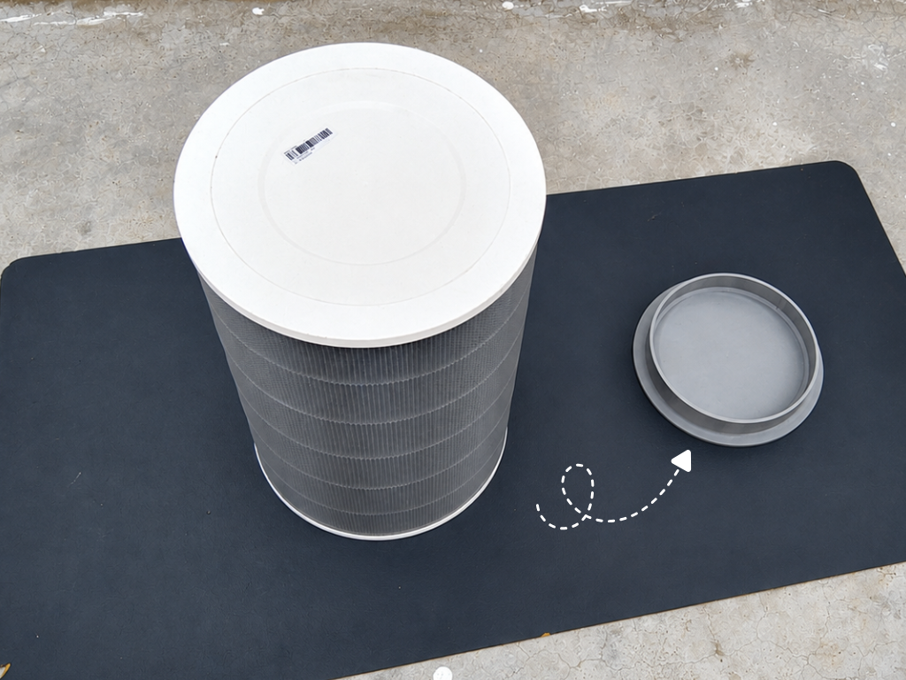
Step 9: Install the Filter Inside the Dustbin
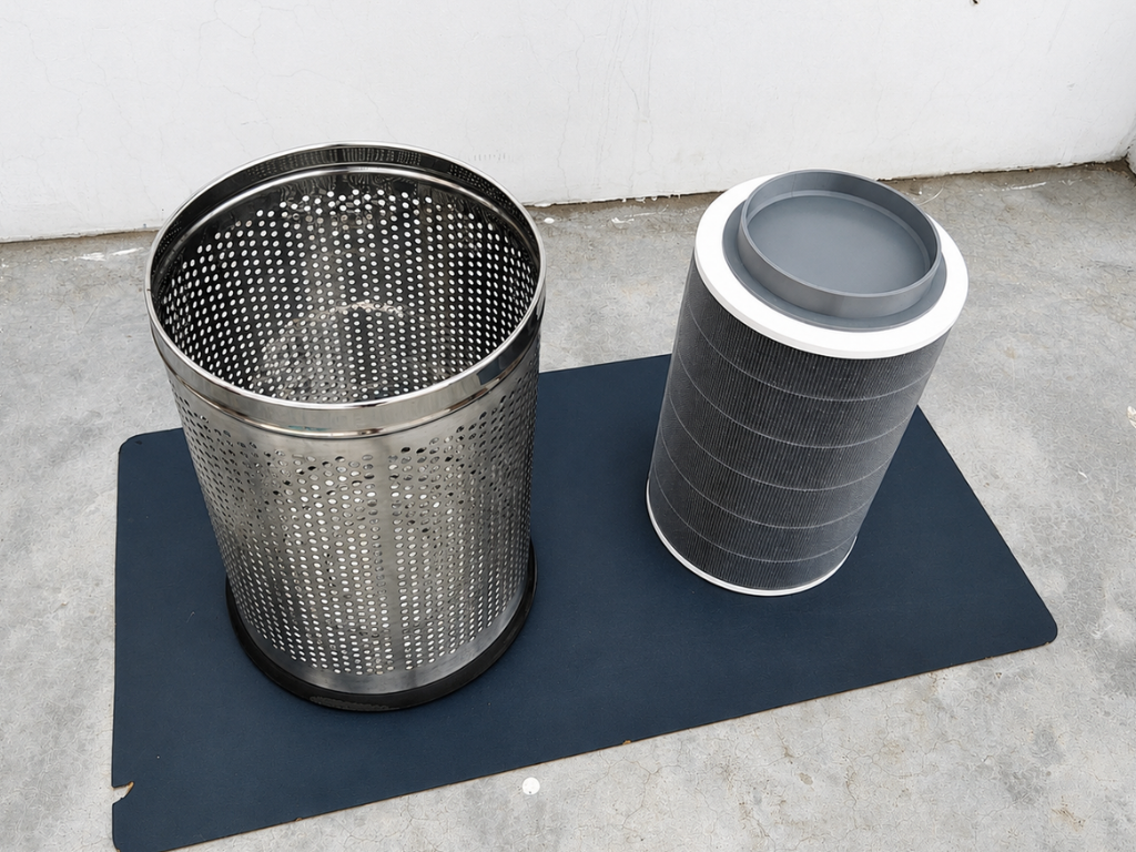
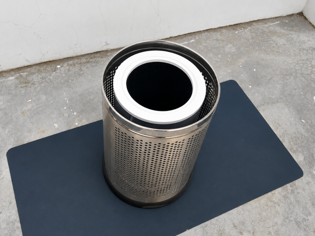
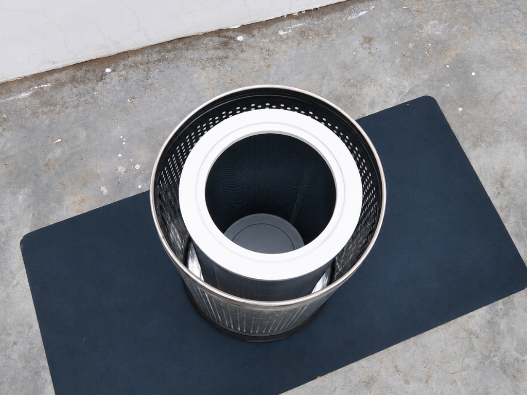
With the filter assembly complete, the next step is to install it inside the stainless-steel dustbin that serves as the main enclosure for AirSense.
Carefully lower the HEPA filter into the dustbin and position it in the center. The 3D-printed base should help keep the filter properly aligned and stable inside the enclosure.
Take a moment to ensure the filter sits straight and does not interfere with the walls of the dustbin. A properly aligned filter will help maintain good airflow and simplify the remaining assembly steps.
Step 10: The Power Adapter
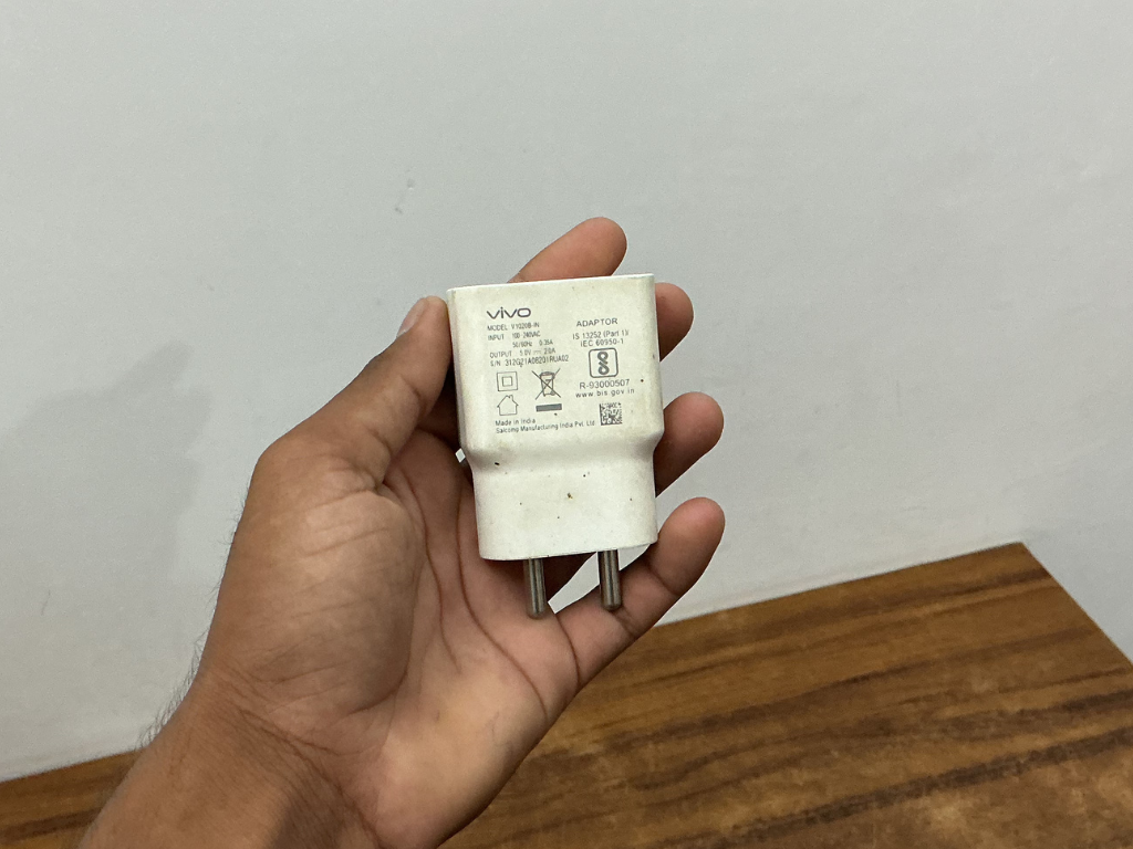
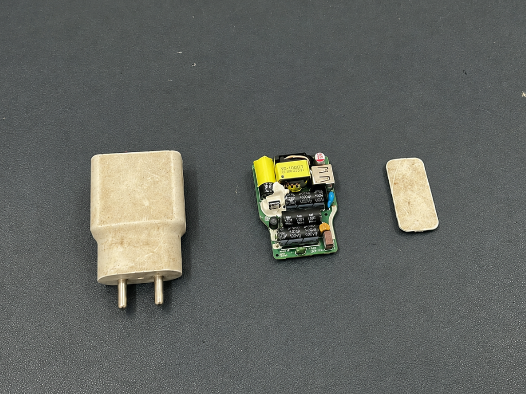
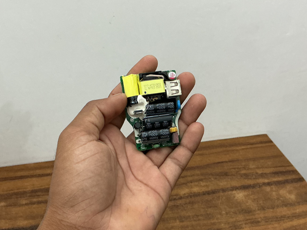
Since the ESP32-S3 cannot be powered directly from the AC mains, we need a power supply to convert the mains voltage into a safe 5V DC output.
You can use any suitable 5V SMPS module for this purpose. In my case, I repurposed an old smartphone charger that was no longer being used. These chargers already contain a compact and reliable SMPS circuit, making them perfect for DIY projects.
Start by carefully opening the charger enclosure and removing the internal power supply board. Be gentle during this process to avoid damaging any components or tracks on the PCB.
Once removed, inspect the board and identify the AC input and 5V output connections. This compact power supply will be used to power the Arduino and other low-voltage electronics inside AirSense.
⚠️ Warning: This section involves working with mains voltage. Always disconnect power before handling the circuit and take appropriate safety precautions.
Step 11: Create Things
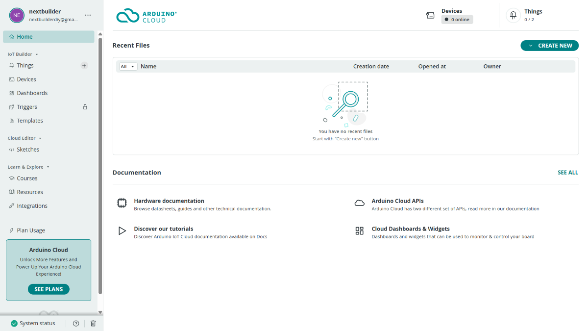
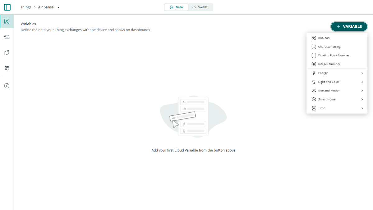
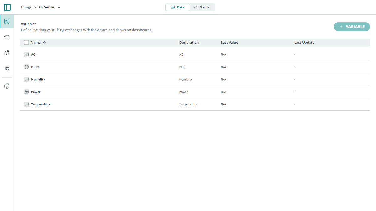
To enable remote monitoring and control, we need to create a new Thing in Arduino IoT Cloud and add the required cloud variables.
Sign In to Arduino IoT Cloud
Open Arduino IoT Cloud and sign in with your Arduino account.
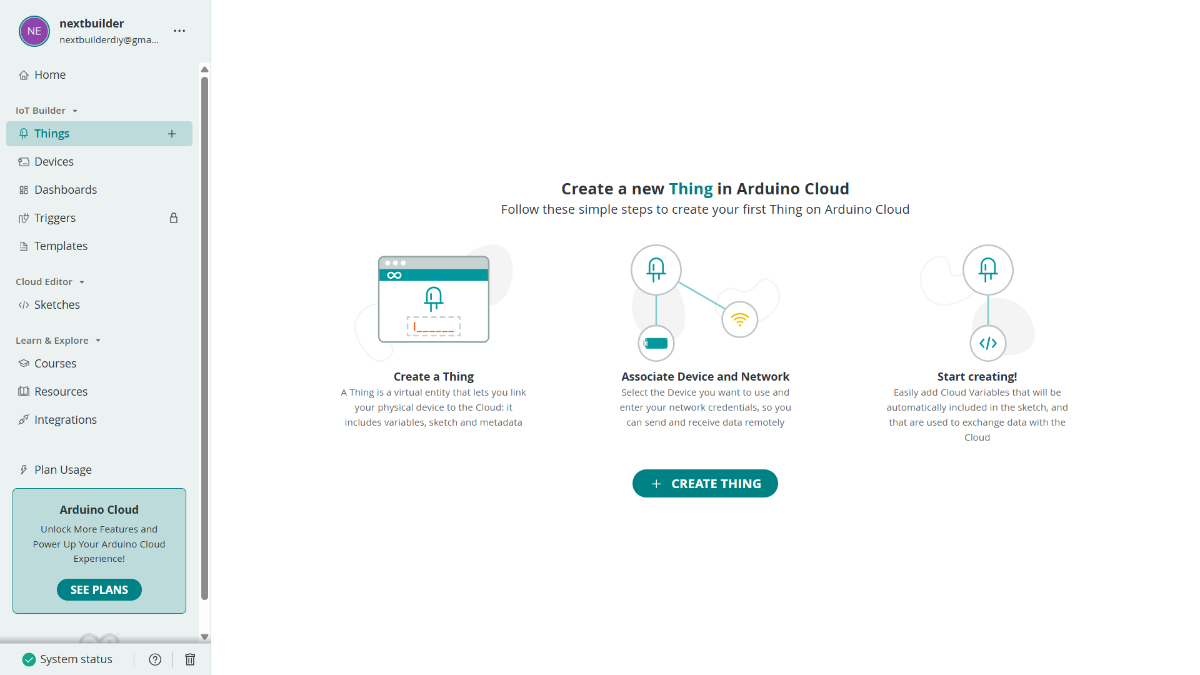
Create a New Thing
Home → Things → Create Thing (Enter a name for your project, such as: Air Sense)
Add Cloud Variables
Click + Variable and create the following variables:
- AQI (Integer Number) Read Only On Change
- DUST (Floating Point Number) Read Only On Change
- Temperature (Floating Point Number) Read Only On Change
- Humidity (Floating Point Number) Read Only On Change
- Power (Boolean) Read & Write On Change
💡 Note: The free Arduino IoT Cloud plan allows a maximum of 5 cloud variables, which is why only the essential variables are used in this project. Once created, Arduino IoT Cloud will automatically generate the required code definitions for your sketch.
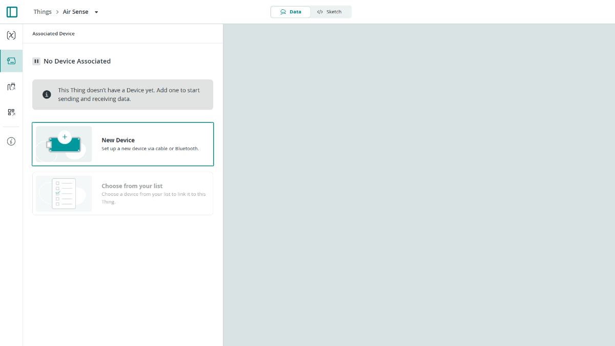
Step 12: Connect Board to Cloud
.png)
.png)
.png)
.png)
.png)
Open Associated Device → Add Device → Compatible Device.
Search for ESP32-S3 and select ESP32-S3 Dev Module from the list. Enter a name for your device, such as Air Sense, and continue with the setup.
Arduino IoT Cloud will generate a Device ID and Secret Key for your board. Download the provided PDF and save it safely, as these credentials will be required later in the firmware configuration.
After creating the device, open the Network Credentials page and enter your Wi-Fi SSID, Wi-Fi Password, and the Secret Key generated during device setup. Once all the details have been entered, click Save and Upload later.
💡 Note: The Device ID and Secret Key from the downloaded PDF will be used in the code setup step to securely connect Air Sense to Arduino IoT Cloud.
Step 13: Air Sense Dashboard
.png)
.png)
.png)
.png)
.png)
.png)
.png)
.png)
The Dashboard allows you to monitor sensor values and control devices in real-time from any browser or mobile device.
Arduino Cloud → Dashboards → Create Dashboard
→ Enter Air Sense Dashboard as the dashboard name.
Add the AQI Gauge
- ADD: Gauge
- Name: AQI
- Set Range: 0 to 400
- Link Variable: Air Sense → AQI
- Click Done
Add the PM2.5 Display
- ADD: Value
- Name: PM2.5
- Link Variable: Air Sense → DUST
- Select the Air/Wind icon
- Click Done
Add the Temperature Display
- ADD: Value
- Name: Temperature
- Link Variable: Air Sense → Temperature
- Select the Thermometer icon
- Click Done
Add the Humidity Display
- ADD: Value
- Name: Humidity
- Link Variable: Air Sense → Humidity
- Select the Water Drop icon
- Click Done
Add Fan Control
- ADD: Switch
- Name: Fan
- Link Variable: Air Sense → Power
- Click Done
Step 14: Sensors & Data
This is the brain of Air Sense. Three data sources feed the dashboard every 2 seconds.
BME680 Sensor
float gas = bme.gas_resistance / 1000.0f;
float iaqPercent = (gas - 10) * 100.0f / (200.0f - 10.0f);
g_data.iaq = constrain(iaqPercent, 0, 100);
Reads temperature, humidity, pressure, and gas resistance. The gas resistance is converted into an IAQ (Indoor Air Quality) percentage — higher gas resistance means cleaner air, mapped to 0–100%.
Dust Sensor
digitalWrite(DUST_ILED_PIN, HIGH);
delayMicroseconds(280);
int raw = analogRead(DUST_AOUT_PIN);
delayMicroseconds(40);
digitalWrite(DUST_ILED_PIN, LOW);
float voltage = raw * (3.3f / 4095.0f);
float dust_ug = voltage * 200.0f;
An optical dust sensor that pulses an IR LED for exactly 280µs, reads the analog voltage during the dust-scatter window, then converts it to µg/m³. The timing is critical — off by even 10µs and readings drift.
AQI Calculation
int calcAQI(float pm25, float iaq) {
// EPA PM2.5 breakpoints → score p
return (int)(p * 0.7f + (100.f - iaq) * 1.5f * 0.3f);
}
Both PM2.5 and IAQ feed a blended AQI formula using EPA breakpoints — PM2.5 contributes 70%, gas quality contributes 30%
Filter Life Tracker
float calculateFilterLife() {
return 100.0f - (fanRuntimeSeconds / 360000.0f);
}
Every second the fan is running, a counter increments. A full 100-hour HEPA lifespan = 360,000 seconds, so filter life drains linearly. It shows a warning label on screen at ≤20% and a "Replace Filter" alert at ≤10%.
Step 15: Display Layout
The screen is 320×240, driven by TFT_eSPI with LVGL running on a hardware timer interrupt for smooth 1ms ticks. Two frame buffers enable flicker-free partial rendering.
Layout grid: The screen is divided into a 3-column, 3-row grid:
- Left column (x=2): PM2.5, Temperature, Humidity cards
- Right column (x=222): Pressure, IAQ, Filter Life cards
- Center column (x=101, w=118): AQI circle + WiFi status card
AQI Circle: The centerpiece:
A layered arc widget with a glowing outer ring, a dark inner fill, and color that changes with EPA category (green → yellow → orange → red → purple → maroon). The status text wraps automatically for long labels like "Unhealthy for Sensitive Groups."
Animations: Run every 16ms in the loop():
- animateGlow() — smoothly pulses the AQI ring opacity using a cubic ease curve
- animateWiFi() — fast-pulses the WiFi dot (90-frame cycle) to show live status
The boot sequence plays a sweeping green arc before the dashboard appears, giving the device a polished power-on feel.
Step 16: WiFi & Cloud
Air Sense connects to Arduino IoT Cloud over WiFi, letting you monitor all readings and remotely control the fan from any browser or the Arduino app.
Connection setup
Uses WiFiConnectionHandler with your SSID and password. ArduinoCloud.begin() handles reconnection automatically if WiFi drops.
Cloud variables
These Values are declared globally and registered with initProperties():
ArduinoCloud.addProperty(DUST, READ, ON_CHANGE, NULL);
ArduinoCloud.addProperty(Humidity, READ, ON_CHANGE, NULL);
ArduinoCloud.addProperty(Temperature, READ, ON_CHANGE, NULL);
ArduinoCloud.addProperty(AQI, READ, ON_CHANGE, NULL);
ArduinoCloud.addProperty(Power, READWRITE, ON_CHANGE, onPowerChange);
DUST, Temperature, Humidity, and AQI are read-only — the device pushes them to the cloud every time they change. Power is read-write, so you can toggle it from the cloud dashboard and it instantly fires the callback:
void onPowerChange() {
digitalWrite(RELAY_PIN, Power ? HIGH : LOW);
fanIsOn = Power;
}
This also updates the fanIsOn flag so filter life tracking stays accurate even when the fan is controlled remotely.
The WiFi card on the display shows CONNECTED (white) or OFFLINE (red) with a pulsing dot — so you always know at a glance whether cloud sync is live.
Step 17: Installing the Required Libraries
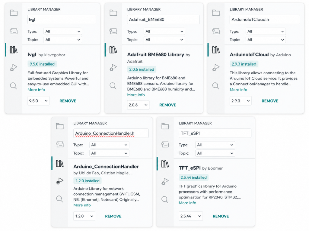
Before uploading the code, install all the required libraries through the Arduino IDE Library Manager. These libraries provide support for the TFT display, LVGL graphical interface, environmental sensing, Wi-Fi connectivity, and Arduino Cloud integration.
Open Arduino IDE → Library Manager and install the following libraries:
- TFT_eSPI
- LVGL
- Adafruit BME680
- ArduinoIoTCloud
- Arduino_ConnectionHandler
The remaining libraries such as Arduino.h, SPI, Wire, and WiFi are included with the board package and do not require separate installation.
After installing all the libraries, restart the Arduino IDE to ensure that every dependency is loaded correctly before compiling the project.
Step 18: Library Configuration
To ensure the display and graphical user interface work correctly, a few library files must be configured before compiling the firmware.
TFT_eSPI Configuration
Open the Arduino libraries directory on your computer and navigate to the TFT_eSPI folder. Replace the existing User_Setup.h file with the custom version provided in this project's GitHub repository. This file contains the display driver configuration, pin mappings, and other settings required for the Air Sense display.
LVGL Configuration
Next, open the LVGL library folder and copy the provided lv_conf.h file from the project GitHub repository into the library directory. Similar to the TFT_eSPI configuration, this is a custom file created specifically for this project. It contains the LVGL settings, memory configuration, and graphical parameters required for the Air Sense user interface.
Both User_Setup.h and lv_conf.h are included in the project's GitHub repository and must be installed before compiling the code.
Step 19: Code Configuration
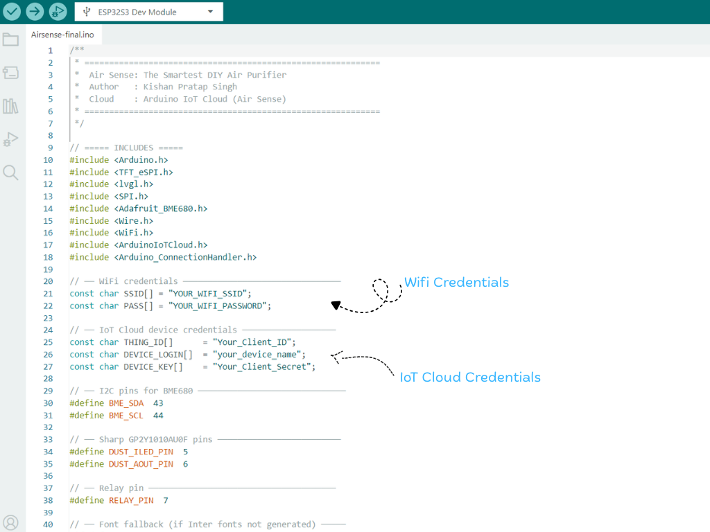
Before uploading the firmware, update the Wi-Fi and Arduino Cloud credentials with your own information.
Wi-Fi Configuration
Locate the following lines in the code:
const char SSID[] = "YOUR_WIFI_SSID";
const char PASS[] = "YOUR_WIFI_PASSWORD";
Replace YOUR_WIFI_SSID and YOUR_WIFI_PASSWORD with the name and password of your Wi-Fi network. These credentials allow the Air Sense system to connect to the internet and communicate with Arduino Cloud.
Arduino Cloud Configuration
Next, update the Arduino Cloud device credentials:
const char THING_ID[] = "Your_Thing_ID";
const char DEVICE_LOGIN[] = "Your_Device_Login";
const char DEVICE_KEY[] = "Your_Client_Secret";- THING_ID -> Arduino Cloud > Things > (Your Thing) > ⓘ Info > Thing ID
- DEVICE_LOGIN -> Downloaded Arduino IoT Cloud PDF > Client ID
- DEVICE_KEY -> Downloaded Arduino IoT Cloud PDF > Client Secret (Secret Key)
Replace these values with the credentials generated during the Arduino Cloud setup process. You can find them in the device configuration PDF that was downloaded earlier when the board was connected to Arduino Cloud. These credentials uniquely identify your device and enable secure communication with your cloud dashboard.
Step 20: Uploading Code
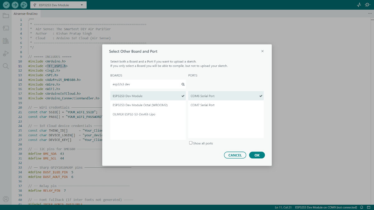
After updating all Wi-Fi and Arduino IoT Cloud credentials and installing the required libraries, Connect the ESP32-S3 board to your computer using a USB Type-C cable and open the project in the Arduino IDE. From the Tools menu, configure the following recommended board settings:
- Board: ESP32S3 Dev Module
- USB CDC On Boot: Enabled
- Flash Mode: QIO 80MHz
- Flash Size: 4MB (32Mb)
- Partition Scheme: Huge APP (3MB No OTA / 1MB SPIFFS)
- PSRAM: Disabled
- Upload Speed: 921600
Next, select the correct COM Port corresponding to your ESP32-S3 board. Once everything is configured, click the Upload button and wait for the compilation and upload process to complete.
After a successful upload, the Air Sense device will automatically connect to your Wi-Fi network, synchronize with Arduino IoT Cloud, initialize all connected sensors, and begin monitoring air quality data in real time. The live sensor readings will also be available through your Arduino IoT Cloud dashboard, allowing you to monitor your indoor environment remotely from anywhere.
Step 21: Microcontroller Assembly
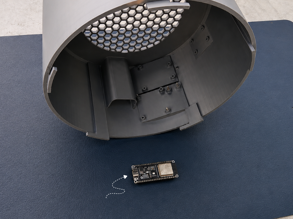
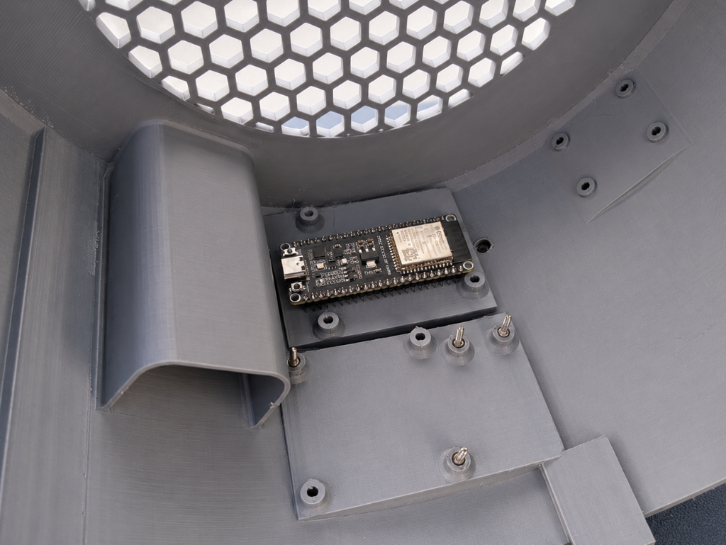
Place the ESP32 S3 onto the dedicated mounting platform inside the enclosure. Align the mounting holes of the board with the printed standoffs.
Once aligned, secure the board using M3 screws. Tighten the screws carefully until the board is firmly held in place. Avoid over-tightening, as this may damage the PCB or the mounting posts.
Step 22: Dust Sensor Assembly
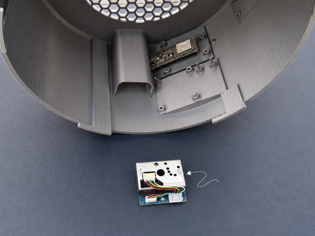
The dust sensor is responsible for measuring the concentration of fine particulate matter in the air, helping the system monitor air quality and calculate the Air Quality Index (AQI) in real time.
Place the dust sensor module onto its dedicated mounting platform inside the enclosure, directly beneath the air intake channel. This position ensures that airflow passes smoothly through the sensor, allowing accurate particle detection.
Align the mounting holes with the printed standoffs and secure the module using M3 screws. Make sure the sensor is firmly mounted and that the connector remains accessible for wiring.
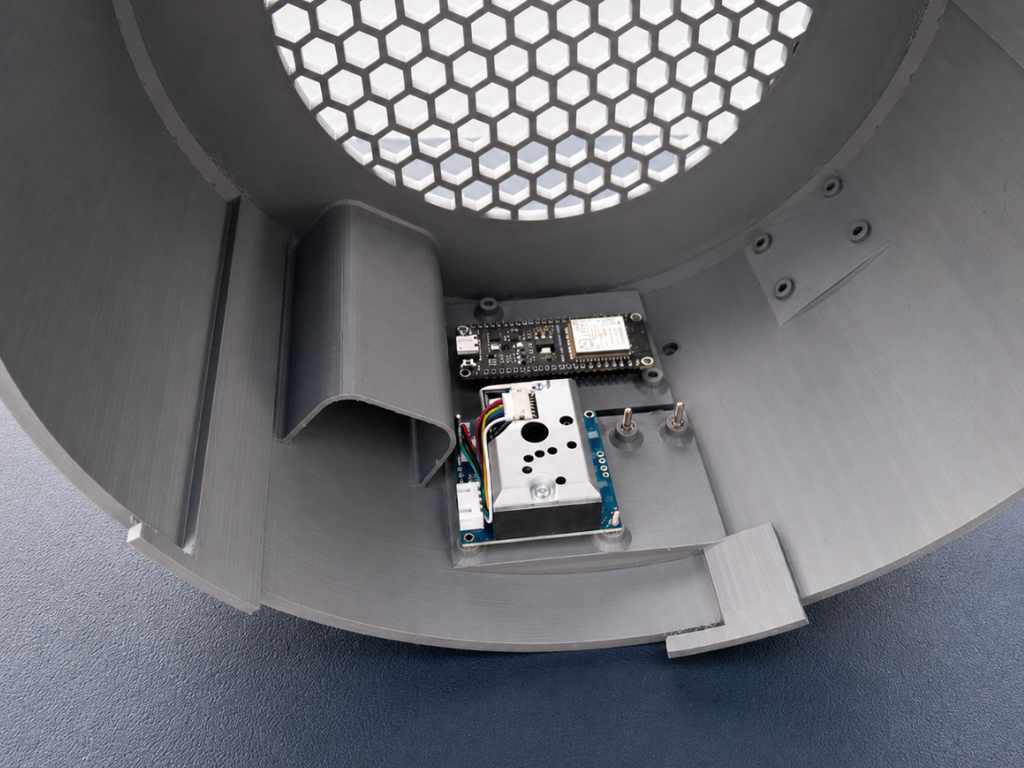
Step 23: BME680 Sensor Assembly
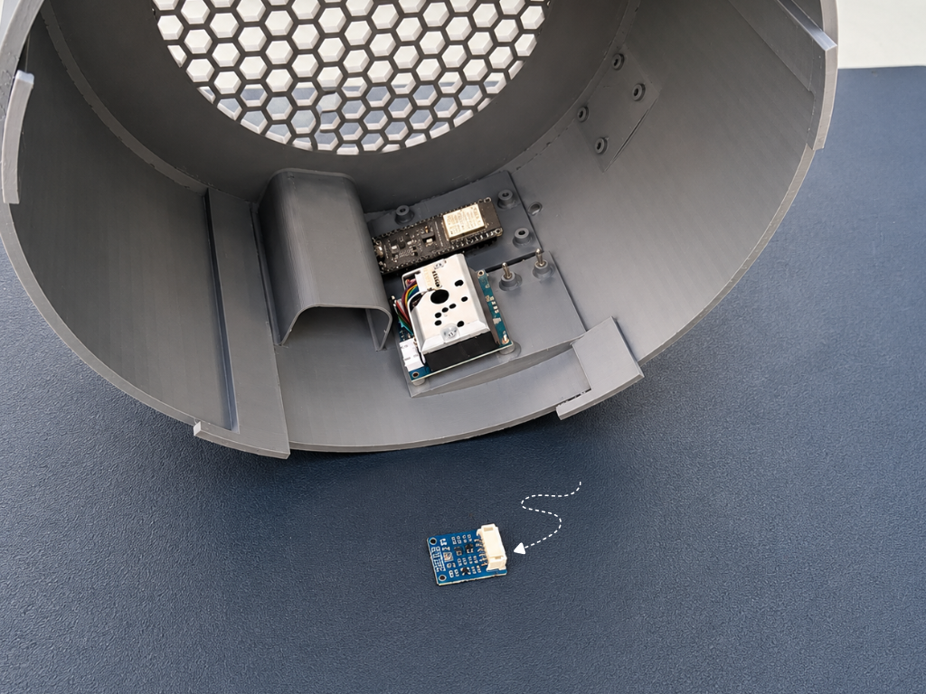
The BME680 is a compact environmental sensor that measures temperature, humidity, air pressure, and gas resistance. These readings help monitor indoor environmental conditions and improve overall air quality analysis.
Place the BME680 sensor module onto its designated mounting location beside the dust sensor assembly. This position keeps the sensor exposed to the airflow inside the enclosure, ensuring accurate environmental measurements.
Align the sensor board with the mounting area and secure it in place. Ensure the connector faces outward for easy cable routing and future maintenance.
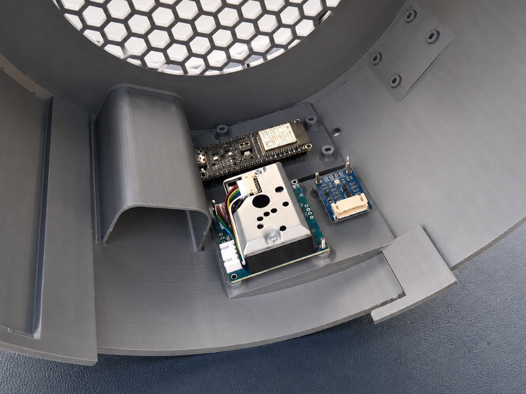
Step 24: Relay Module Assembly
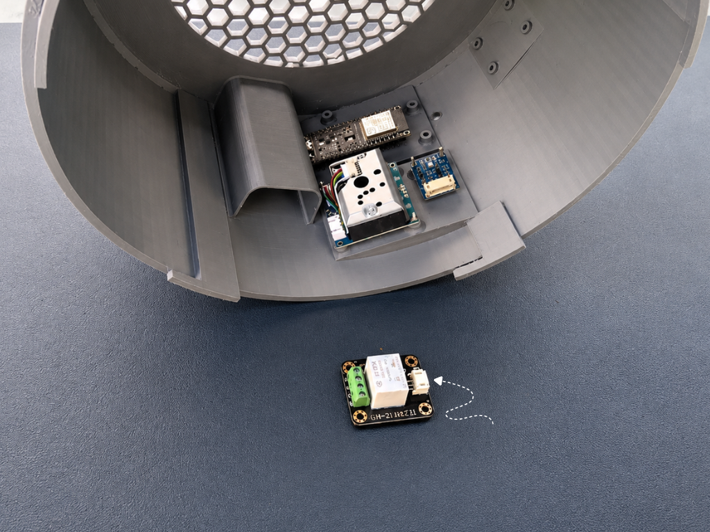
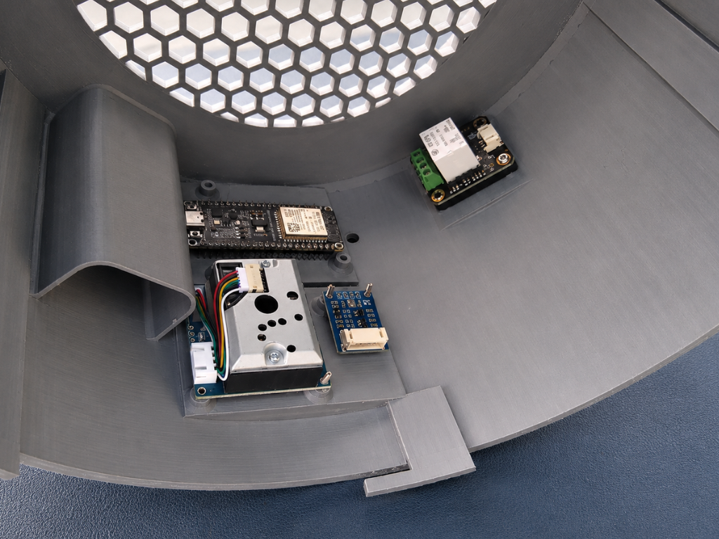
The relay module acts as the switching interface between the Air Sense system. It allows the microcontroller to safely control high-voltage equipment such as exhaust fan.
Position the relay module on its dedicated mounting platform inside the enclosure, ensuring the terminal block faces outward for convenient wiring access. This placement keeps the control and power connections organized while maintaining a compact internal layout.
Secure the relay module using M3 screws and verify that it is firmly mounted. Ensure adequate clearance around the terminal block so external wires can be connected easily during final assembly.
Step 25: 5V Adapter Assembly
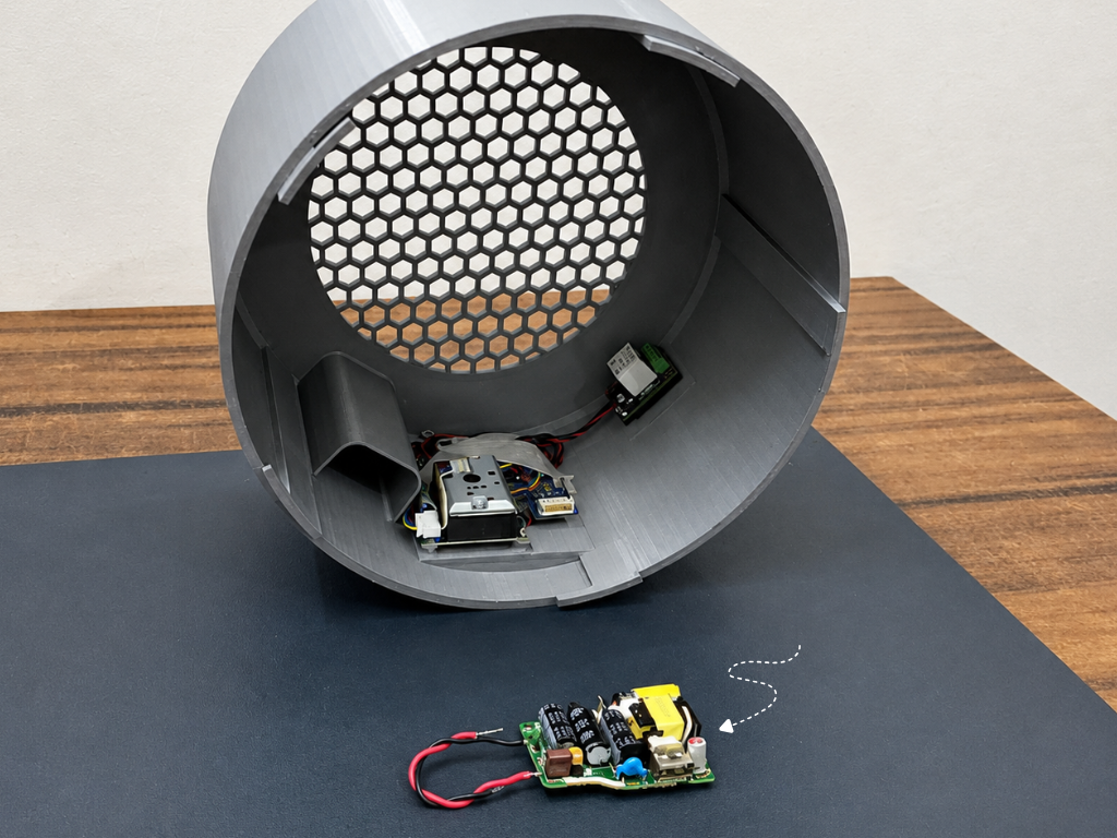
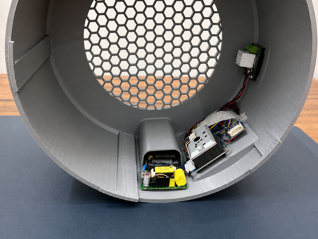
To power the electronics safely, install the 5V AC-to-DC power supply module inside the dedicated compartment of the enclosure. Position the module below the cable channel and secure it firmly in place.
The adapter converts the mains AC voltage into a stable 5V DC output, which powers the ESP32-S3, sensors, display, and relay module. This eliminates the need for external power supplies and keeps all electronics neatly integrated inside the enclosure.
Step 26: Display Assembly
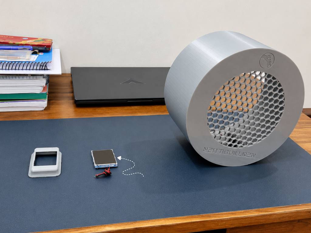
The TFT display serves as the primary user interface of the Air Sense system, providing real-time information such as AQI, PM2.5 concentration, temperature, humidity, device status, and system alerts.
Begin by placing the display module into the dedicated display Cover. Ensure the screen sits flush within the frame and that the display area is properly aligned with the viewing window.
Once the display is secured in the 3d printed cover, carefully insert the assembled display unit into the display opening located on the top side of the enclosure. Press it gently into position until it fits securely and aligns with the enclosure surface.
Step 27: AC Power Cord Installation
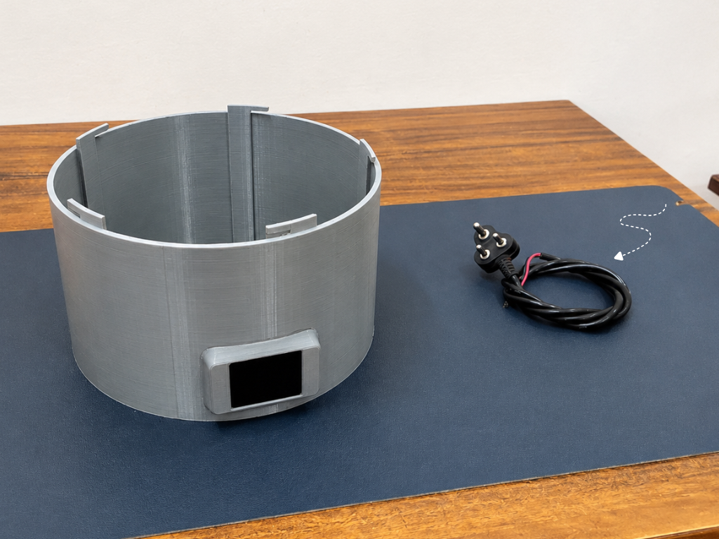
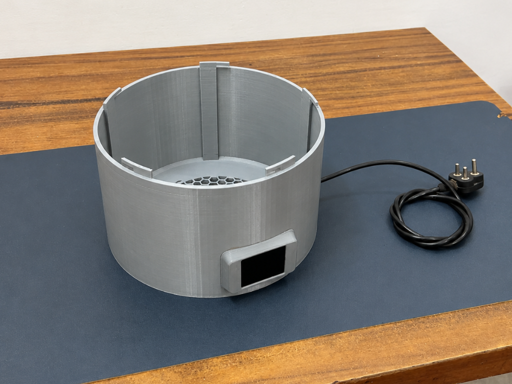
To provide mains power to the system, install the AC power cord through the dedicated cable entry slot in the enclosure. Route the cable neatly inside the housing.
The power cord serves as the main power source for the Air Sense purifier, delivering AC power from the wall outlet to the internal power supply & Exaust Fan.
Step 28: Wiring Connections
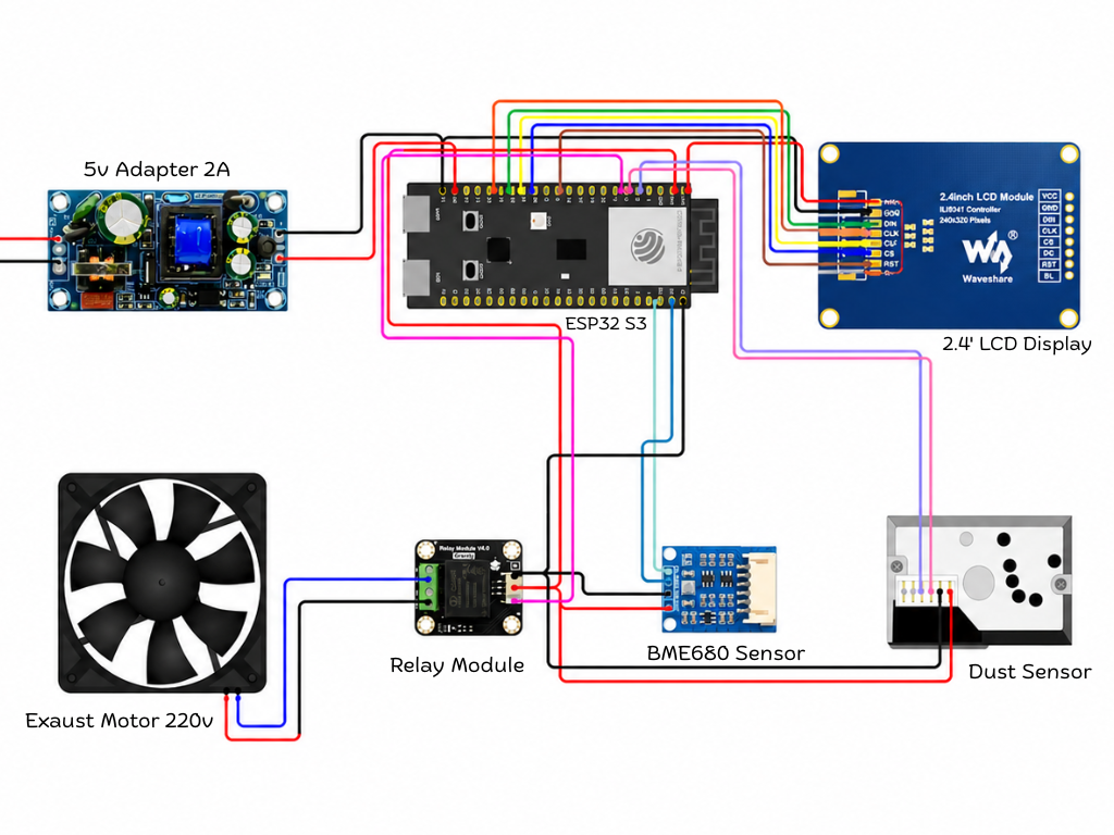
Now it's time to connect all the modules to the ESP32-S3-Zero. Follow the wiring carefully and double-check every connection before powering the system.
Display Connections
Connect the display module to the ESP32-S3 as follows:
- VCC → 3.3V
- GND → GND
- DIN → GPIO11
- CLK → GPIO12
- CS → GPIO10
- DC → GPIO9
- RST → GPIO8
- BL → 3.3V
BME680 Air Quality Sensor
The BME680 communicates using the I²C interface.
- VCC → 3.3V
- GND → GND
- SDA → GPIO43
- SCL → GPIO44
Dust Sensor
Connect the dust sensor according to the following wiring:
- VCC → 3.3V
- GND → GND
- ILED → GPIO5
- AOUT → GPIO6
Relay Module
The relay is used to automatically control the fan based on the measured air quality.
- VCC → 3.3V
- GND → GND
- Signal → GPIO7
Fan AC Wiring
⚠️ Warning: This section uses mains AC voltage. Proceed only if you are experienced with high-voltage wiring and ensure power is disconnected before making any connections.
Connect the relay and fan as follows:
- Wall Outlet Phase (Live) → Relay COM
- Relay NO → Fan Phase (Live)
- Wall Outlet Neutral → Fan Neutral
When the relay turns ON, the Phase line is connected through the relay, allowing power to reach the fan and start it automatically.
Step 29: Close the Housing
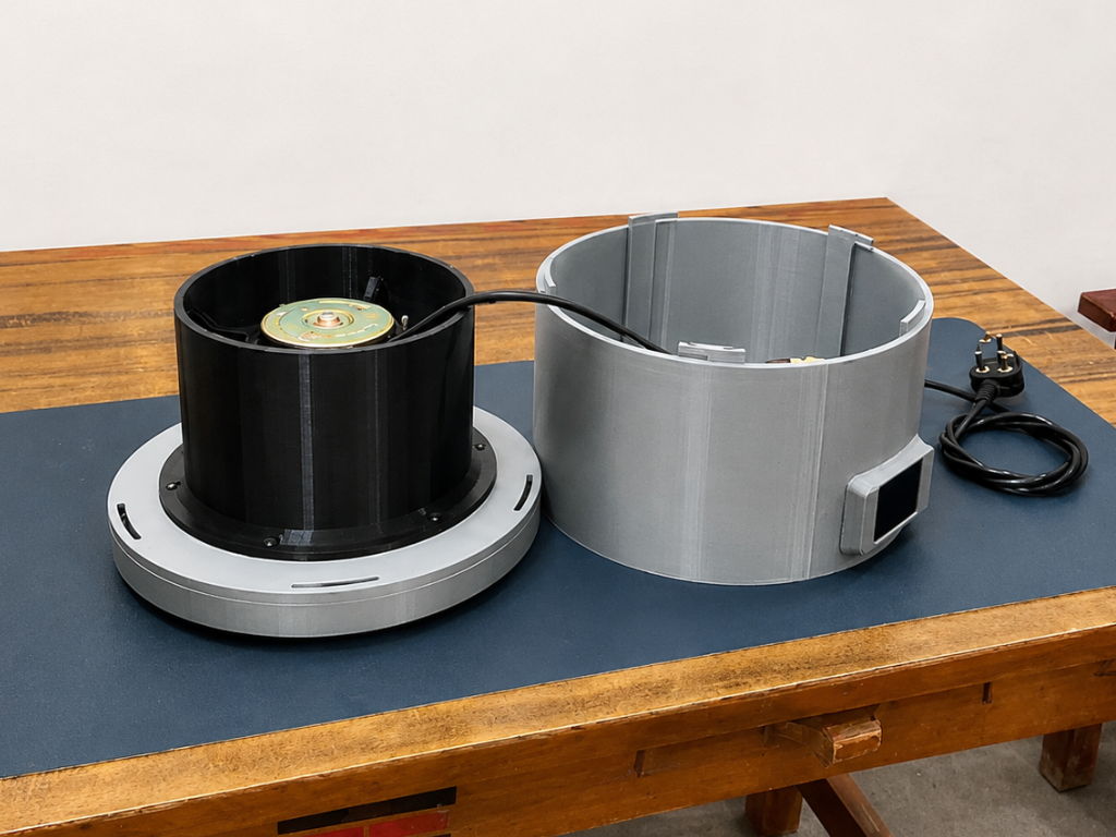
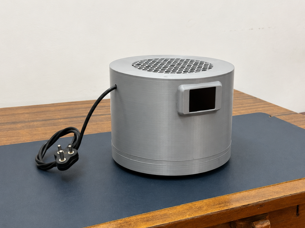
With all electronics, wiring, and internal components installed, the final step is to close the enclosure. Carefully align the upper housing with the motor assembly section, making sure the power cord and internal wires are routed properly and do not get pinched during assembly.
Once aligned, match the locking tabs of the housing with the corresponding slots on the base. Gently press the two sections together and rotate until they lock securely into place. The enclosure uses a twist-lock mechanism, so no screws are required.
Step 30: Final Assembly
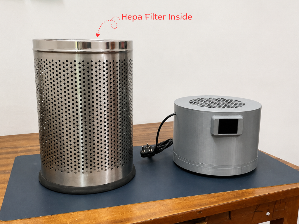
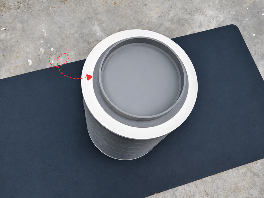
For the final assembly, place the completed Air Sense housing onto the HEPA filter unit. Carefully align the housing with the top rim of the filter assembly, ensuring it sits evenly and securely in position.
Once aligned, gently lower the housing onto the filter and rotate it until the locking tabs engage with the corresponding slots. The twist-lock mechanism securely joins both sections together, eliminating the need for screws while maintaining a clean, product-like appearance.
Before use, verify that the assembly is stable and that the HEPA filter is properly seated inside the purifier. The fan assembly will now draw contaminated air through the filter and exhaust clean air from the top of the unit. Whenever maintenance or filter replacement is required, simply rotate the housing in the opposite direction and lift it off for quick access to the internal components.
Step 31: Arduino Remote App
.png)
.png)
To monitor and control Air Sense directly from your smartphone, install the Arduino Remote app from the Google Play Store or Apple App Store and sign in using the same Arduino account connected to your Arduino IoT Cloud project.
After signing in, the app will automatically detect your Air Sense Thing and display all the cloud variables configured earlier. You can view real-time AQI, dust concentration, temperature, and humidity data, as well as remotely control the purifier's power state from anywhere with an internet connection.
Step 32: Testing
Now it's time to test the completed Air Sense Smart Air Purifier. Connect the AC power cord to a mains power outlet and switch it on. As soon as power is applied, the ESP32-S3, sensors, display, and fan will start automatically.
Within a few seconds, the front display will come to life and begin showing real-time air quality information, including AQI, PM2.5 concentration, temperature, humidity, pressure, IAQ level, Wi-Fi status, and filter life. The device will also connect to Arduino IoT Cloud and start updating data remotely.
At the same time, the fan will begin drawing in surrounding air through the filter system. Dust particles and other airborne pollutants are captured by the filter, while the cleaned and safer air is pushed back into the room.
You can also verify the live readings and control the purifier remotely using the Arduino Remote app or the Arduino IoT Cloud dashboard.
Conclusion
Air Sense is more than just a DIY air purifier—it's my attempt to use technology to create a healthier and smarter environment for everyone. Clean air is something we all deserve, and this project helps monitor air quality while automatically improving it in real time.
Throughout this project, I focused on making every step as clear and beginner-friendly as possible. My goal was to ensure that anyone, even with limited electronics experience, could successfully build and understand this project. I put a lot of effort into documenting each stage so that learning and building become equally enjoyable.
From the custom 3D-printed design created in Autodesk Fusion to the cloud-connected monitoring system, Air Sense combines practical functionality with a product-like appearance and user experience. It is not just a prototype—it is a real-world solution that can be used every day.
For me, dreaming of a better world means creating technology that improves people's lives in a meaningful way. By helping people monitor and improve the air they breathe, Air Sense contributes to a cleaner, healthier, and more informed future. I hope this project inspires others to learn, innovate, and build solutions that make a positive difference in the world.