Building AIRiSense Cloud: A Step-by-Step Guide
This list contains all the components I used:
https://www.digikey.in/en/mylists/list/WIWZJDLI2L
The Problem: Why Build This?
Indoor air pollution is often 2-5 times higher than outdoor levels. While developing this project, I analyzed existing market solutions and found a significant gap. Most affordable DIY monitors simply read the raw voltage from a sensor (0-3.3V) and display it as a number like "450." This is scientifically meaningless. Is 450 good? Is it bad? Without calibration against a baseline, it's just a number.
AIRiSense Cloud was engineered to solve this. It doesn't just read sensors; it interprets them. It uses a mathematical model to convert electrical resistance into Parts Per Million (PPM) and uses Artificial Intelligence to classify safety levels.
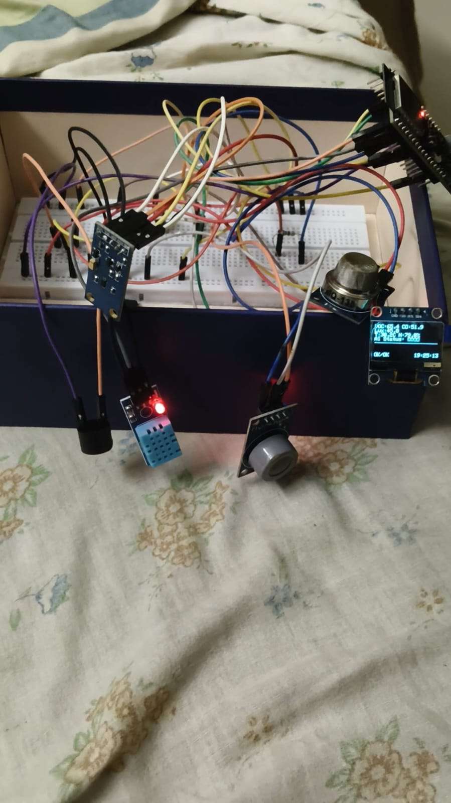
The complete AIRiSense Cloud system monitoring indoor air quality.
Hardware Architecture & Circuit Design
The system is built around the ESP32-C6-DevKitC-1. I chose this specific microcontroller for two reasons:
- RISC-V Architecture: It represents the future of open-source silicon.
- Wi-Fi 6 (802.11ax): It offers better power efficiency and reliable connectivity for IoT data streaming.
The Sensor Array
I designed a multi-sensor interface on a breadboard:
- MQ-135: Connected to GPIO 0. This detects a broad range of harmful gases like Ammonia, Benzene, and Smoke.
- MQ-7: Connected to GPIO 1. This is highly sensitive to Carbon Monoxide (CO), a silent killer in homes.
- DHT11: Connected to GPIO 4. Since gas sensors are affected by heat and moisture, monitoring temperature/humidity provides context for the data.
- BH1750: Connected via I2C (GPIO 21/22). This high-precision light sensor helps correlate air quality dips with human activity (e.g., lights on = cooking/working).
The Alert System (Driver Circuit)
A standard GPIO pin can only supply about 20mA of current. An active buzzer often draws more, which can damage the chip or result in a weak sound. To fix this, I built a low-side switch driver:
- I used a BC547 NPN Transistor.
- The Base is connected to GPIO 5 via a 10kΩ resistor (to limit current).
- The Collector connects to the buzzer's negative leg.
The Emitter connects to Ground.
This setup allows the ESP32 to safely trigger a loud, 5V-powered alarm with a tiny logic signal.
.png)
The circuit schematic showing the sensor array and the transistor driver for the buzzer.
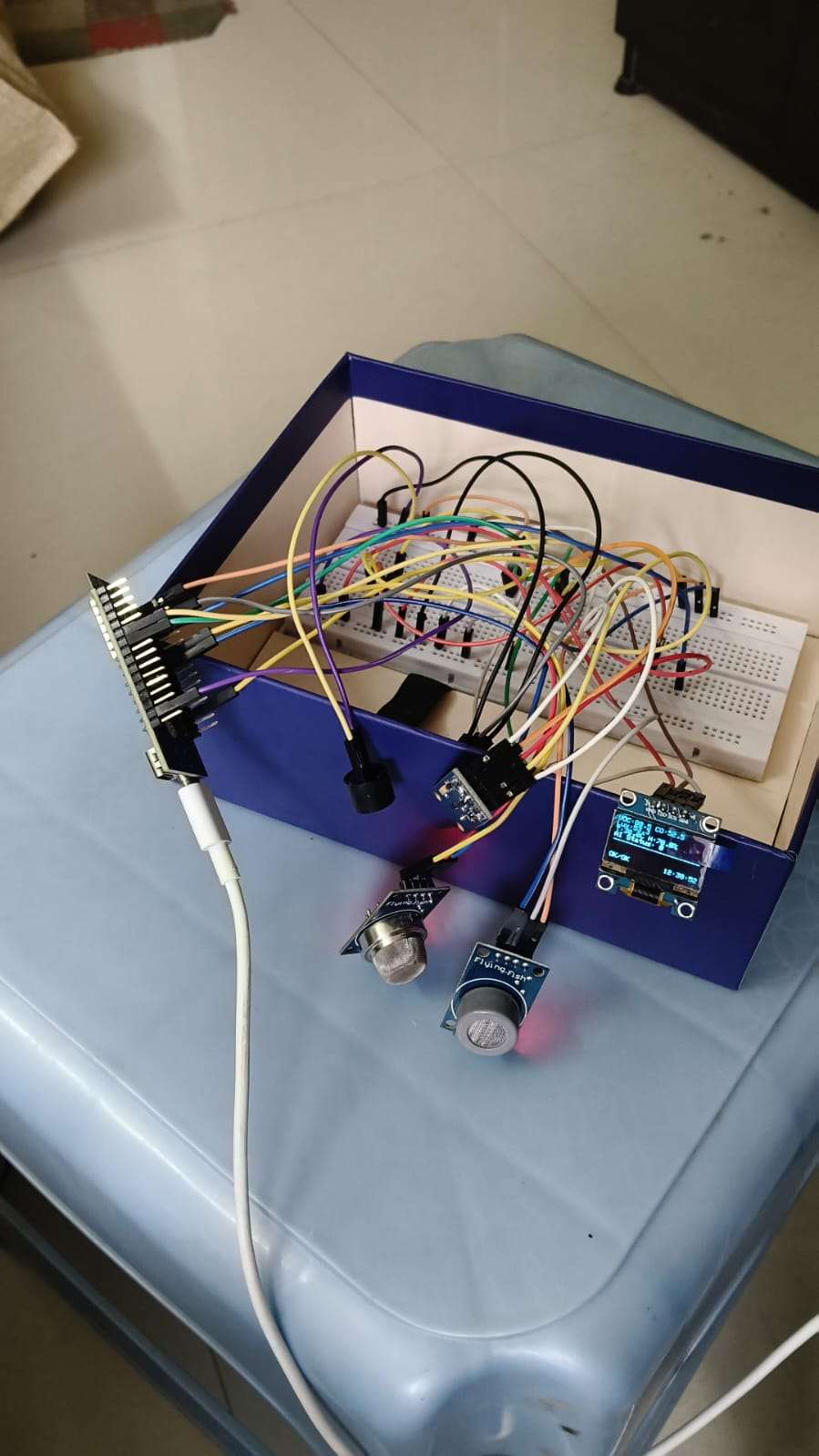
Physical implementation on a breadboard.
The Firmware Logic: Science meets Code
Phase 1: Calibration (The R0 Calculation)
Before the device can be used, it must know what "Clean Air" looks like. I wrote a specific calibration algorithm (calibration.ino) that runs the sensors for 30 minutes in an outdoor environment. It measures the resistance of the sensor's internal chemical layer to establish a baseline, known as R0.
C++
// Calibration Logic Snippet
float calculateResistance(int adc_value) {
  // Convert analog value (0-4095) into physical resistance
  return ((4095.0 * RL_VALUE) / adc_value) - RL_VALUE;
}
I recorded the unique R0 values for my specific sensors (MQ135: 15.29 kΩ, MQ7: 11.39 kΩ) and hard-coded them into the final firmware.
Phase 2: Real-Time PPM Conversion
In the main firmware, the device uses the logarithmic relationship derived from the sensor's datasheet to convert the current resistance ($R_S$) into concentration.
PPM = a * (Rs / R0)^b
Where a and b are constants specific to the target gas curve. This math ensures the numbers displayed on the screen are scientifically valid.
Edge AI Implementation (TinyML)
Instead of writing hundreds of if/then statements (e.g., "If humidity is high and CO is medium, then..."), I used Machine Learning.
- Data Forwarding: I wrote a sketch that streamed 5 data points (VOC, CO, Light, Temp, Humidity) to the serial port.
- Training in Edge Impulse: I collected three datasets: "Good Air," "Moderate" (stale air), and "Poor" (exposed to pollutants). I trained a Neural Network Classifier on this data.
- On-Device Inference: I exported the model as an Arduino C++ library. The ESP32-C6 runs this model locally. Every 5 seconds, it feeds the current sensor readings into the neural network, and the AI returns a probability score (e.g., "98% likely to be POOR").
This allows the device to detect complex pollution patterns that simple thresholds might miss.
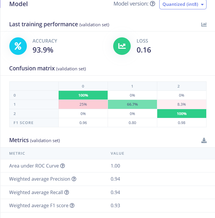
Training performance of the Neural Network showing high accuracy in classifying air quality states.
Cloud Integration & Bidirectional Control
The final piece of the puzzle is the Blynk IoT integration.
- Upstream Data: The ESP32 pushes the calculated PPM values and the AI status string to the cloud.
- Visual Dashboard: I built a web dashboard with Gauges for the analog data and a Label for the status.
Downstream Control (Remote Silence): I implemented a "Silence Alarm" feature using Virtual Pin V4.
- When the user flips the switch on the web dashboard, Blynk sends a
1to the device. - The
BLYNK_WRITE(V4)function triggers an interrupt on the ESP32. - The device immediately cuts power to the buzzer transistor and starts a non-blocking 5-minute timer, allowing the user to mute false alarms or deal with the situation without the noise.
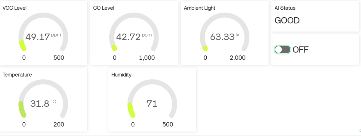
The AIRiSense Cloud dashboard interface.
I would like to show a real-time demo of my project. Here's the link to the youtube video: https://youtube.com/shorts/bD4XI3fXr38?feature=share
- When the user flips the switch on the web dashboard, Blynk sends a
AIRiSense Cloud is more than just a sensor reading tool; it is a complete, end-to-end IoT product prototype. By combining rigorous physics (calibration), advanced logic (Edge AI), and modern connectivity (Cloud), it demonstrates how accessible hardware can be used to build professional-grade safety equipment.
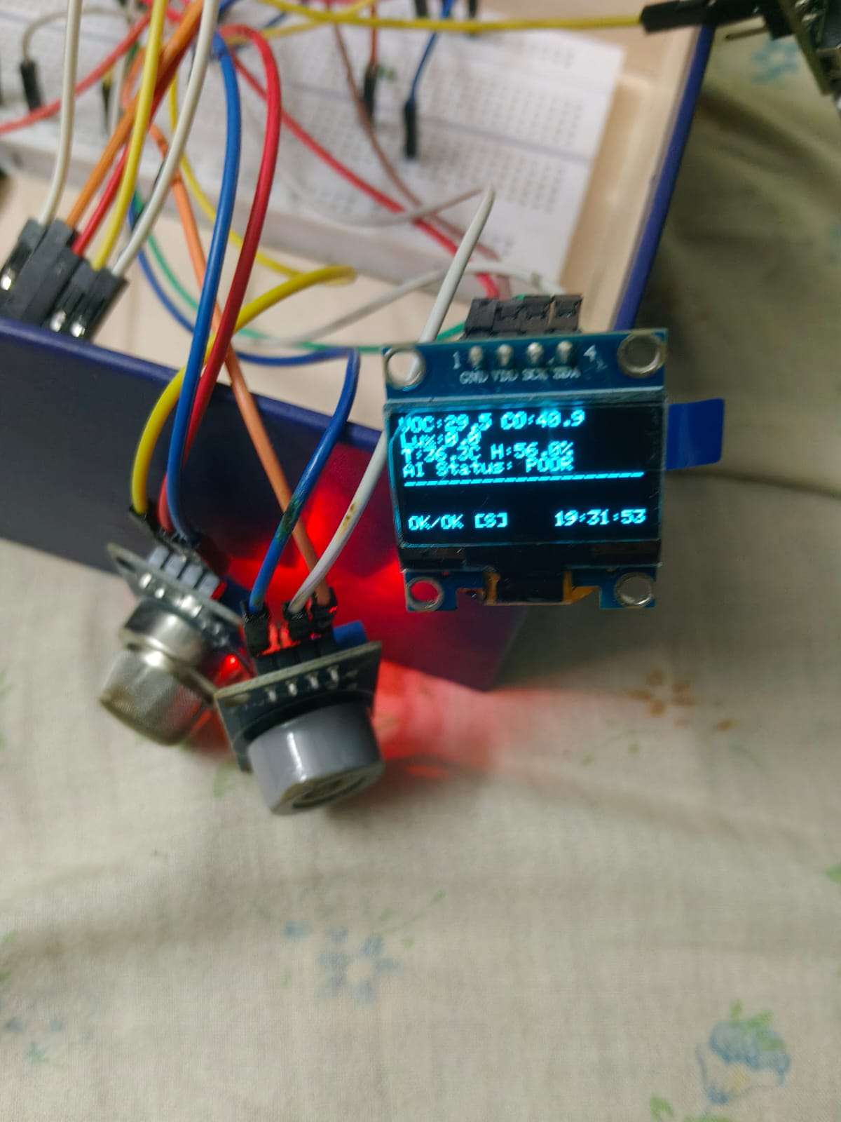
The device detecting a pollution event in real-time.