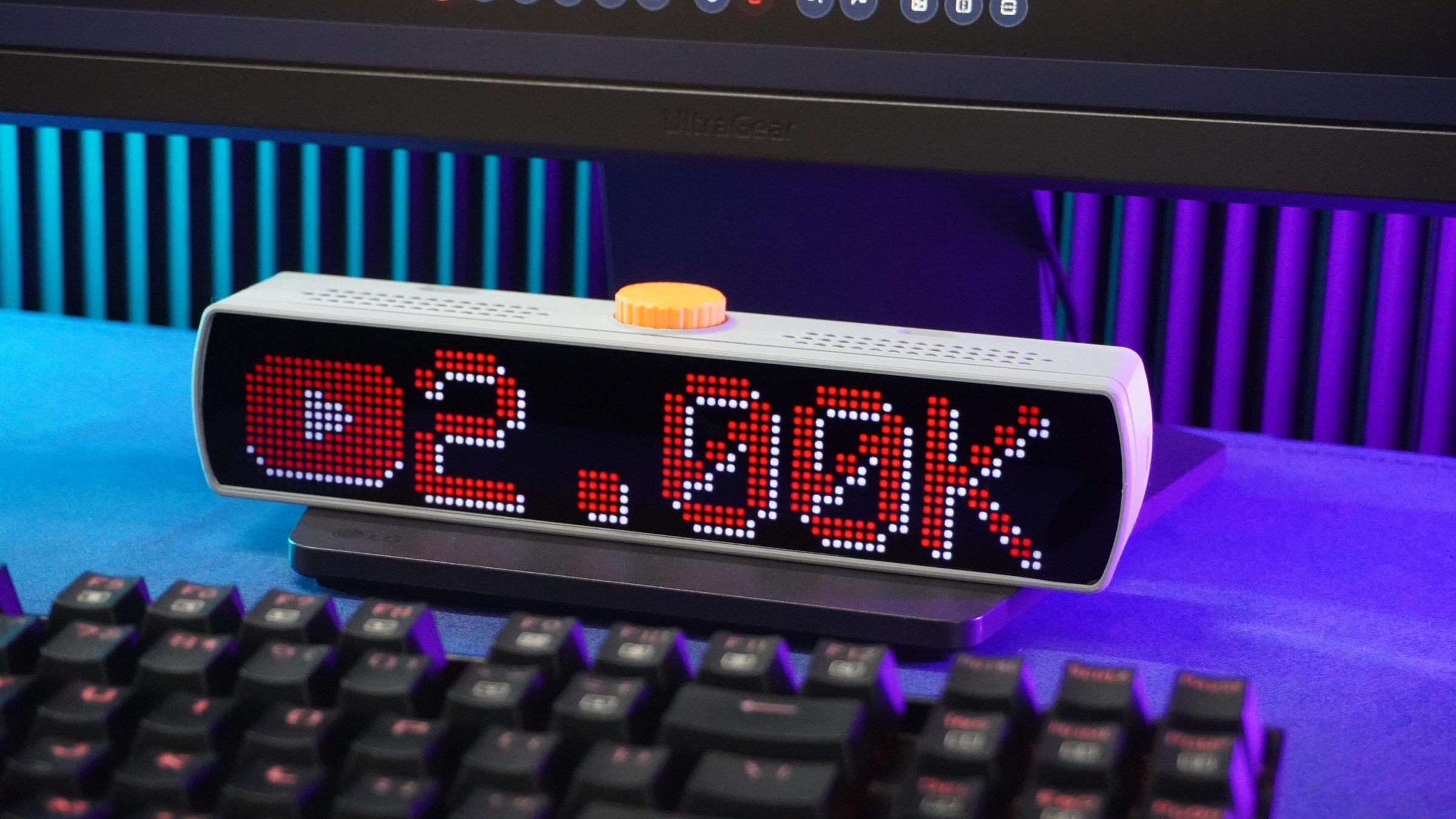
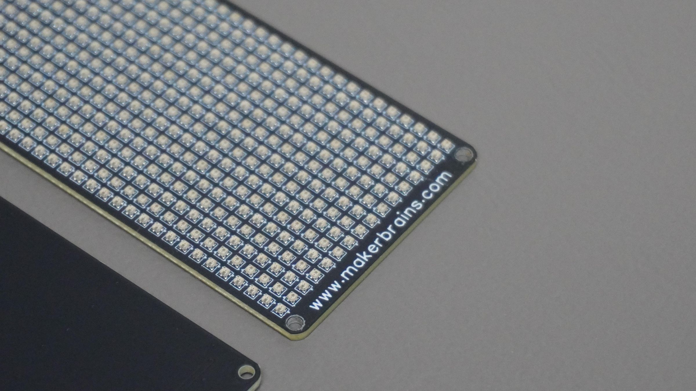
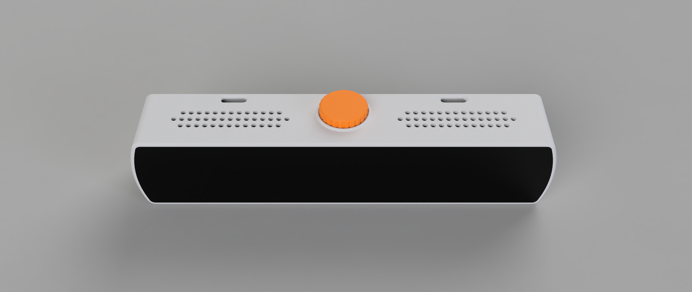
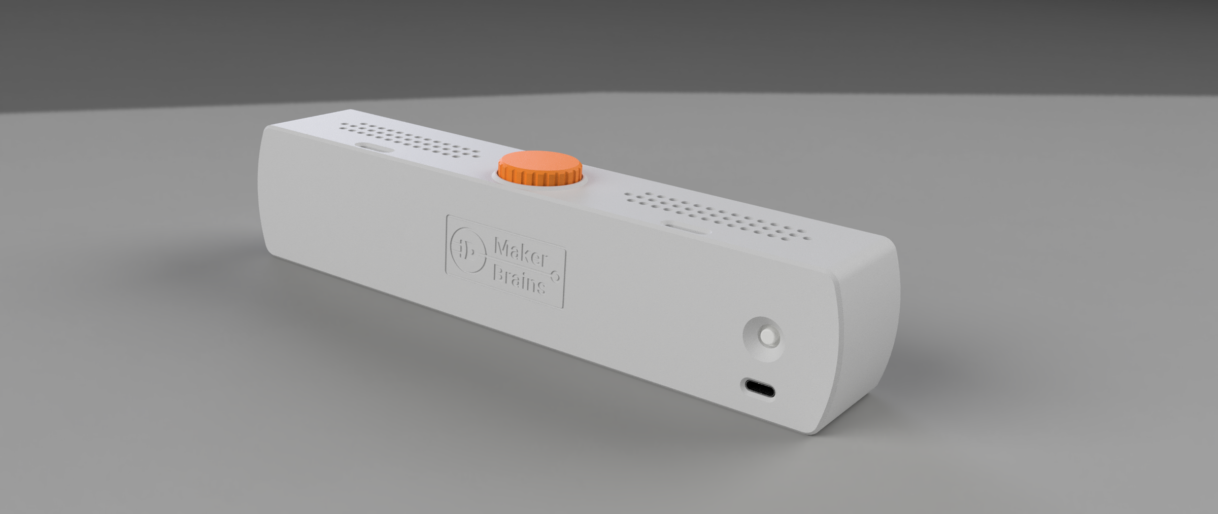
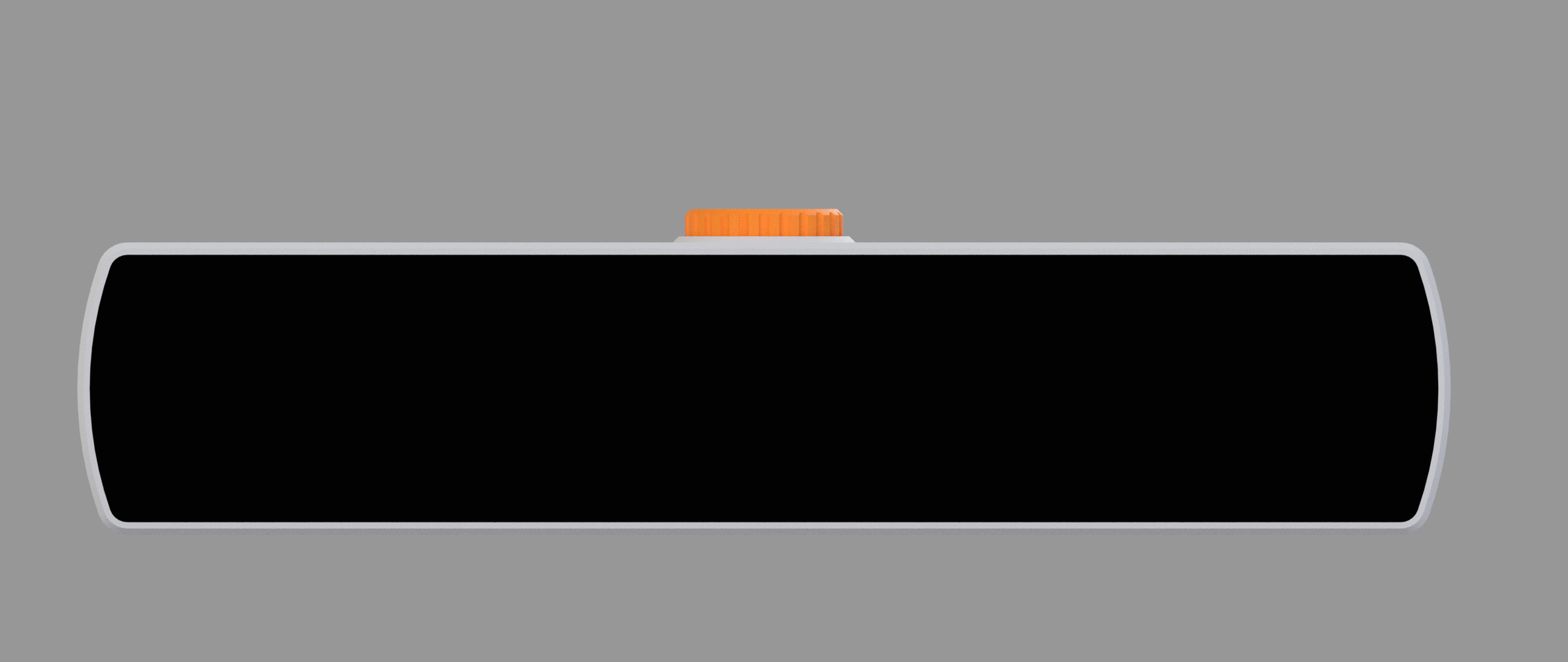
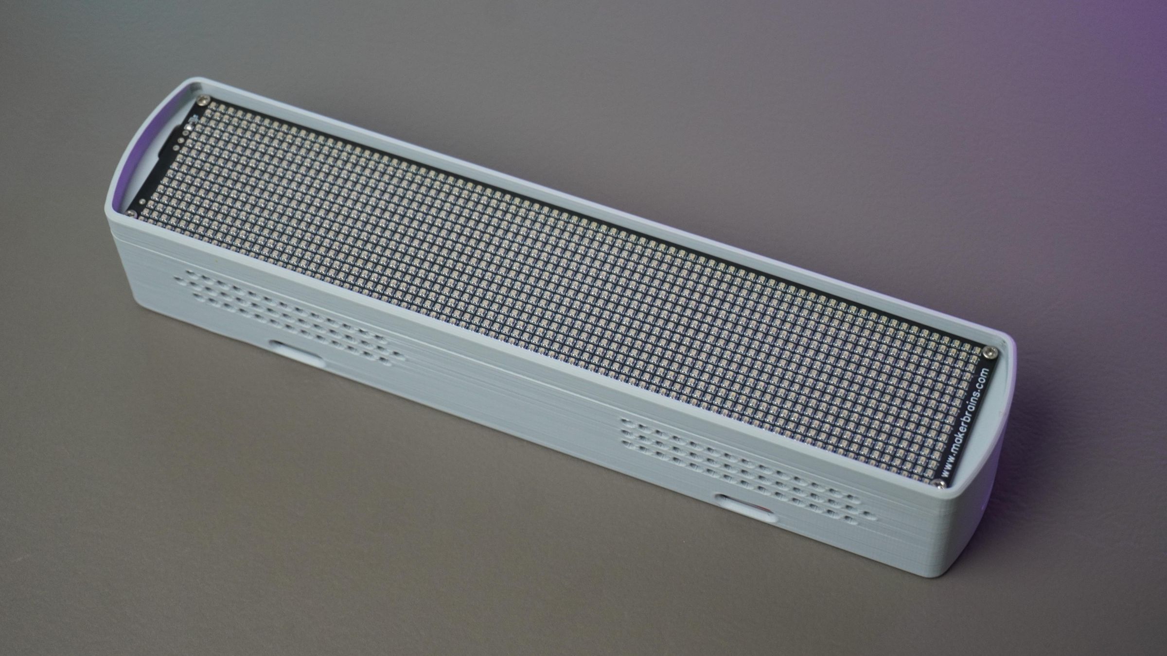
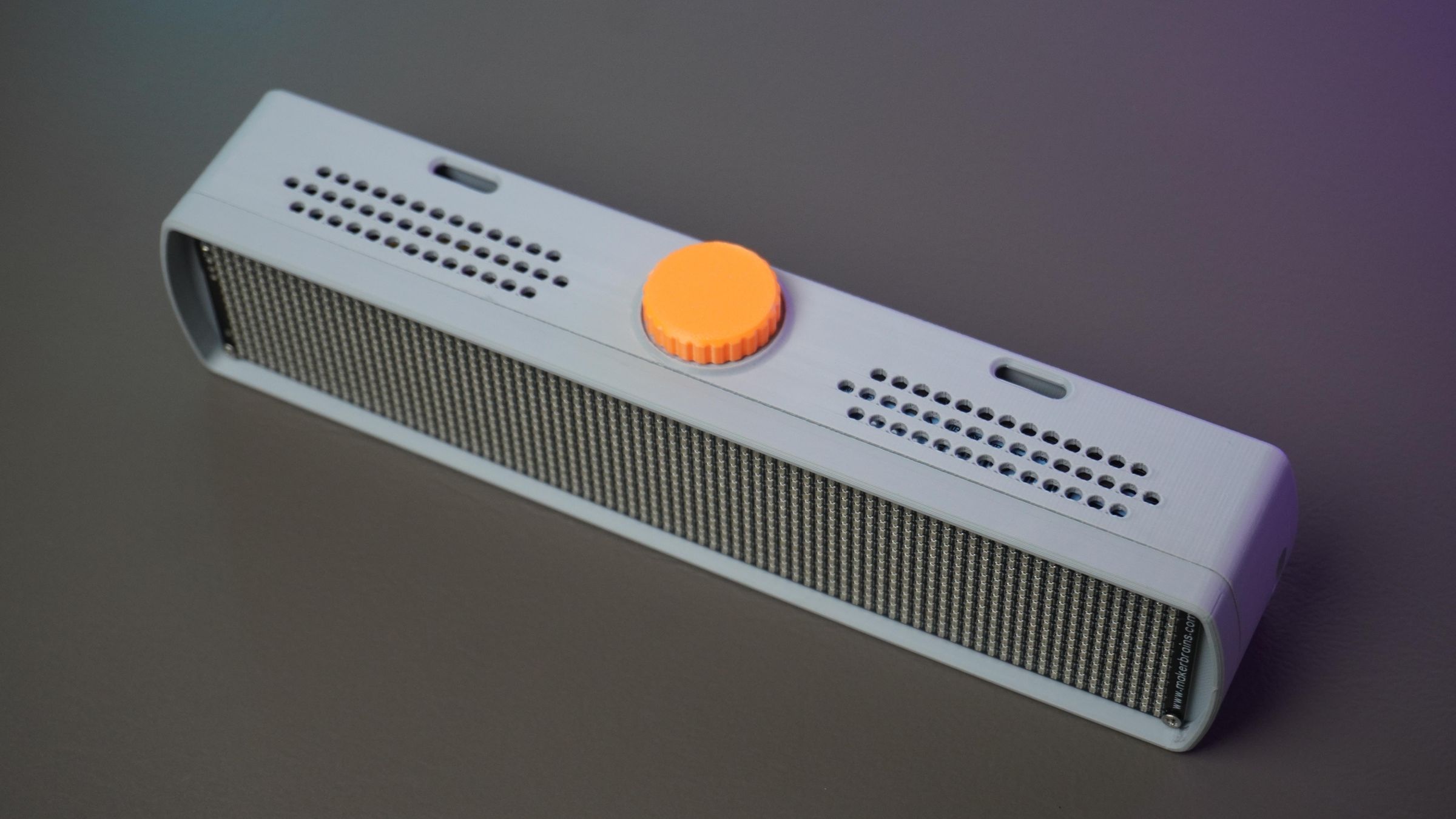
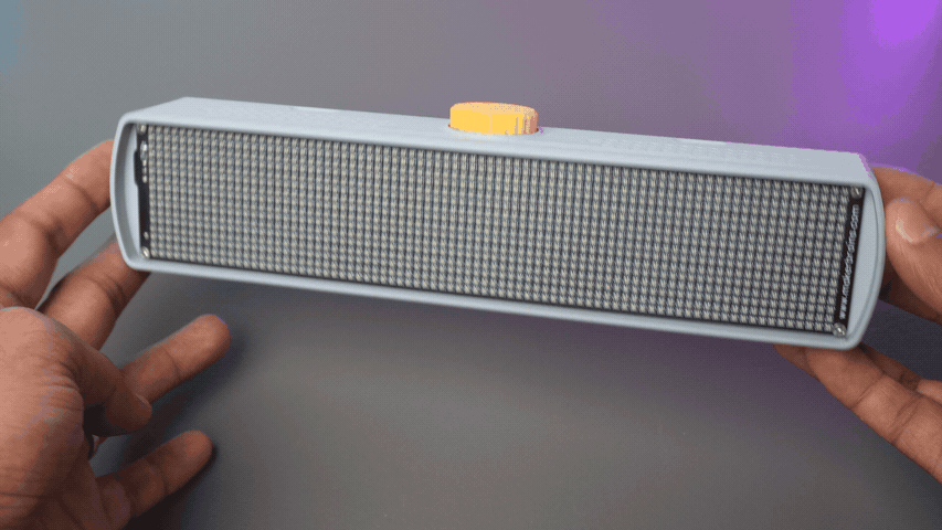
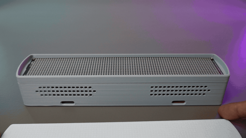
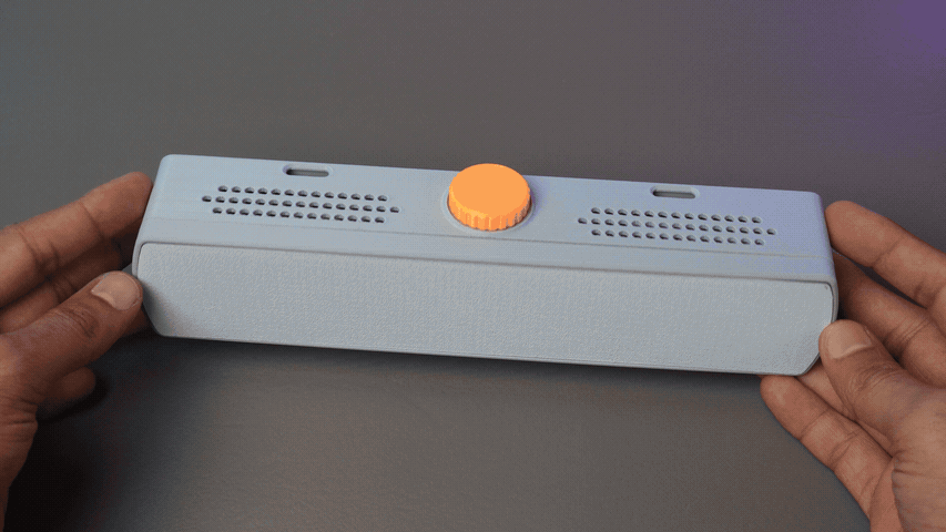
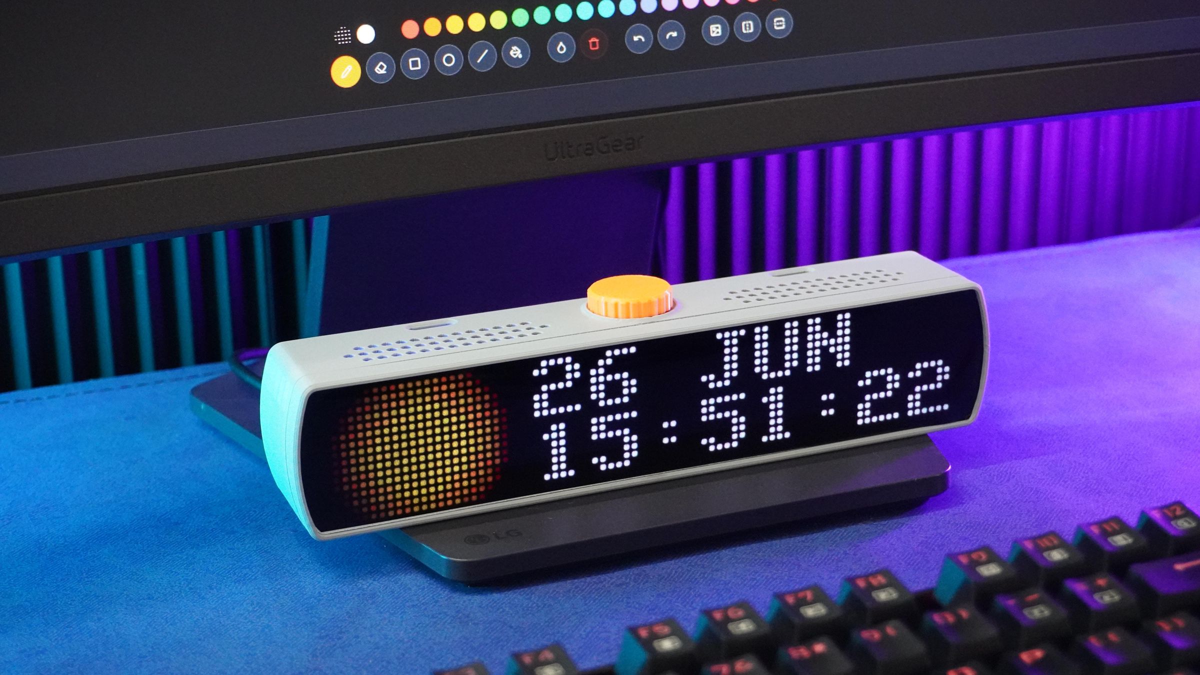
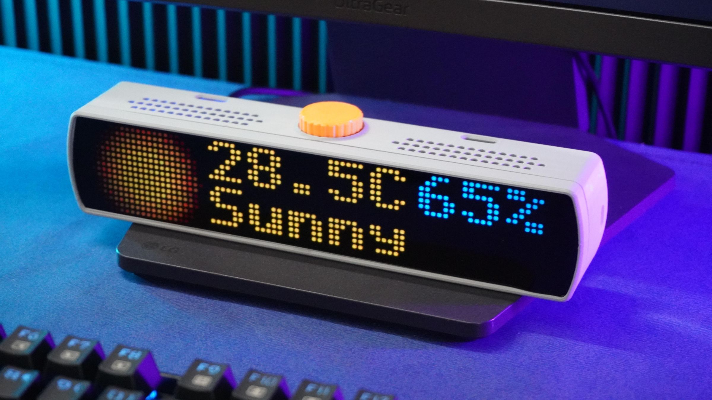
Pixel Bar is an open-source programmable RGB LED display platform designed for makers, developers, and pixel-art enthusiasts. At its core is an 80×16 RGB matrix consisting of 1,280 individually addressable WS2812B-1010 LEDs, driven by a DFRobot FireBeetle 2 ESP32-S3 N16R8.
Unlike conventional LED signboards that are limited to scrolling text and predefined animations, Pixel Bar was designed to be a highly customizable display ecosystem. It combines dedicated hardware, feature-rich firmware, and a browser-based design studio, enabling users to create personalized content and deploy it seamlessly to the device.
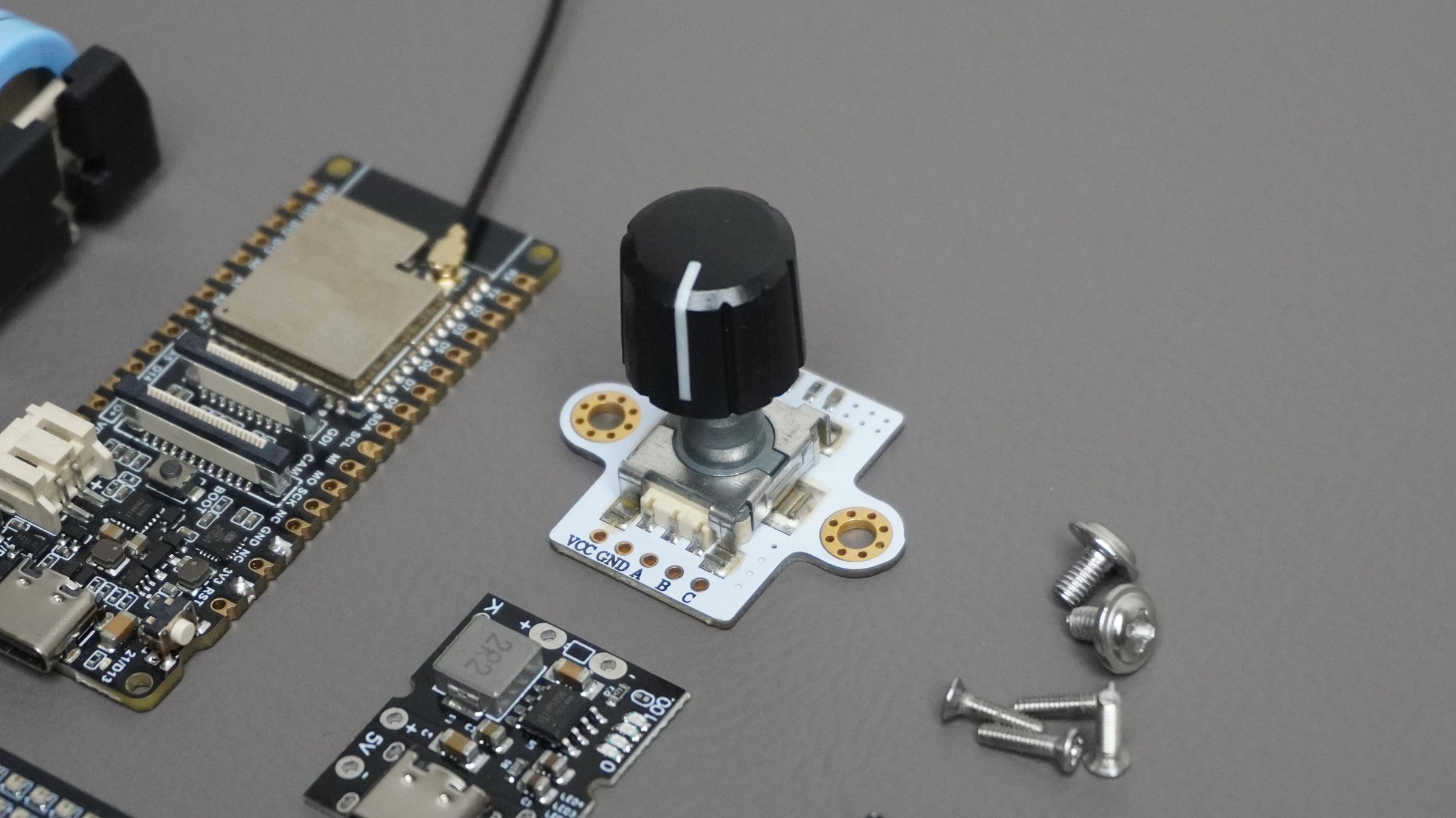
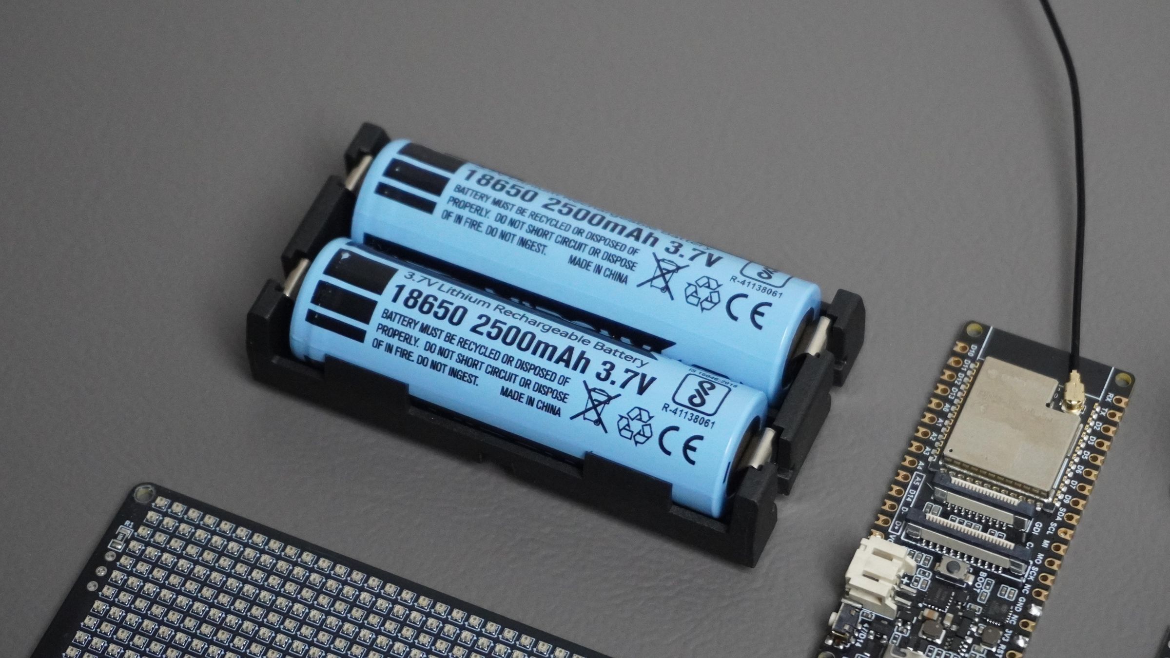
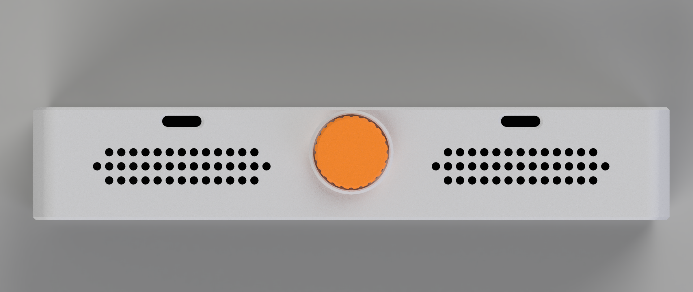
The hardware features a built-in rotary encoder for standalone navigation, allowing users to switch scenes, adjust settings, and interact with the device without relying on a computer or smartphone. Pixel Bar is also completely portable, integrating a rechargeable lithium battery along with a Battery Management System (BMS) for charging, protection, and extended wireless operation.
To complement the hardware, I developed Pixel Studio, a web-based customization environment that provides a complete visual workflow for designing and managing content. Users can create scenes using multiple widgets such as clocks, weather displays, timers, counters, stickers, backgrounds, and animations. The studio supports real-time streaming of content to the physical device, enabling instant previews and rapid iteration.
Pixel Studio also allows users to export scenes as Arduino sketches that can be flashed directly to the ESP32, making it possible to run custom layouts completely offline. Stickers, backgrounds, and animations can be imported and exported as JSON assets or 8-bit PNG images, making content sharing simple and accessible.
To encourage collaboration, Pixel Studio includes a community section where users can publish and discover scenes, stickers, backgrounds, and animations created by other members.
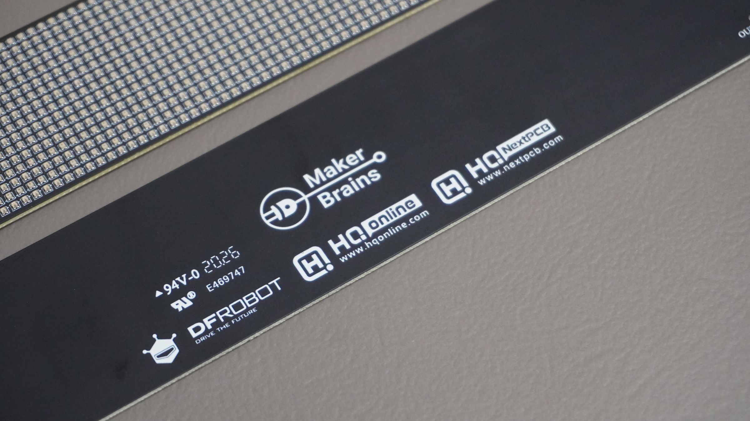
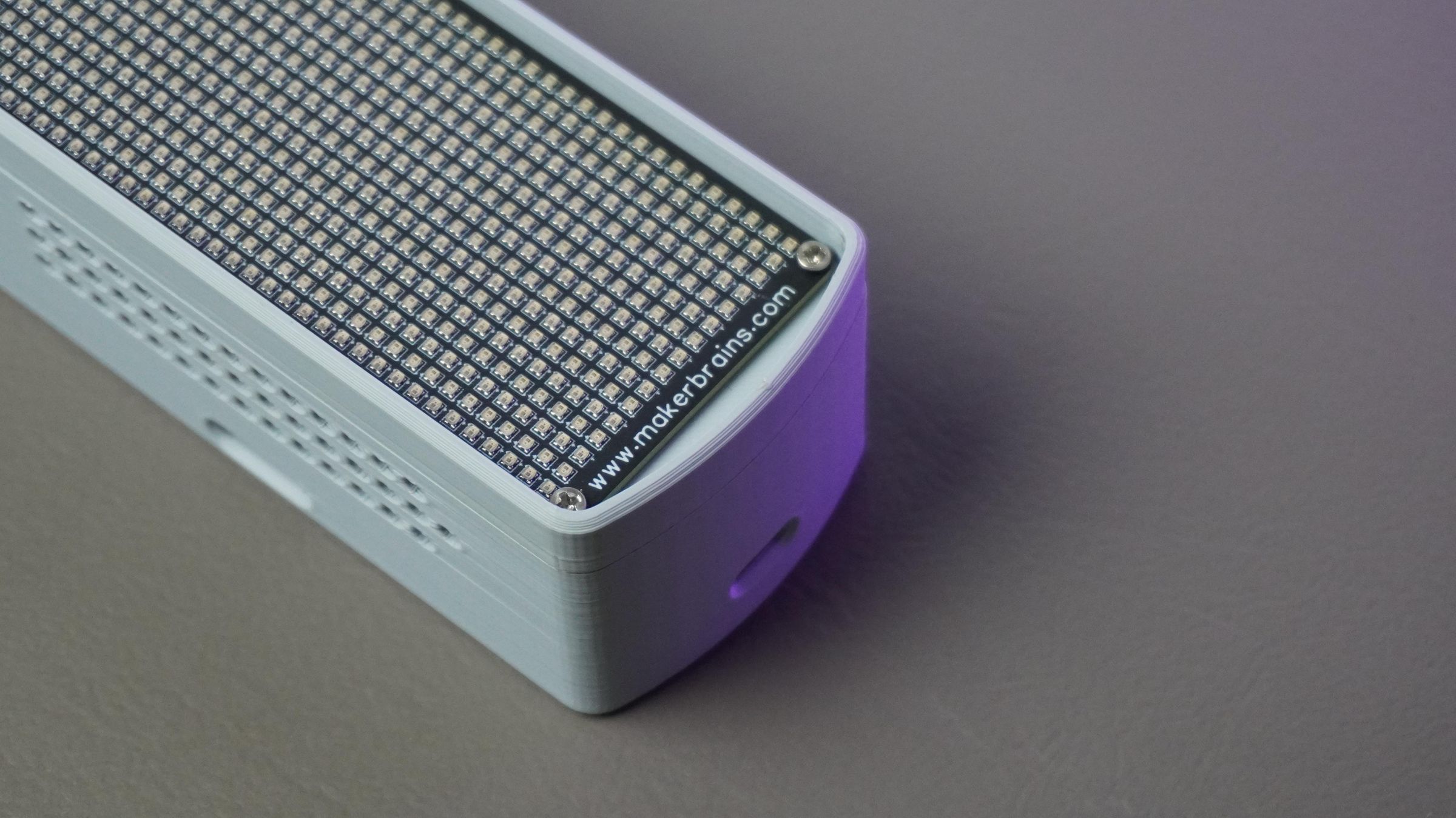
The entire enclosure and mechanical assembly were designed in Fusion 360 and manufactured using 3D printing techniques. The custom PCB was designed specifically for the compact 1010 LED matrix and was manufactured and assembled by NextPCB.
This article covers the complete development process behind Pixel Bar, including hardware design, PCB development, firmware architecture, enclosure design, Pixel Studio, and the lessons learned while building a fully customizable RGB display platform from scratch.
Supplies
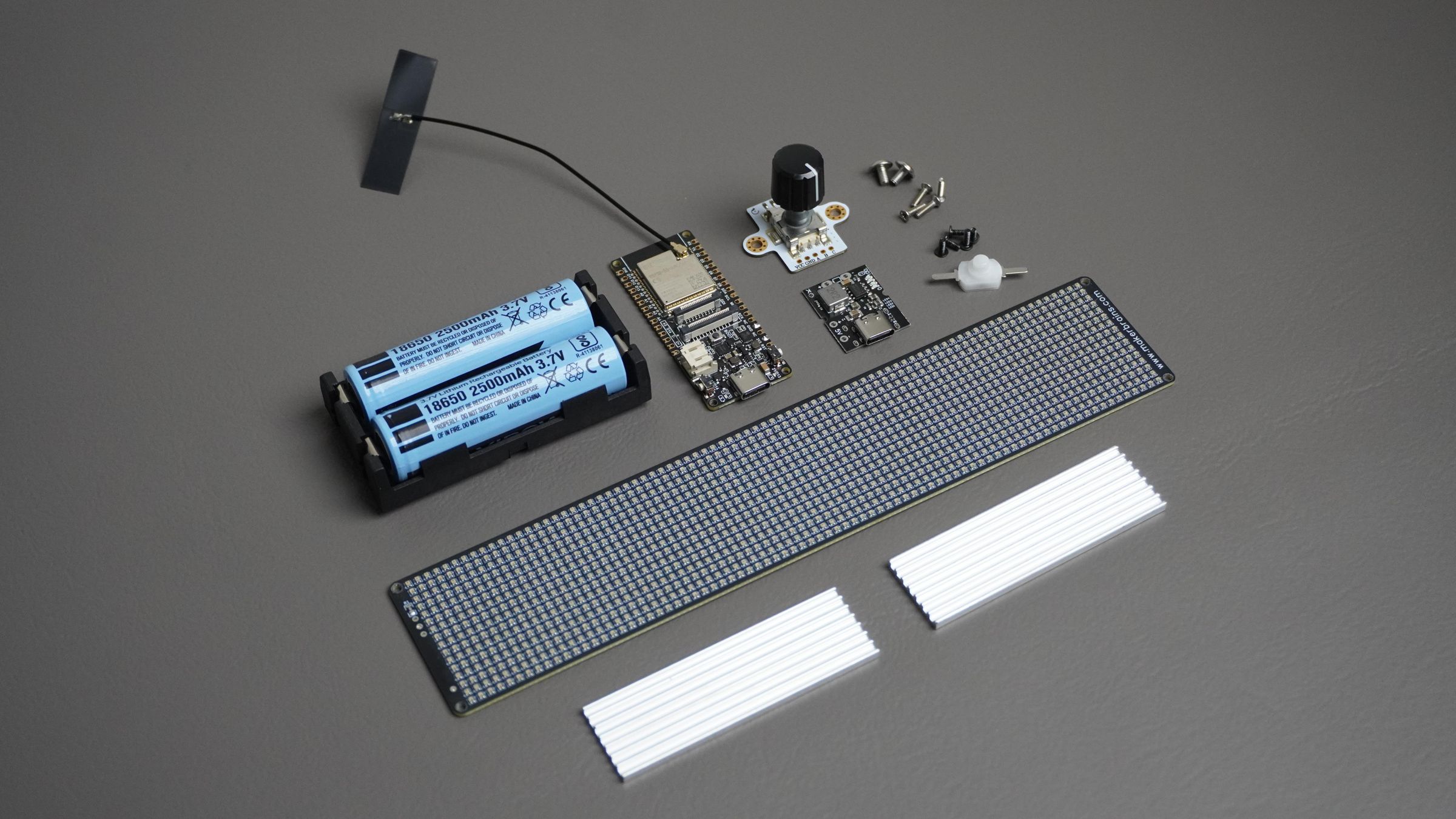
Electronics
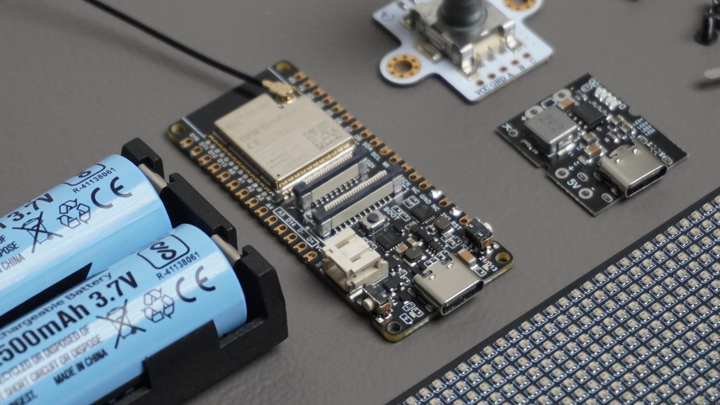
- 1 × DFRobot FireBeetle 2 ESP32-S3 N16R8 Development Board
- 1 × 80 × 16 WS2812B-1010 RGB LED Matrix (1280 LEDs)
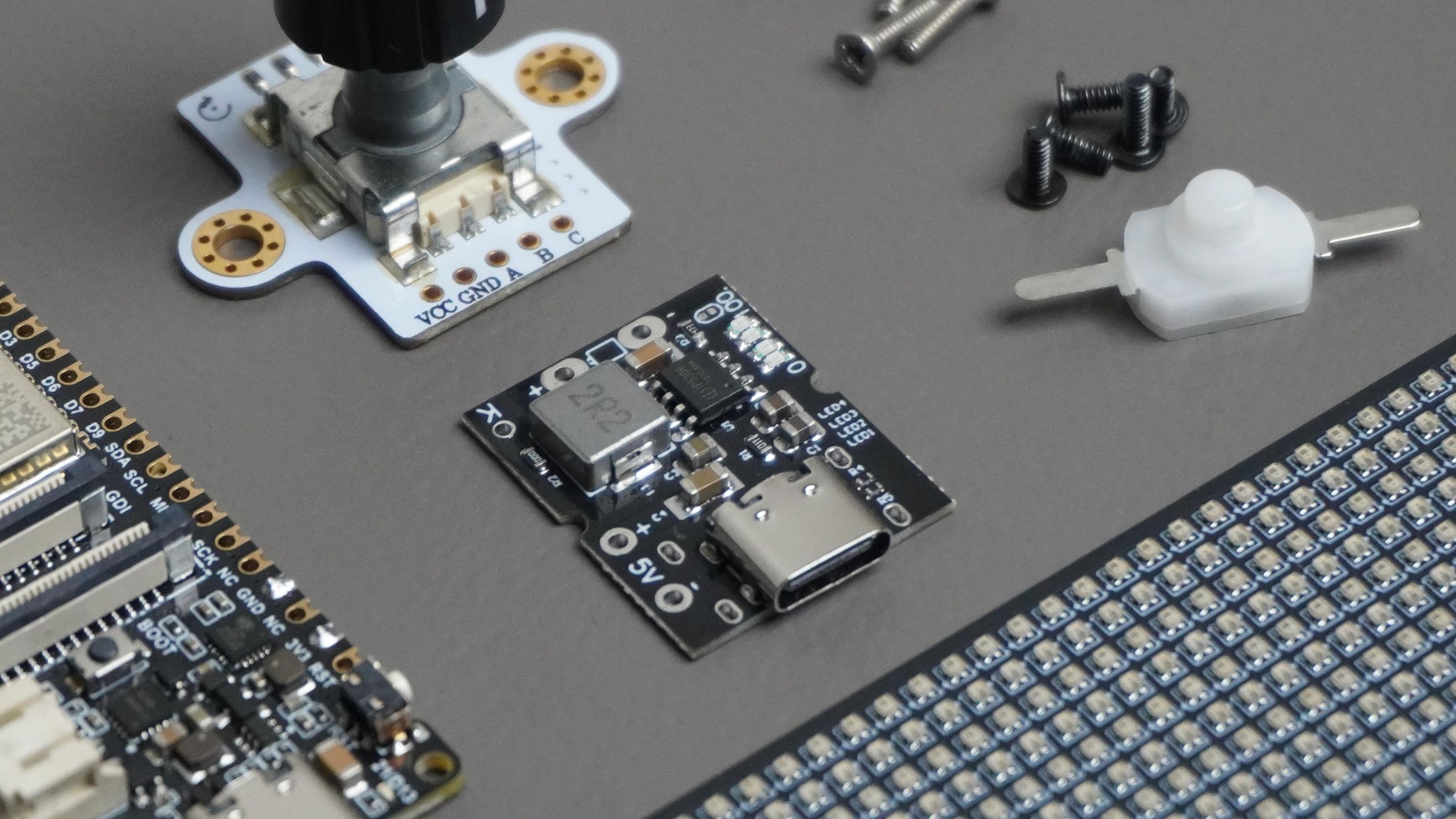
- 1 × Rotary Encoder Module
- 1 × 3.7 V 5200 mAh Lithium Battery Pack
- 1 × Battery Management System (BMS) / Charging & Discharging Module
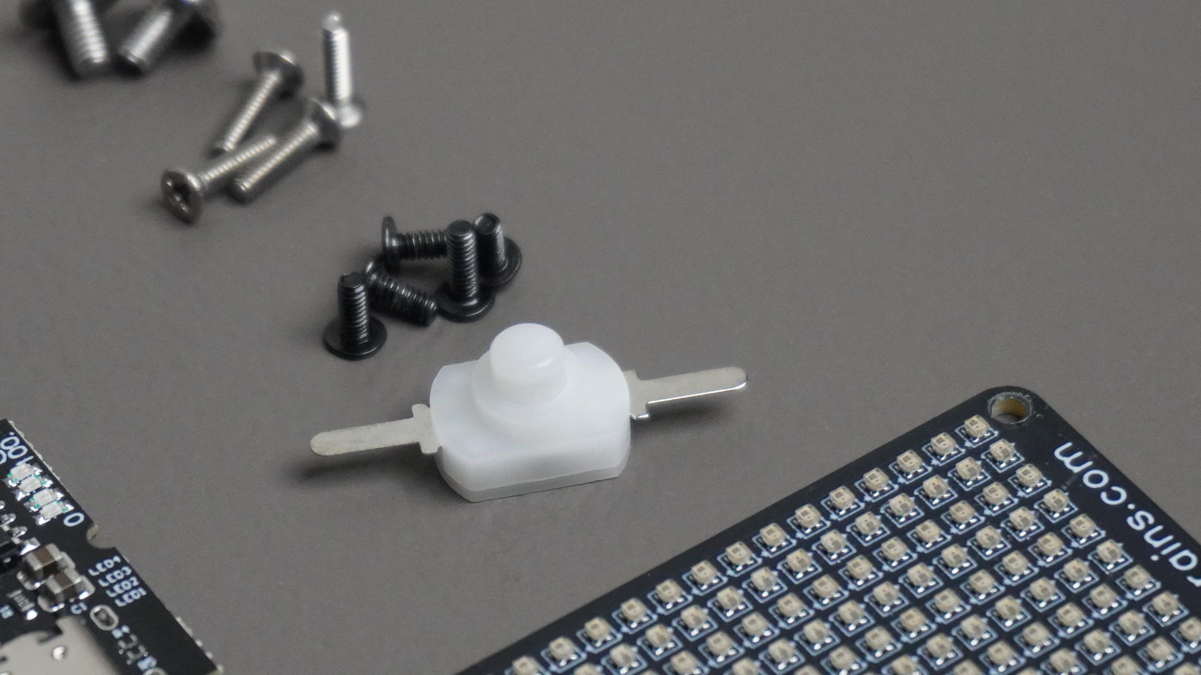
- 1 × Power Switch
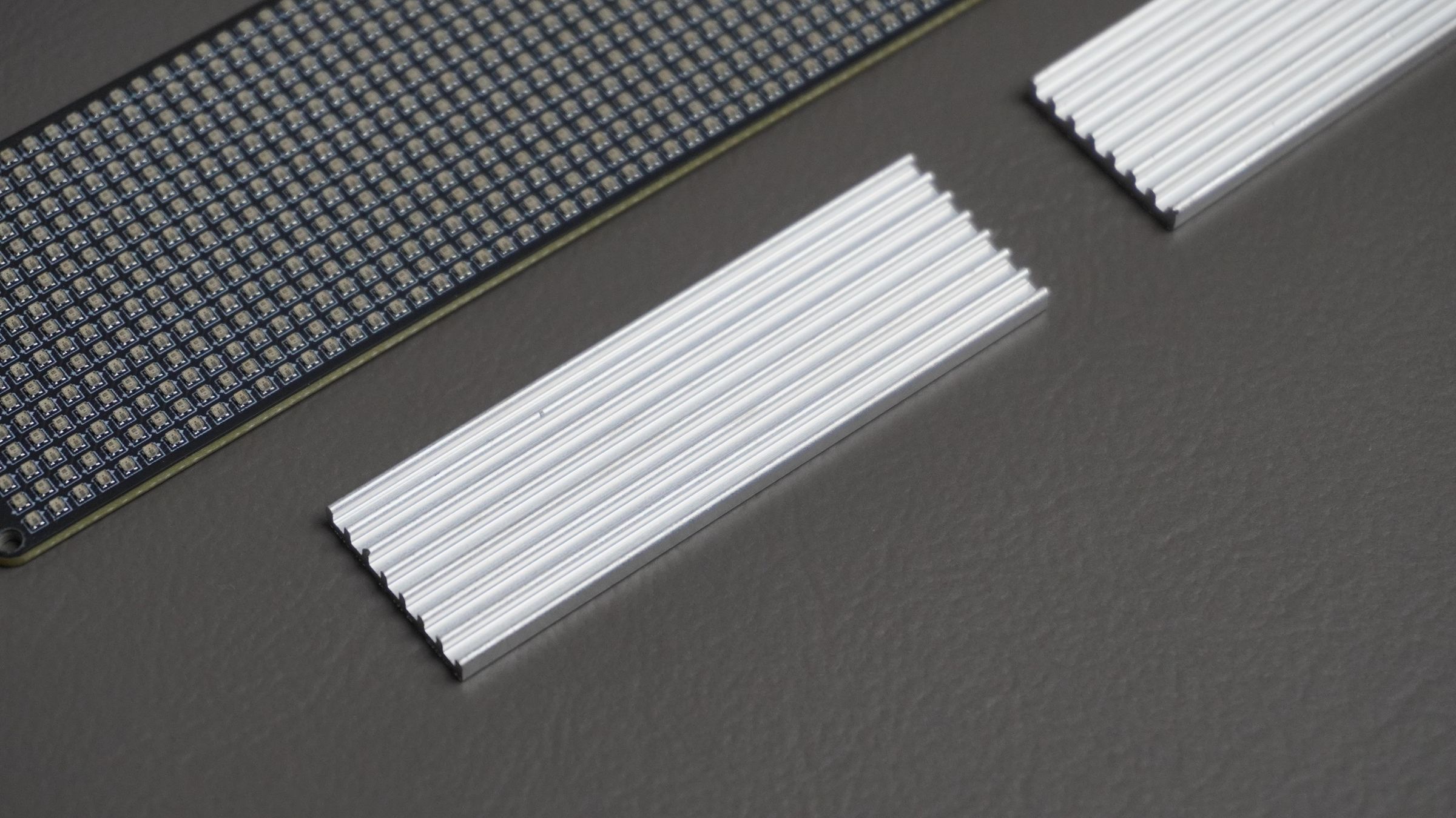
- 2 × Aluminum Heat Sinks
Hardware
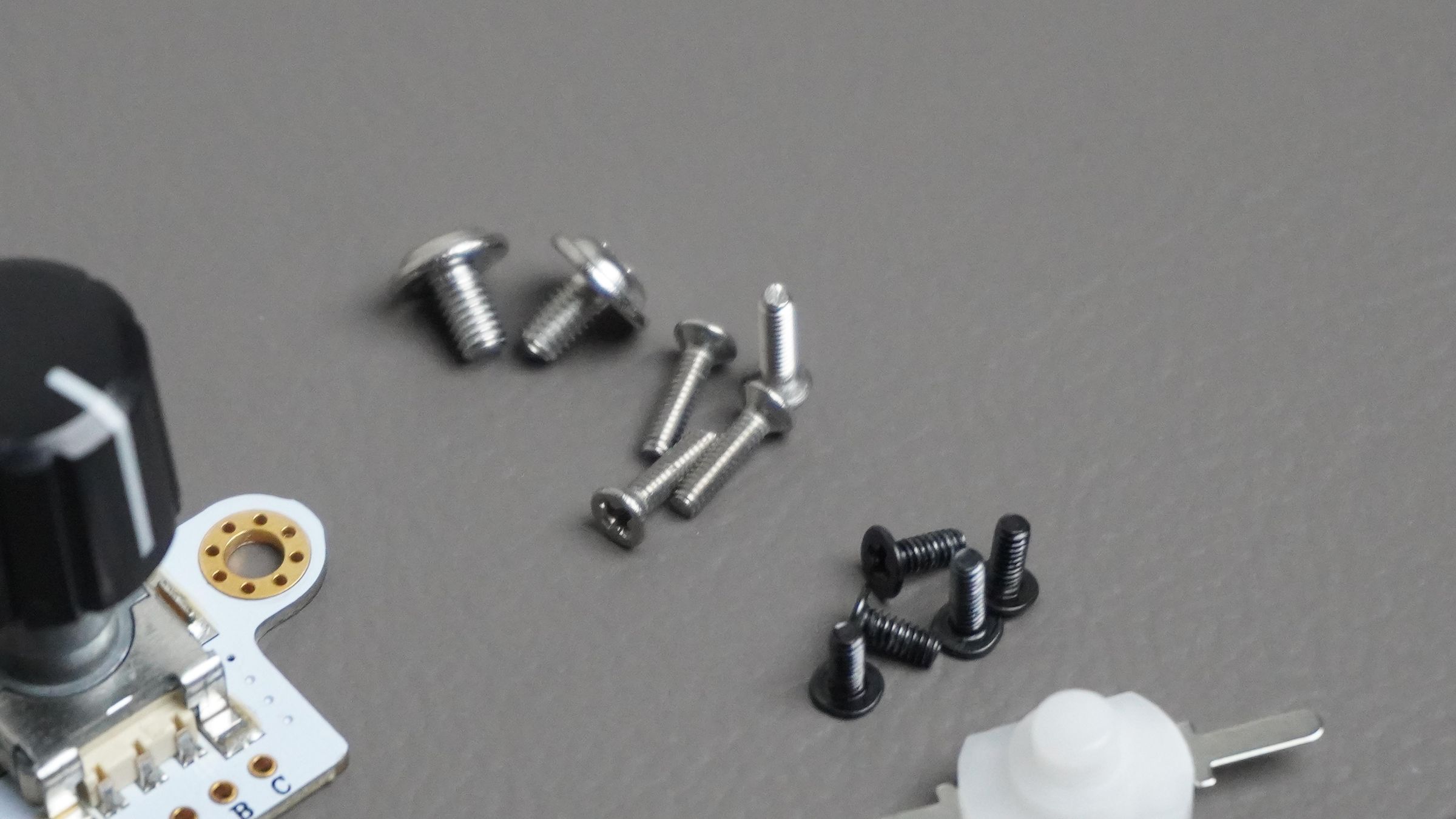
- M2 Screw Assortment Kit
- Screwdriver
Fabrication
- Access to a 3D Printer (or pre-printed enclosure parts)
- PLA, PETG, or ABS filament
Software
- Arduino IDE
- Autodesk Fusion 360 (for enclosure design and modifications)
- Pixel Studio (Browser-based customization software)
Step 1: PCB Design and Manufacturing
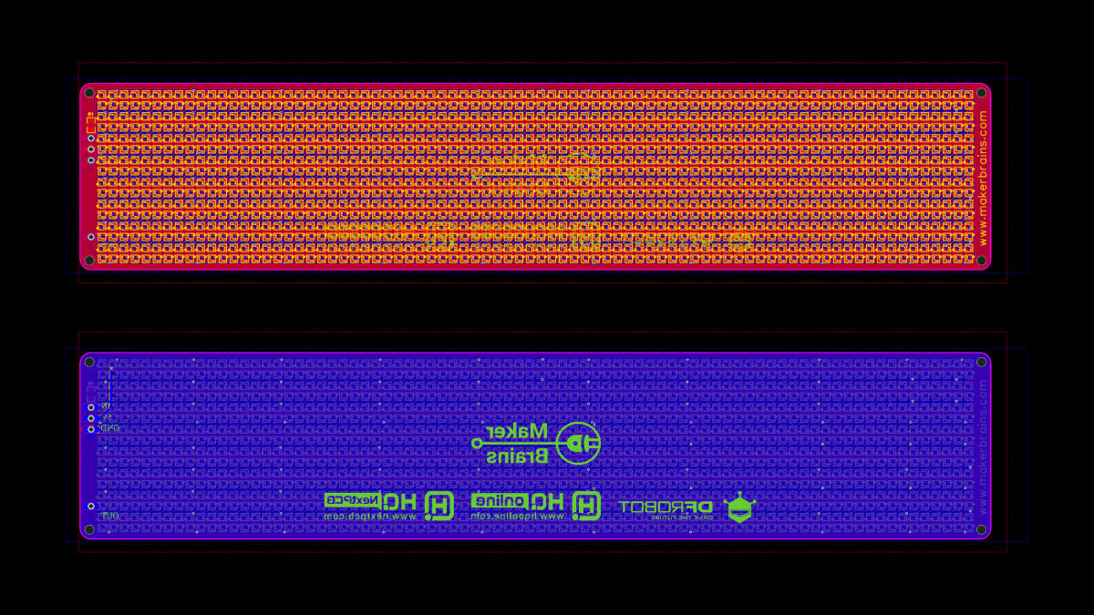
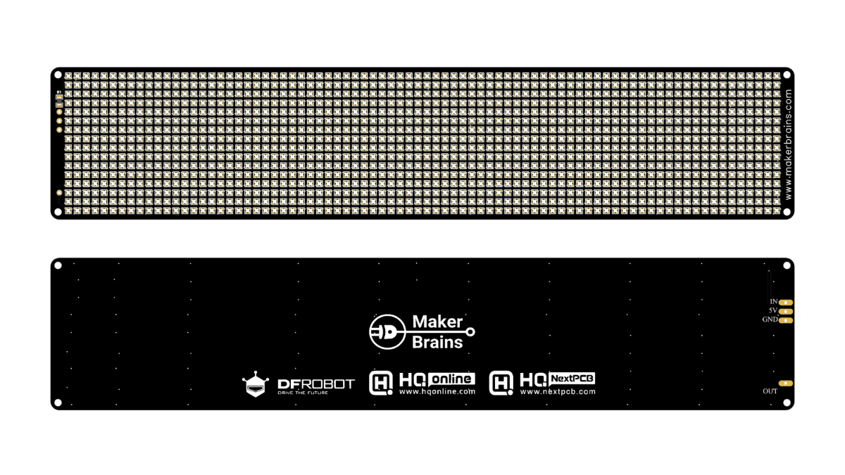
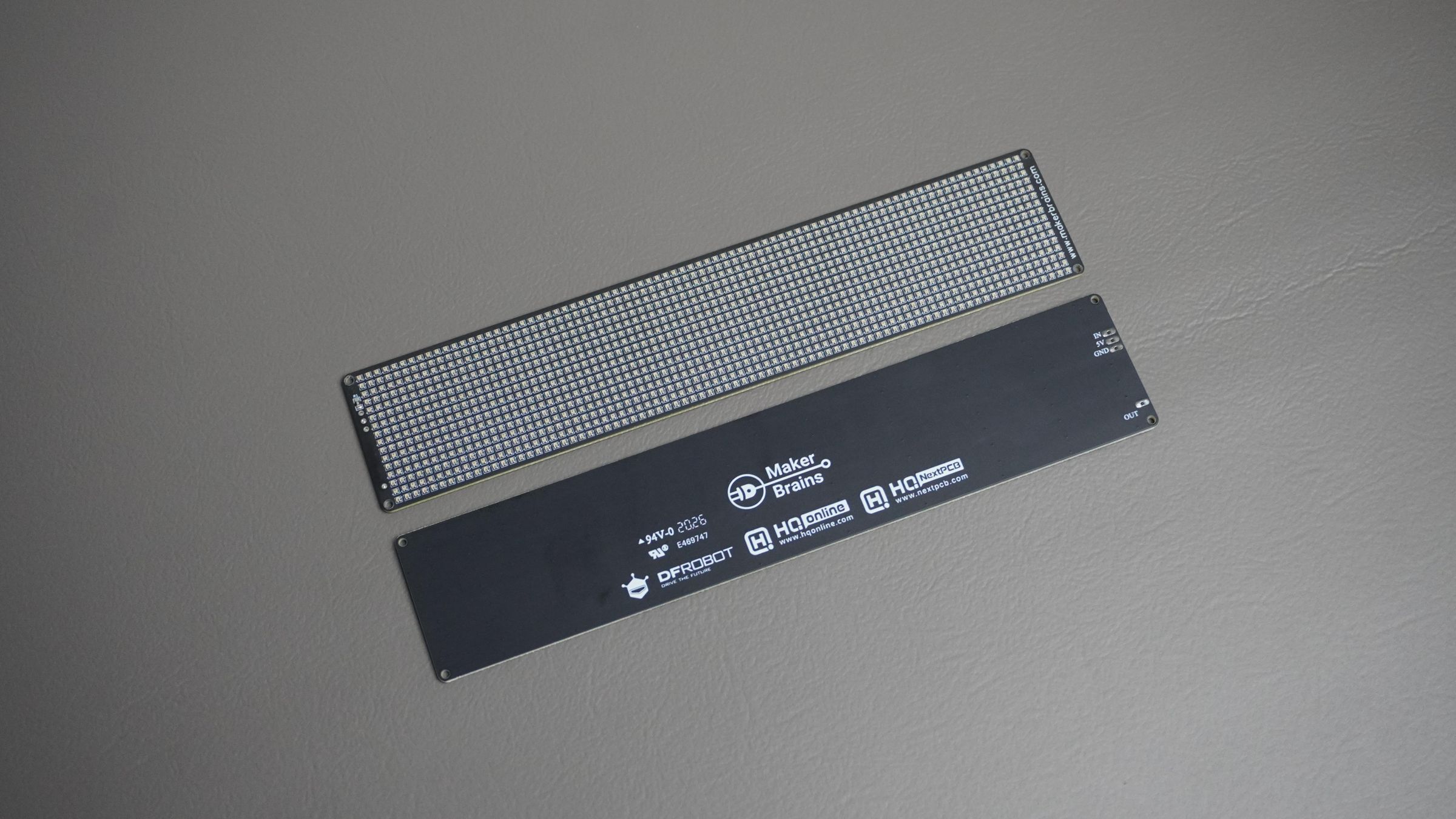
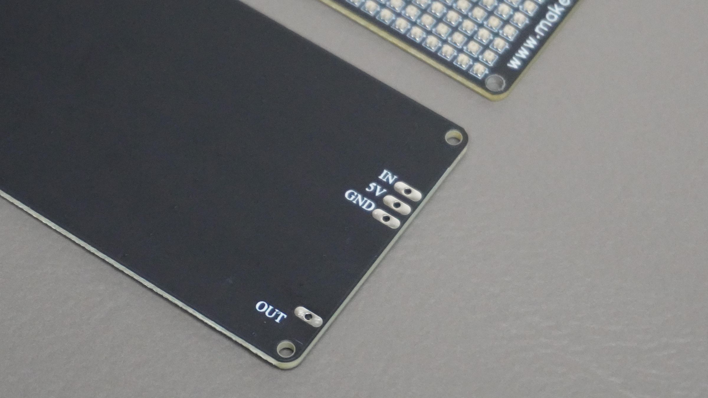
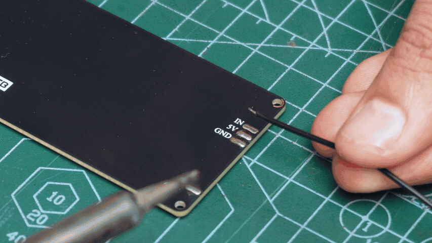
The Pixel Bar uses a custom PCB designed specifically for an 80×16 WS2812B-1010 LED matrix (1280 LEDs). The board itself is intentionally simple and acts as a carrier for the LED matrix, exposing only four connections:
- 5V
- GND
- DIN
- DOUT
The PCB was designed in KiCad and later manufactured and assembled by NextPCB.
After submitting the Gerber files, their engineering team reviewed the design and pointed out a few issues that could affect manufacturing. They coordinated directly with me to resolve these problems before fabrication, which helped avoid costly mistakes and ensured the boards worked perfectly on the first revision.
If you're working on your own PCB projects, I highly recommend checking out NextPCB. Besides PCB fabrication and assembly services, they also offer a very handy Free Online Gerber Viewer. It allows you to visualize Gerber files directly in your browser and run built-in Design for Manufacture (DFM) checks to identify potential fabrication issues before placing an order.
The viewer supports:
- Gerber RS-274X
- Gerber X2
- Excellon drill files
- ODB++
- Native KiCad PCB files (.kicad_pcb)
This is especially useful for quickly verifying silkscreen alignment, drill placements, board outlines, and other manufacturing details without installing additional software.
Useful Links
• NextPCB PCB Manufacturing & Assembly
• Components used for the assembly were sourced through HQComponents.
• Free Online Gerber Viewer and DFM Checker
https://www.nextpcb.com/free-online-gerber-viewer.html
For anyone interested in building their own Pixel Bar, I have included the following design files:
Step 2: CAD Designing
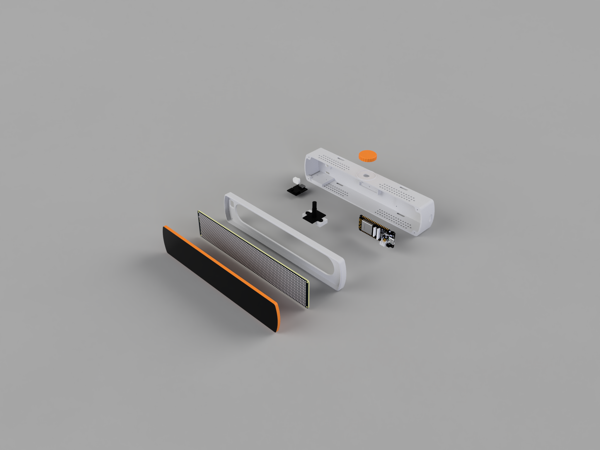
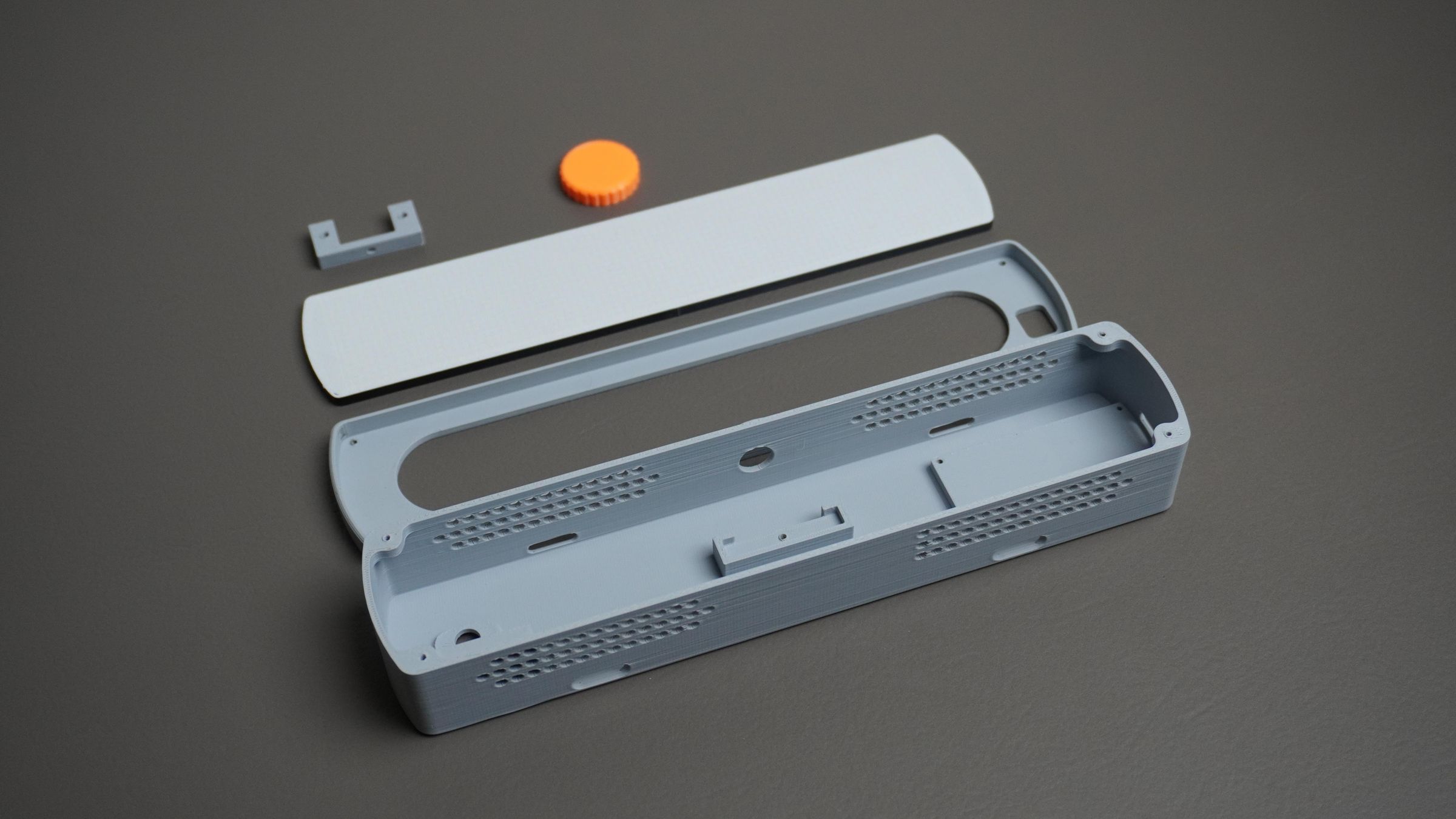
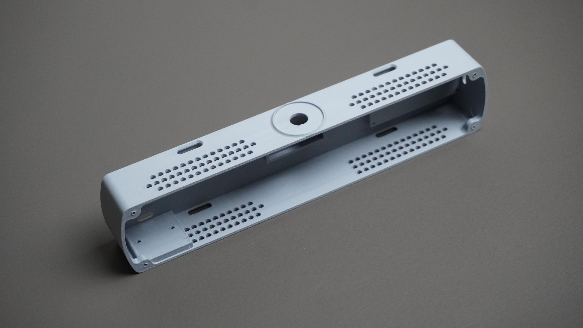
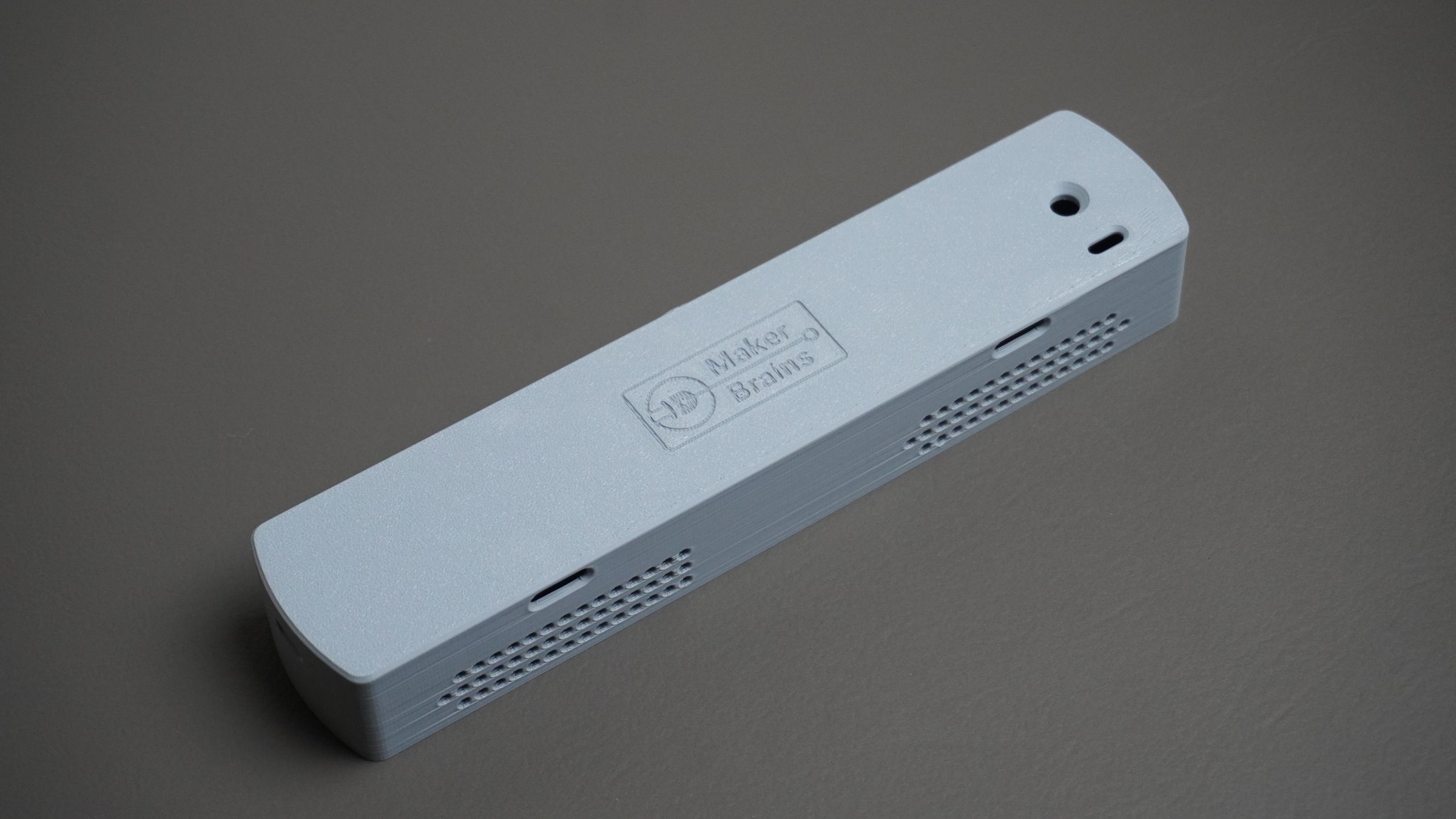
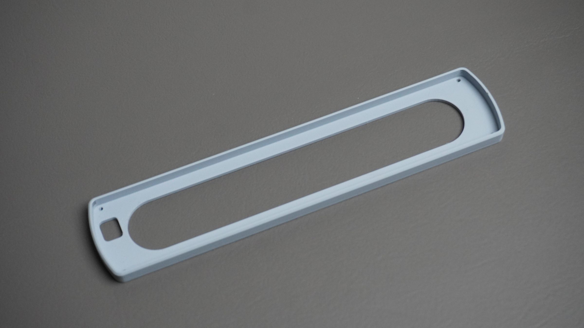
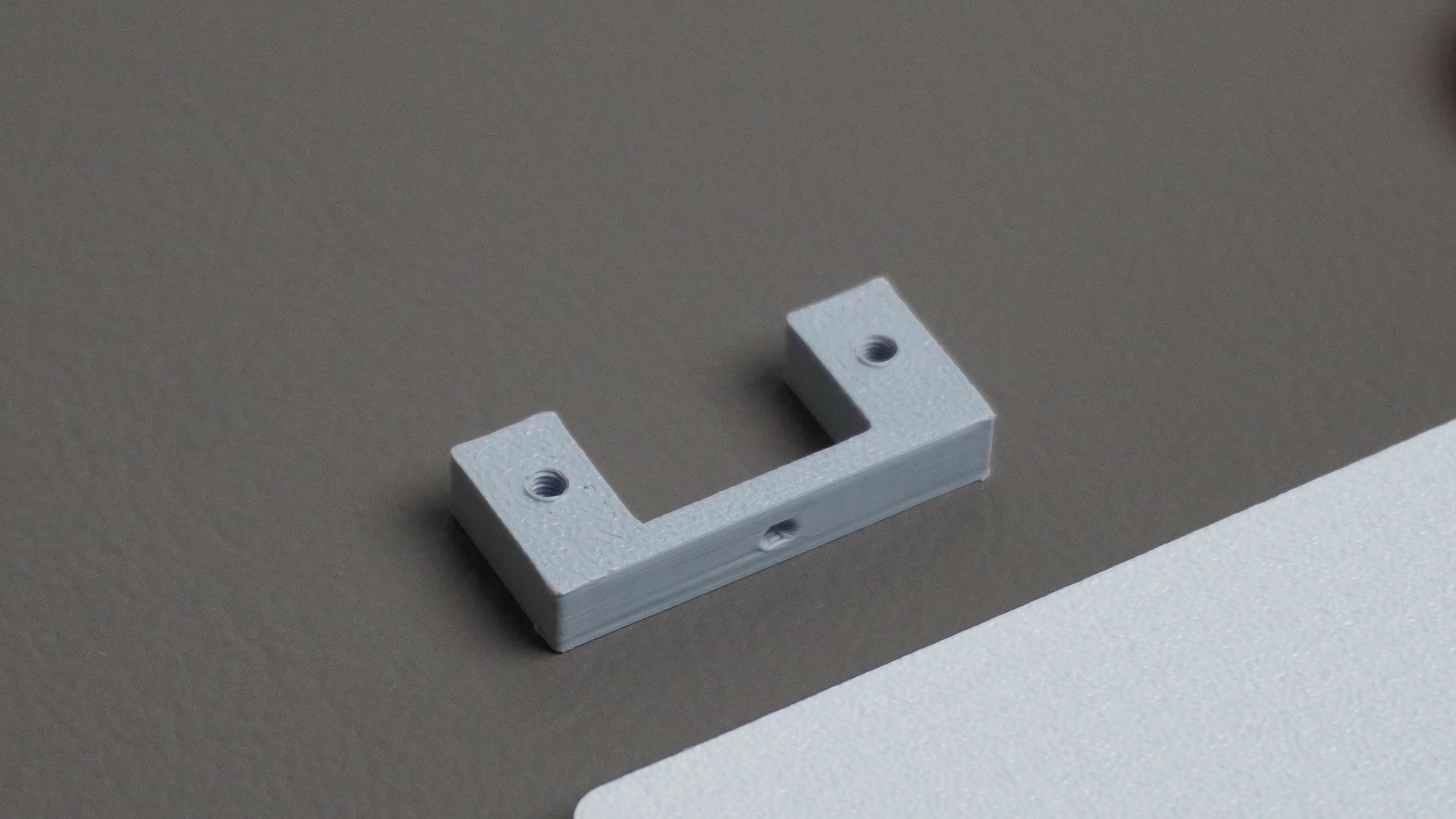
The enclosure was designed in Fusion 360 and consists of five 3D printable parts.
Housing:
- This is the main body of the Pixel Bar. It includes mounting points for the BMS module, ESP32, rotary encoder, and power switch. It also has dedicated Type-C cutouts for both the ESP32 and charging module, along with space to fit the 5200mAh battery pack.
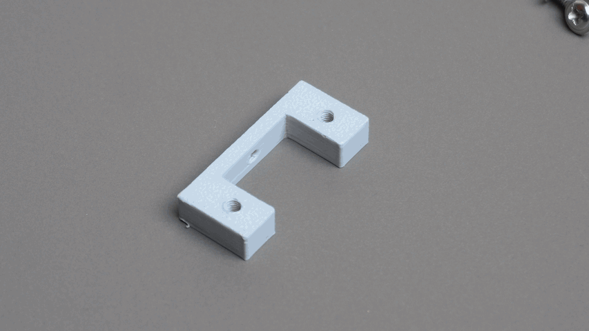
Encoder Mount:
- A small bracket used to securely mount the rotary encoder to the housing.
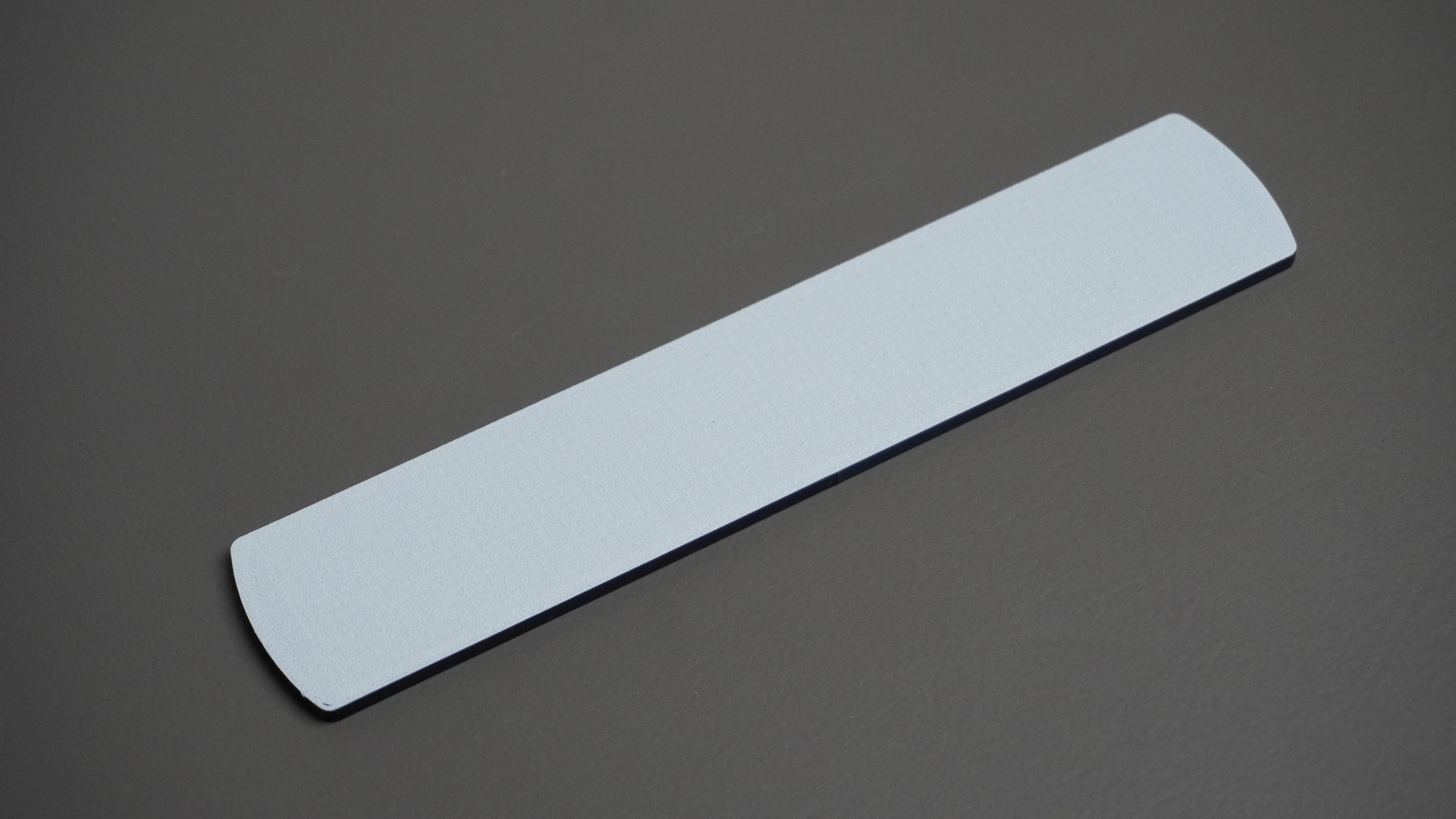
Front Mount:
- This part holds the LED matrix PCB in place and attaches to the housing.
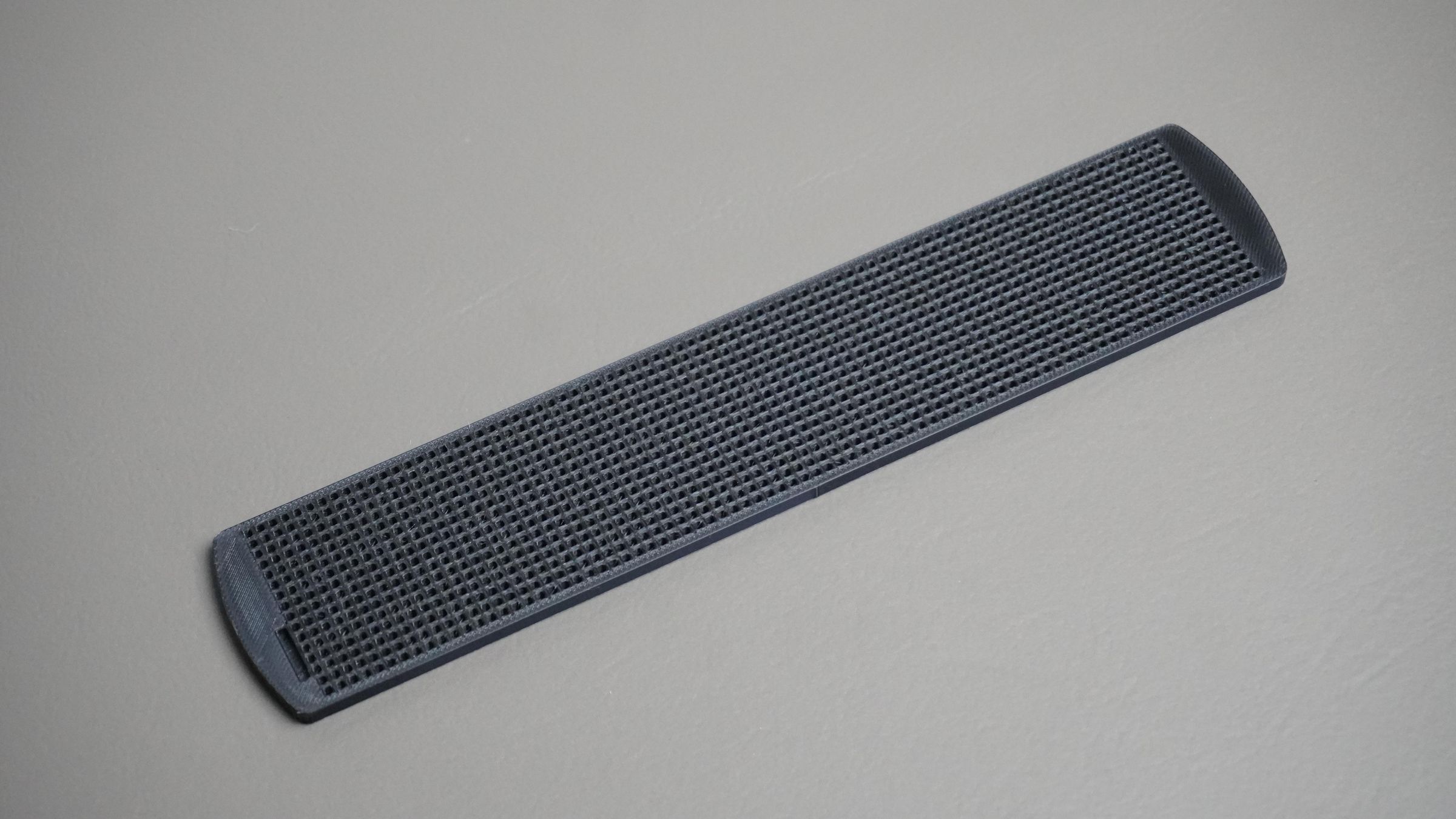
Grid:
- The grid sits on top of the LED matrix PCB and separates individual LEDs, improving contrast while also acting as a diffuser. It fits snugly inside the front mount.
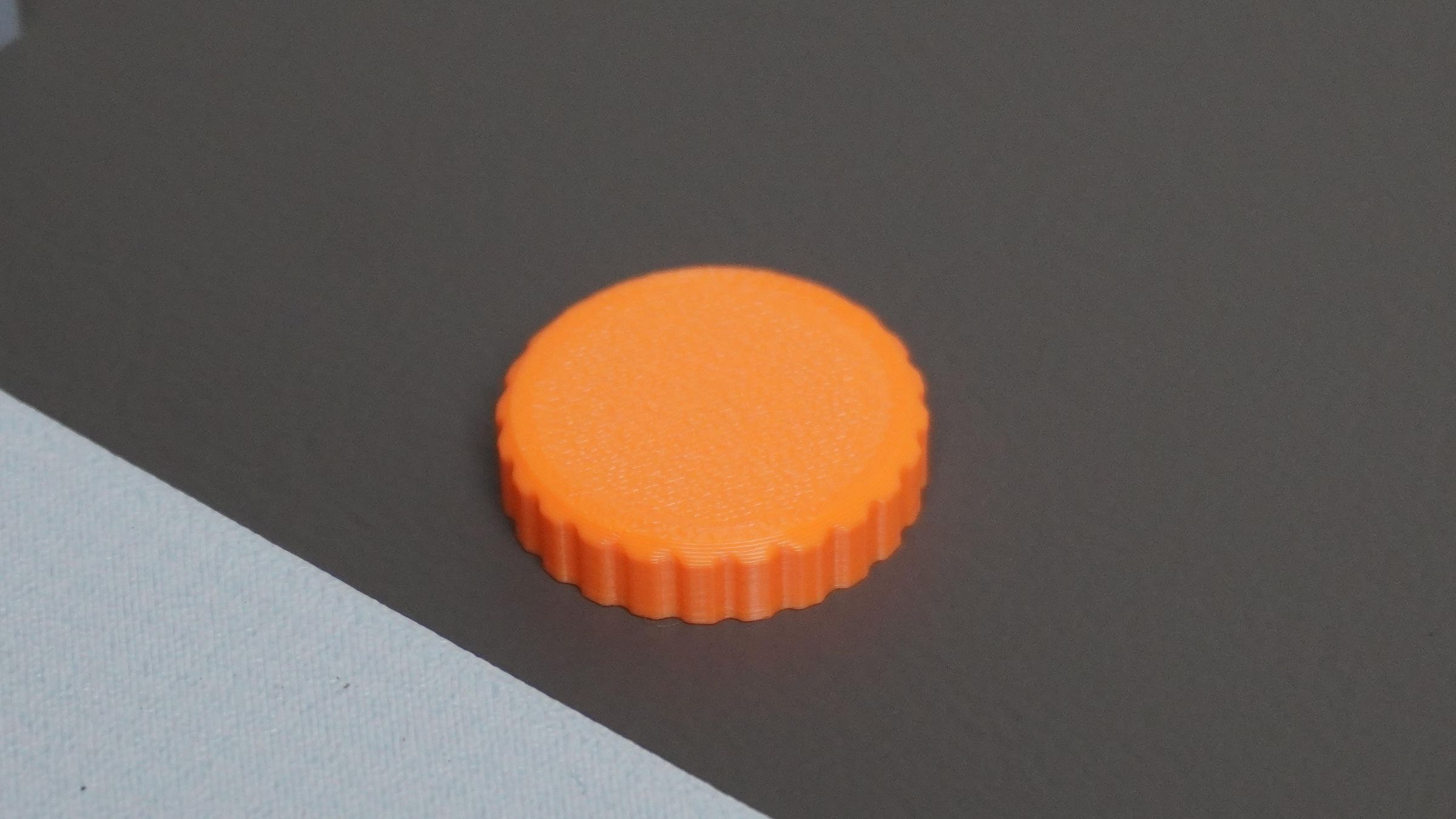
Knob:
- A simple 3D printed knob designed specifically for the rotary encoder.
All design files, including the Fusion 360 source and STL files, are provided in the attachments for anyone who wants to modify or 3D Print the enclosure.
Step 3: 3D Printing
Once the CAD design was finalized, I 3D printed all five parts of the enclosure.
For the main enclosure pieces, I used Light Gray PLA:
- Housing
- Encoder Mount
- Front Mount
The encoder knob was printed in Orange PLA to add a bit of contrast.
For the Grid, I wanted white diffuser walls with black separators to improve the display appearance. To achieve this, I started the print with White PLA, printed the first layer, then paused the printer and switched to Black PLA for the remaining layers.
This simple filament swap creates a grid with a white base for better light diffusion and black walls that help isolate individual pixels and enhance contrast.
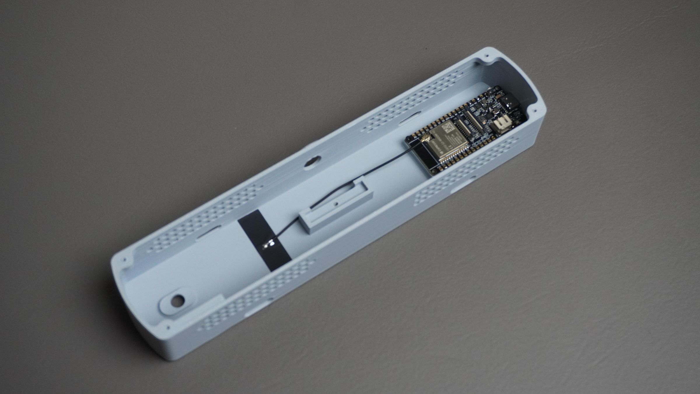
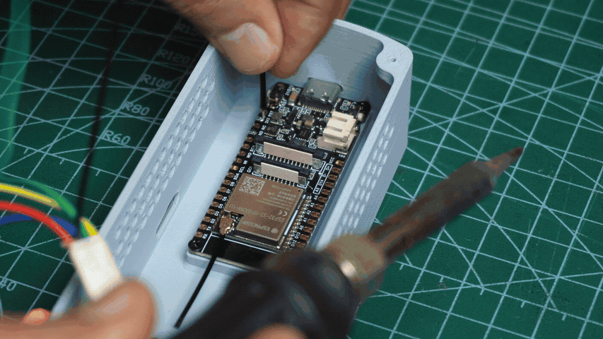
Step 4: Mounting the ESP32-S3
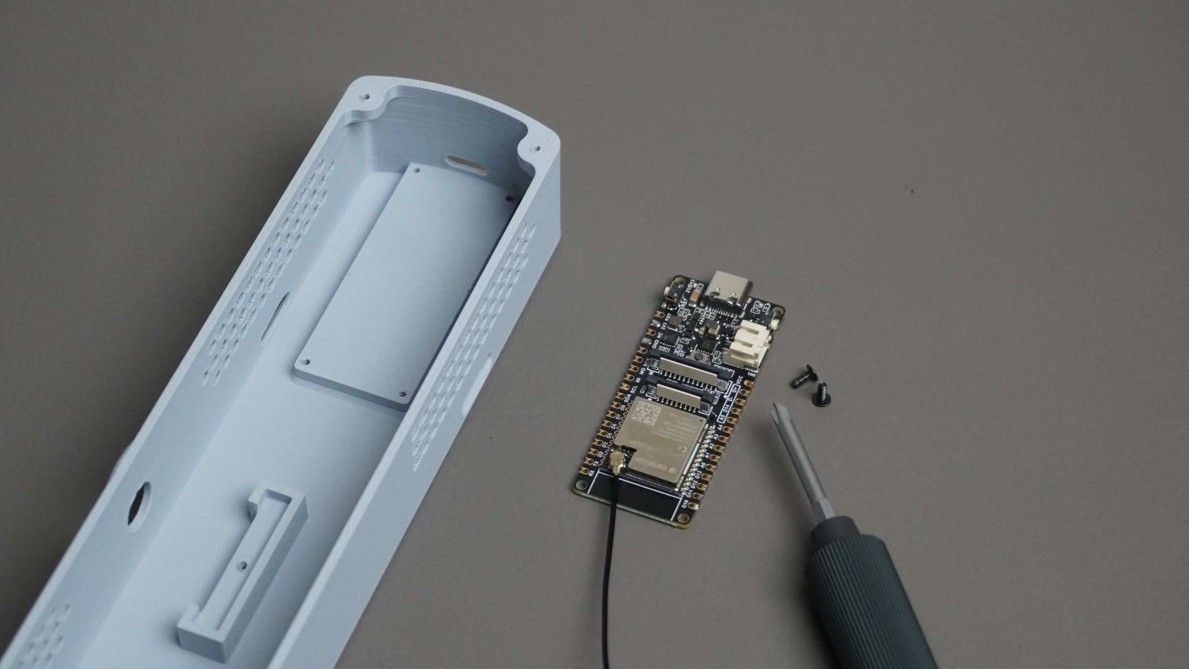
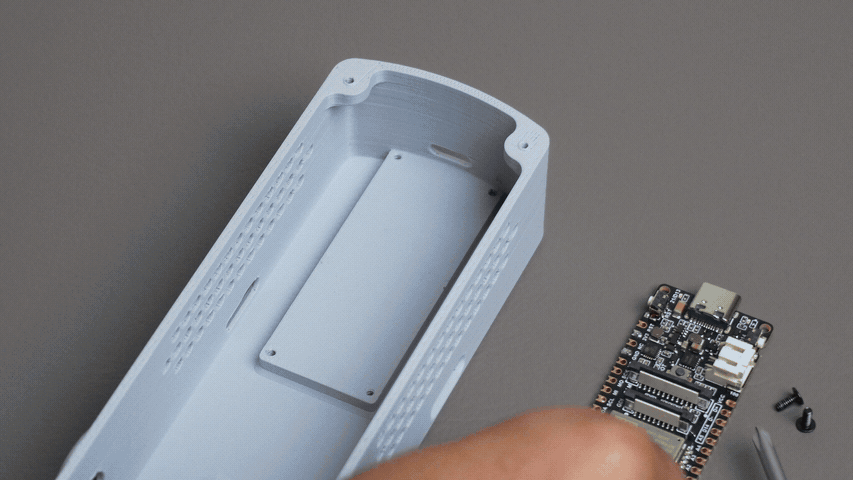
Take the FireBeetle 2 ESP32-S3 and the Housing part. Align the board with the mounting holes and the USB Type-C cutout.
Secure the ESP32 in place using two M2 × 6 mm screws.
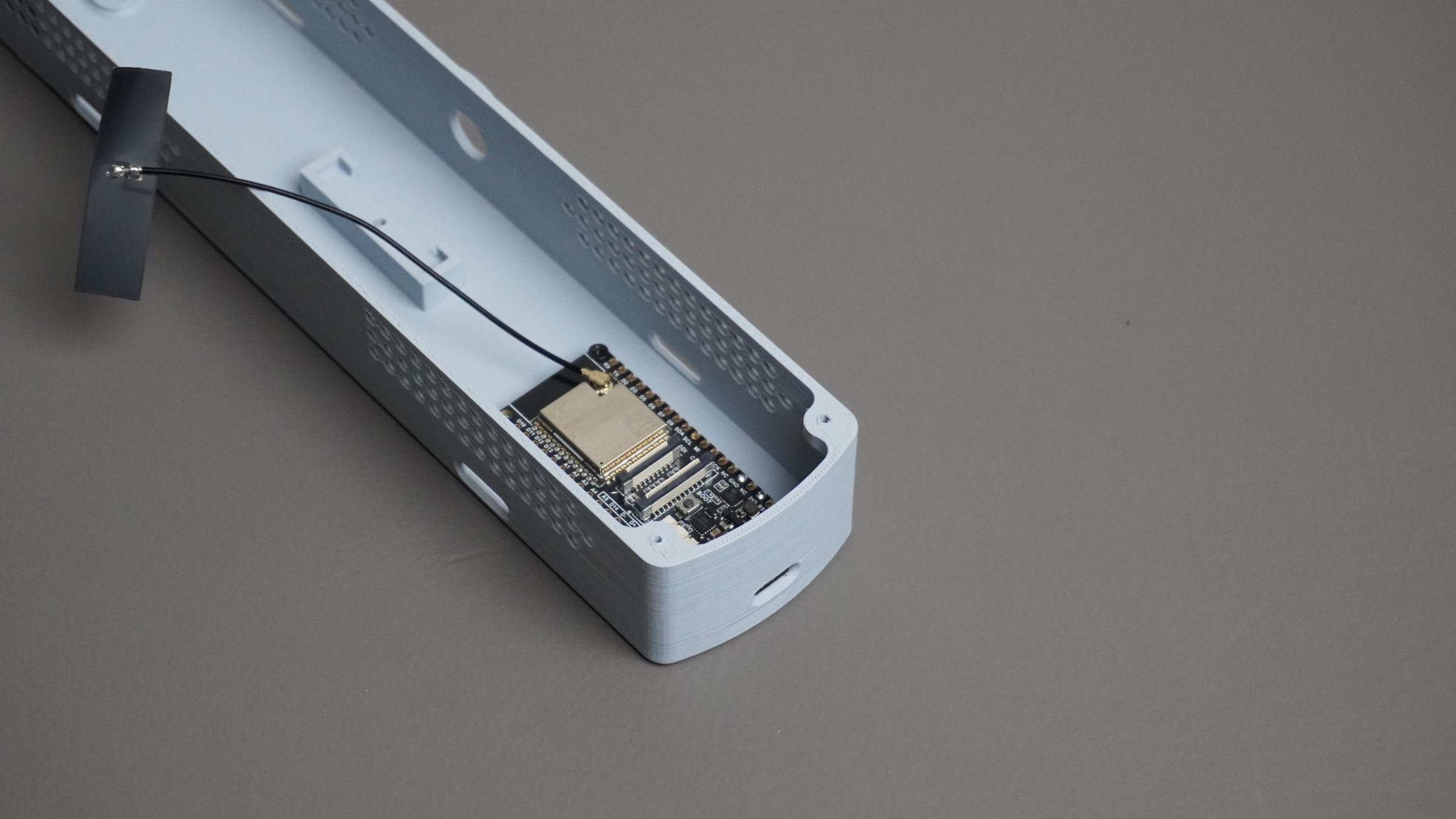
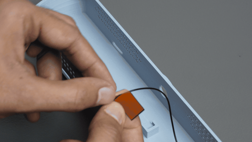
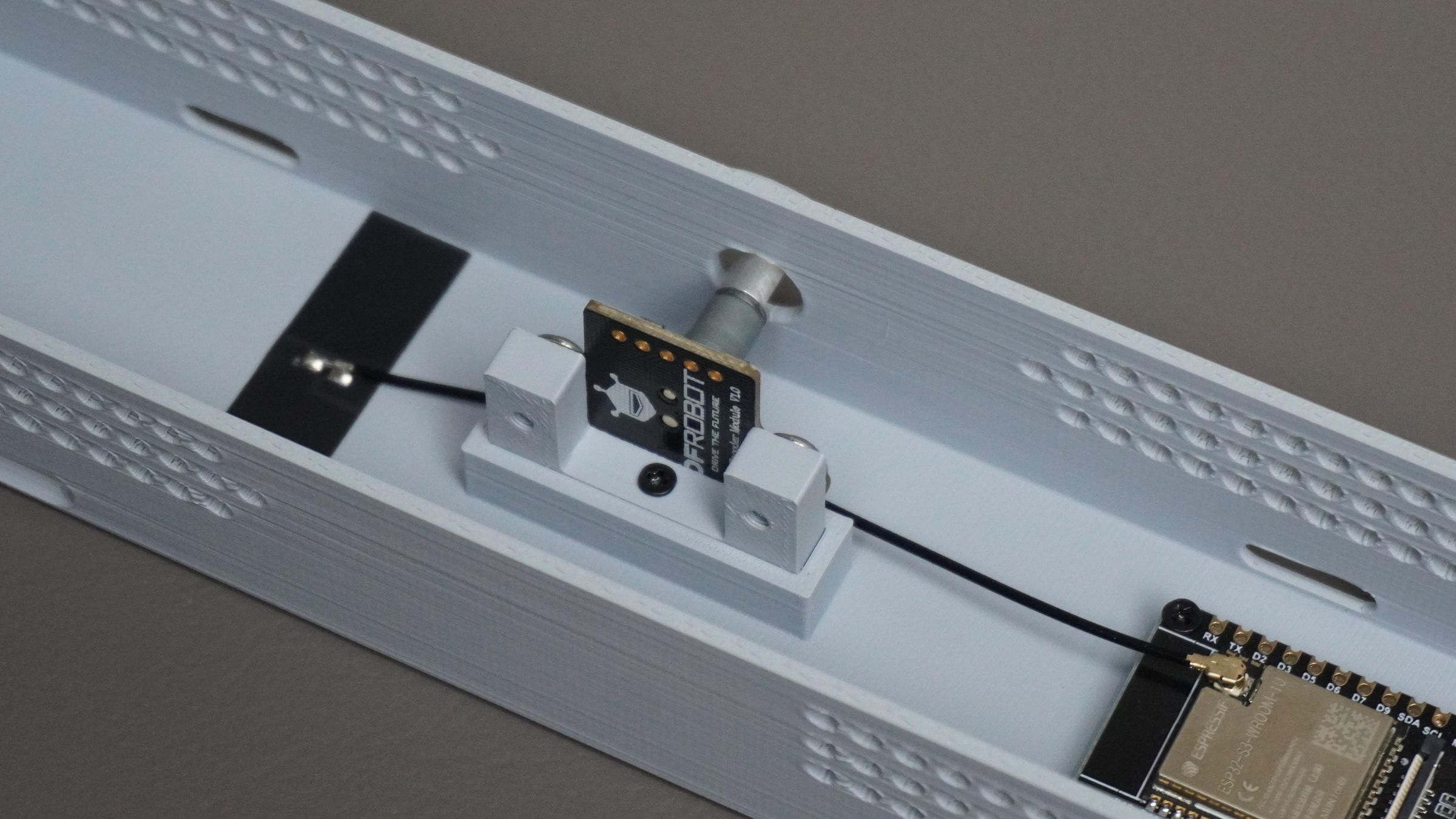
Next, take the external antenna supplied with the ESP32 and connect it to the U.FL connector on the board. Peel off the adhesive backing from the antenna and stick it inside the housing.
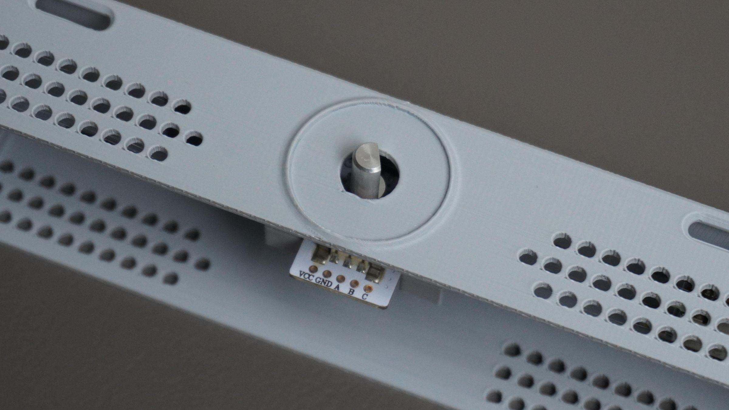
Step 5: Mounting the Encoder
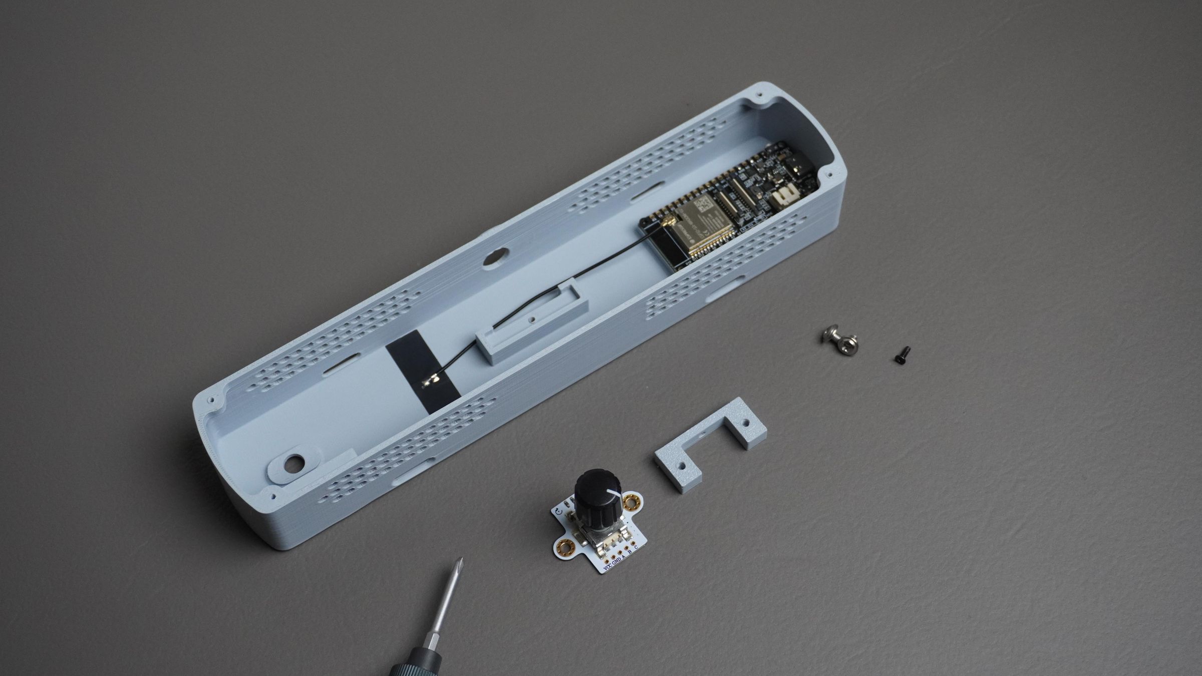
Take the Encoder Mount and the rotary encoder. Align the encoder with the mounting holes on the bracket and secure it using two M3 screws.
Next, place the assembled encoder bracket into its designated slot in the Housing and fasten it with one M2 screw.
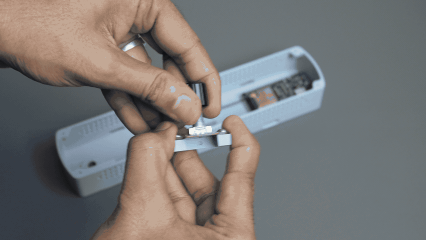
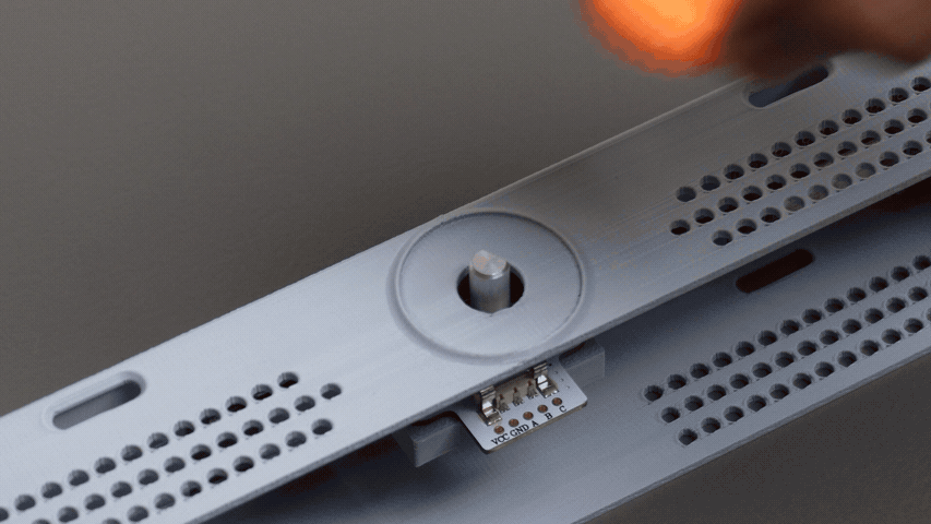
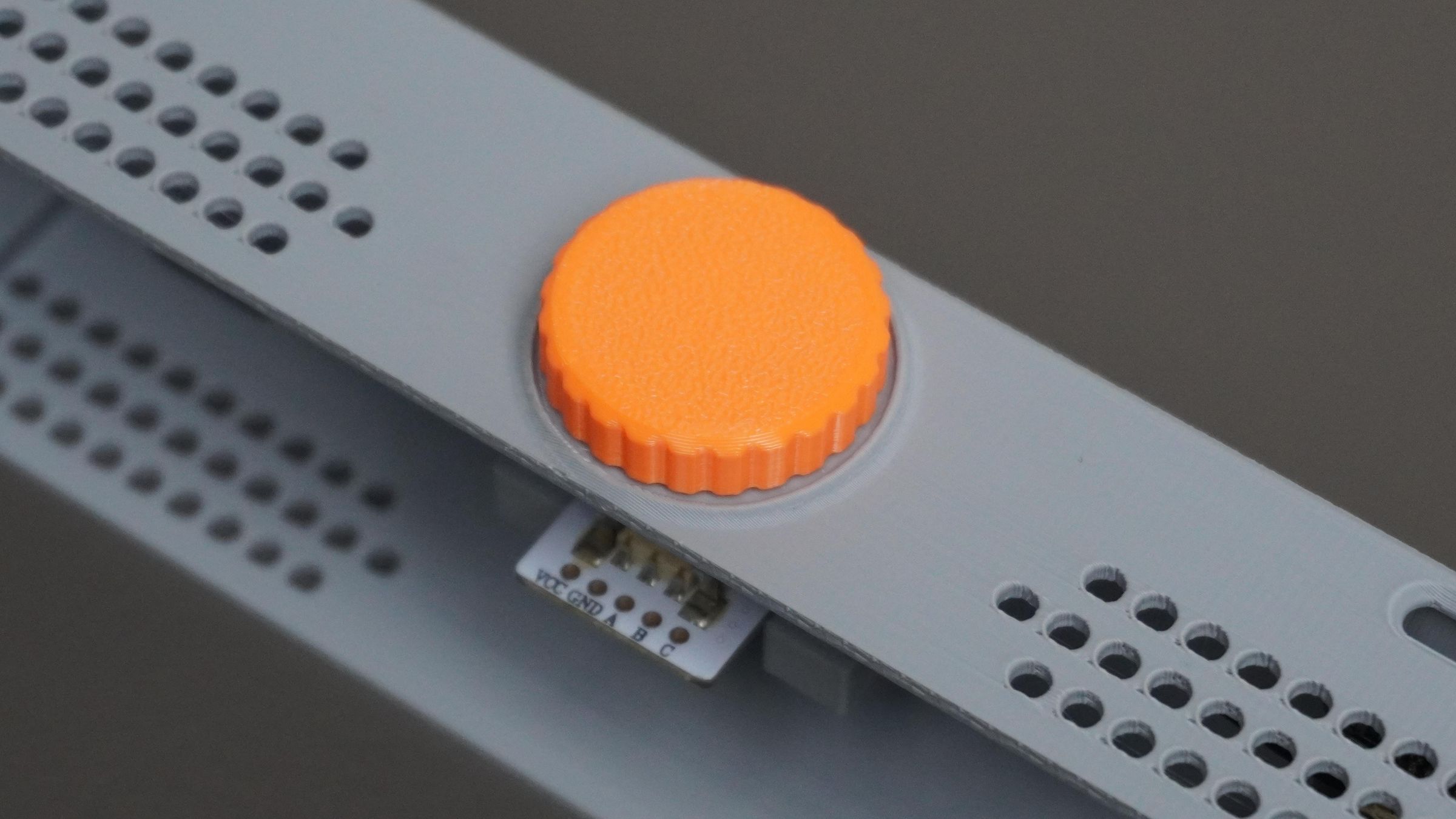
Step 6: Installing the Encoder Knob
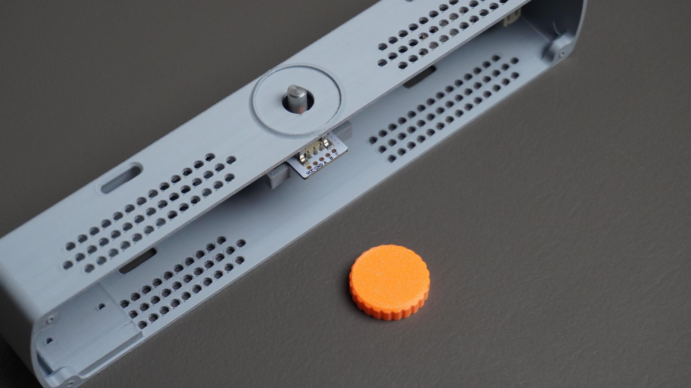 Take the 3D printed knob and simply press it onto the encoder shaft protruding from the top of the housing.
Push it down firmly until it sits snugly in place. The friction fit should hold the knob securely without the need for any additional hardware.
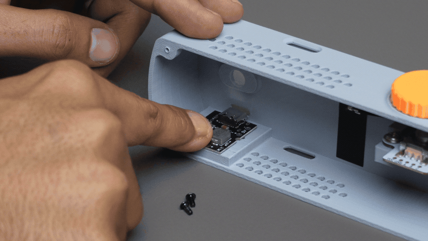
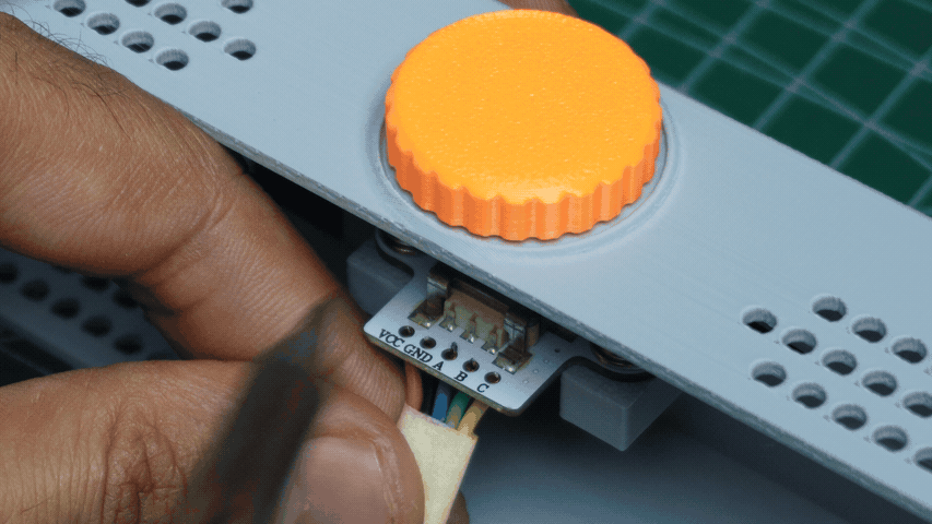
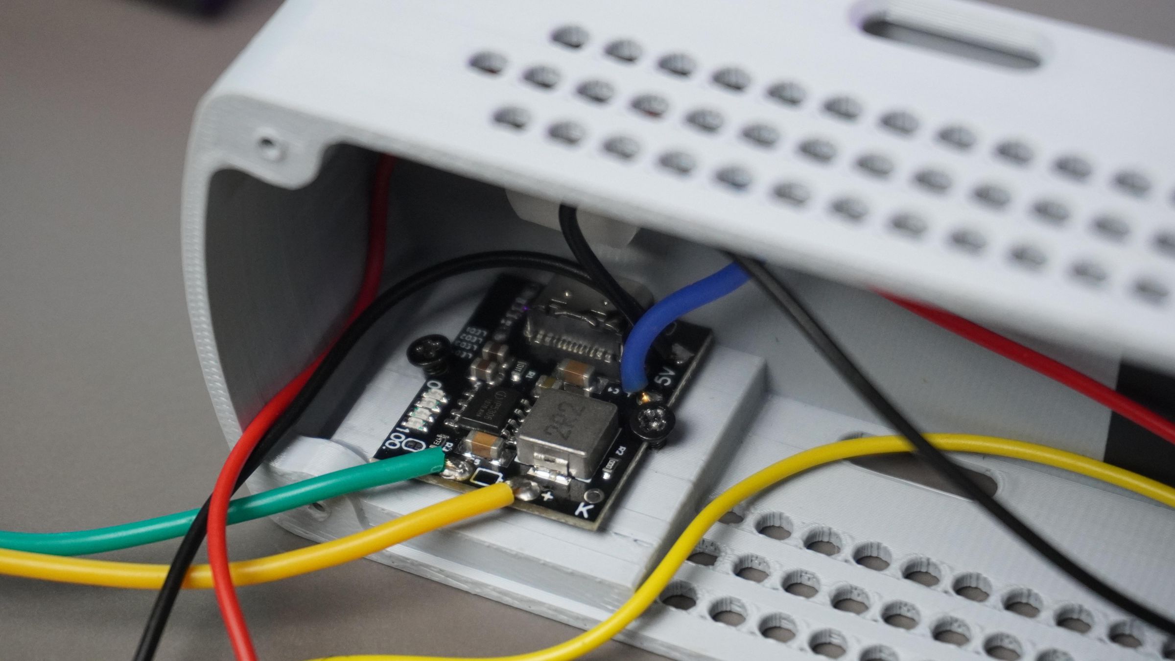
Step 7: Assembling the BMS and Switch
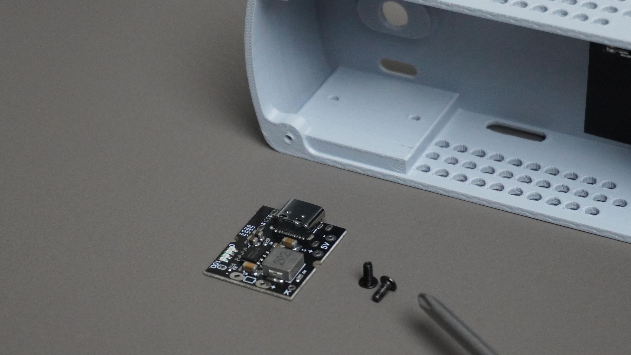 Take the BMS module and place it into the housing, aligning it with the mounting holes and the USB Type-C cutout. Secure it using two M2 screws.
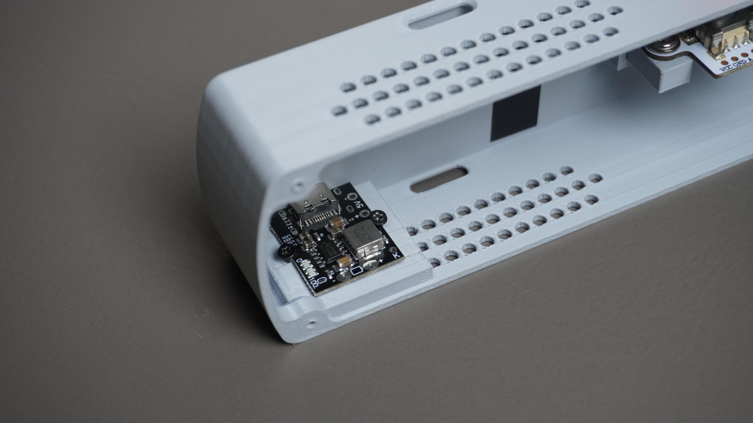
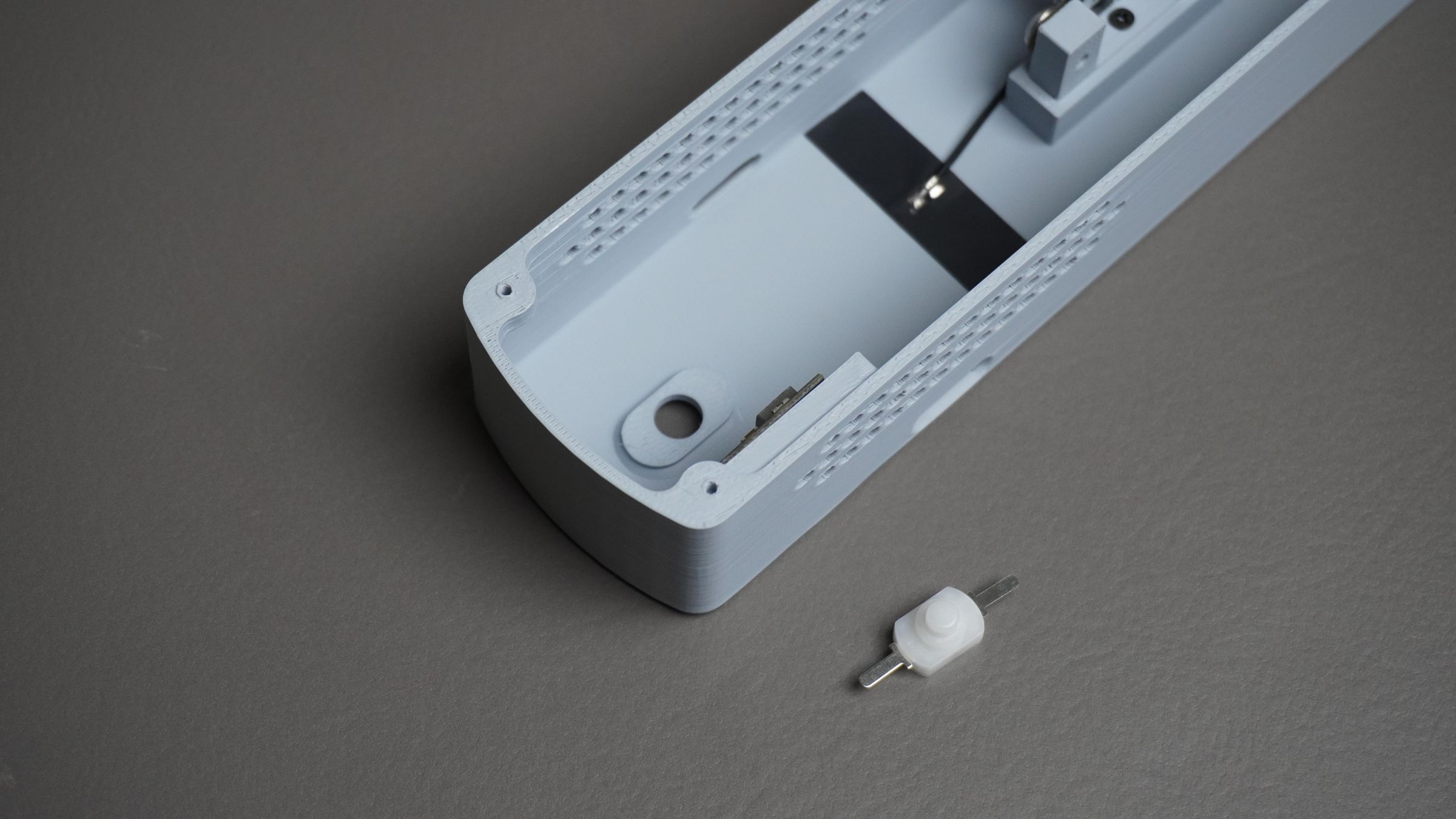
Next, insert the power switch into its dedicated slot in the housing. It should snap into place; however, if the fit is loose, apply a small amount of quick glue to hold it securely.
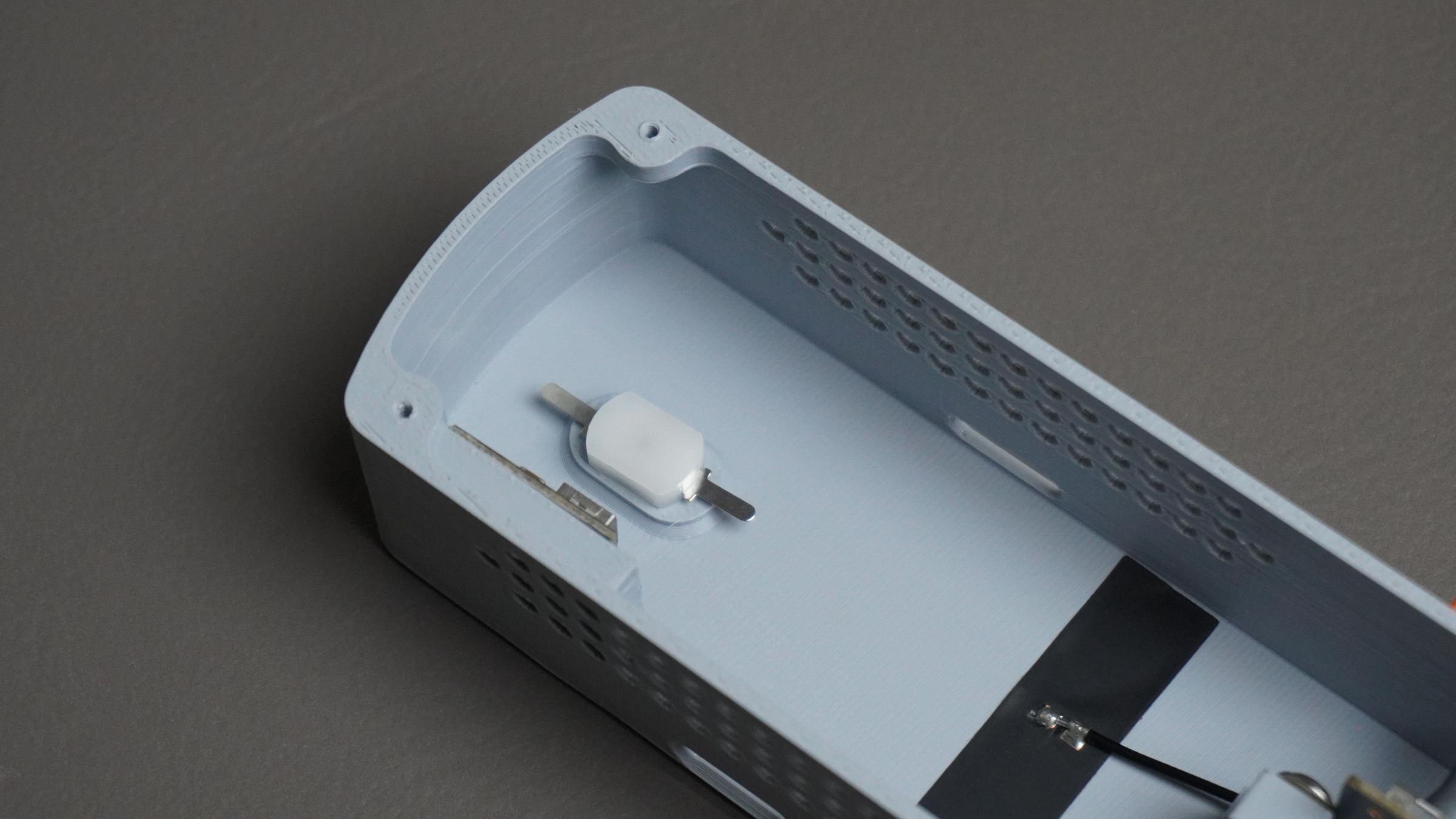
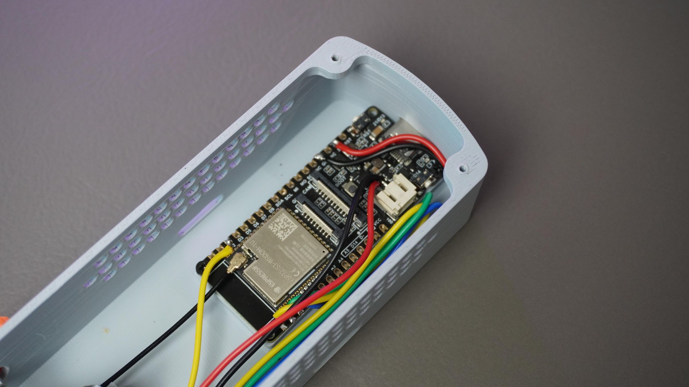
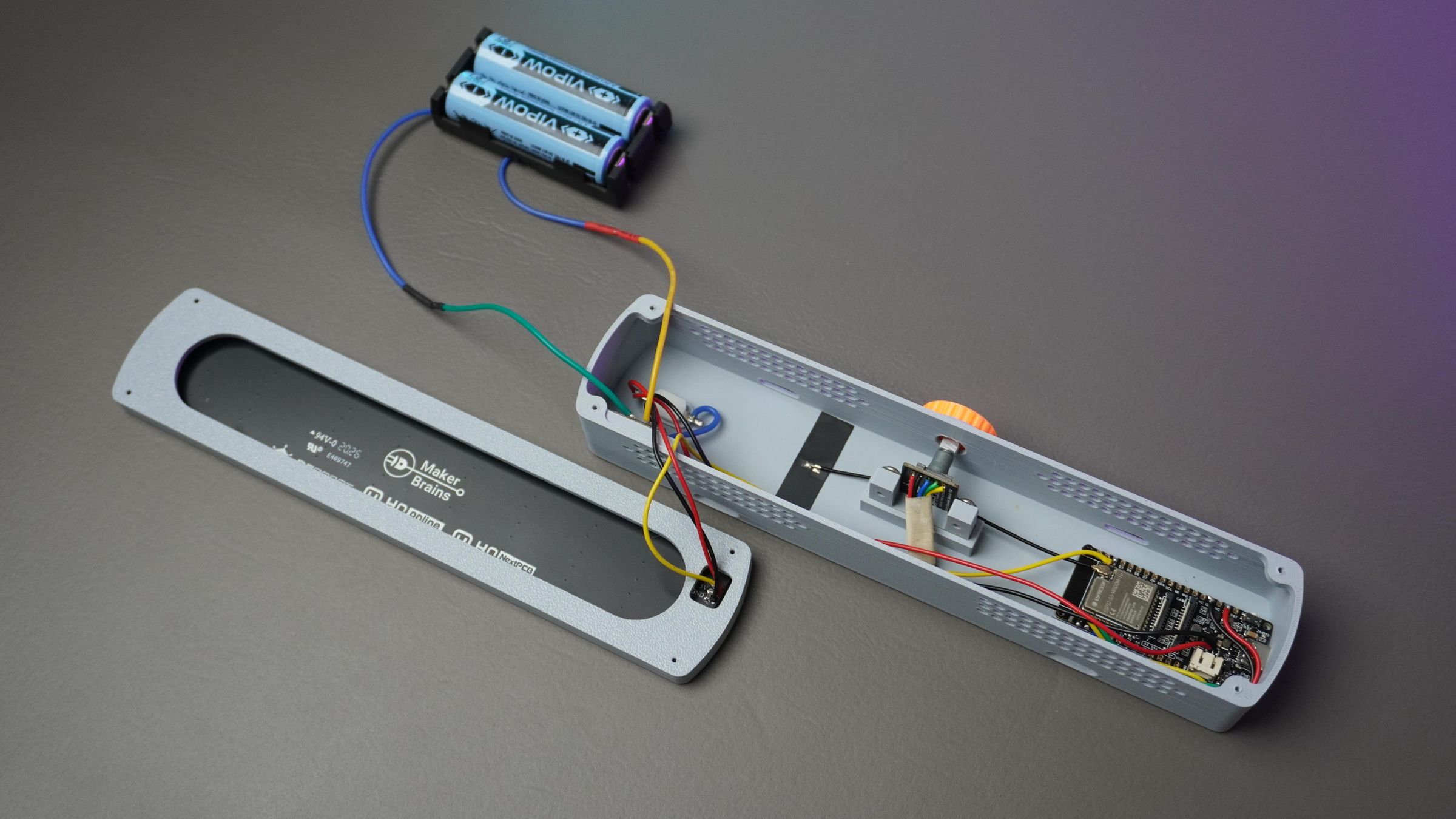
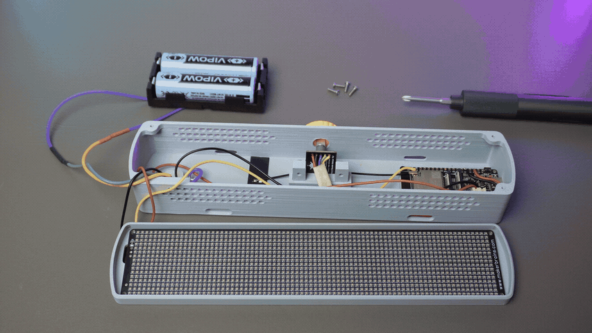
Step 8: Circuit Connections
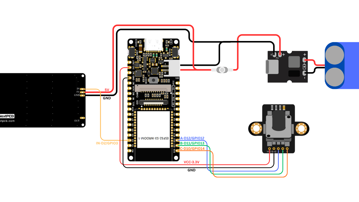
With all the components mounted, it's time to make the electrical connections.
Battery → BMS
Connect the battery pack to the BMS module:
- Battery Red (+) → +Ve
- Battery Black (-) → -Ve
Connect the output of the BMS as follows:
- BMS +5V Output → Switch
- Switch Output(+5V) → LED Matrix 5V (+Ve)
- BMS GND Output → LED Matrix GND (-Ve)
Power the ESP32 from the same supply:
- Switch Output(+5V) → ESP32 Battery IN +Ve
- BMS GND Output → ESP32 Battery IN -Ve
LED Matrix → ESP32
Connect the data input of the LED matrix to the ESP32:
- LED Matrix DIN → GPIO3 (D2)
Before soldering the LED matrix wires, make sure to pass them through the cable cutout in the Front Mount. This is easy to miss and will save you from desoldering the wires later.
Encoder → ESP32
- VCC ~ 3V3
- GND ~ GND
- A ~ GPIO12 (D12)
- B ~ GPIO13 (D11)
- C ~GPIO14 (D10)
Double-check all wiring before powering up the device. Reversing the battery polarity or LED matrix power connections can permanently damage the components.
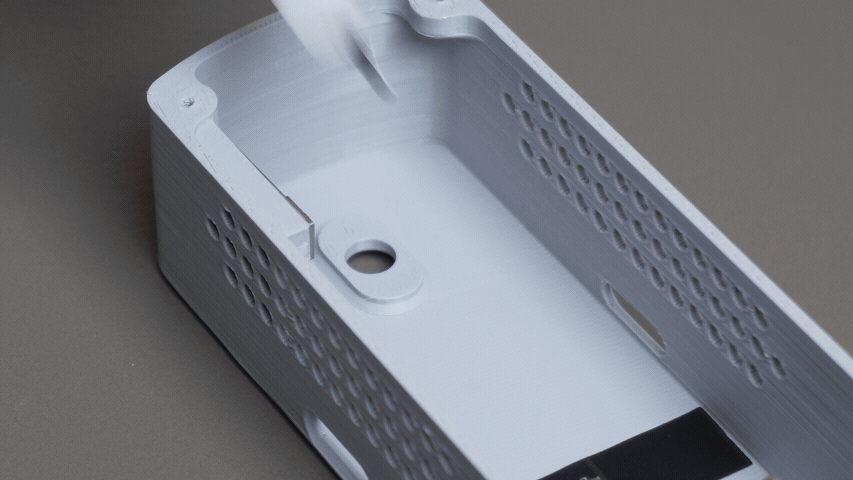
Step 9: Assembling the LED Matrix
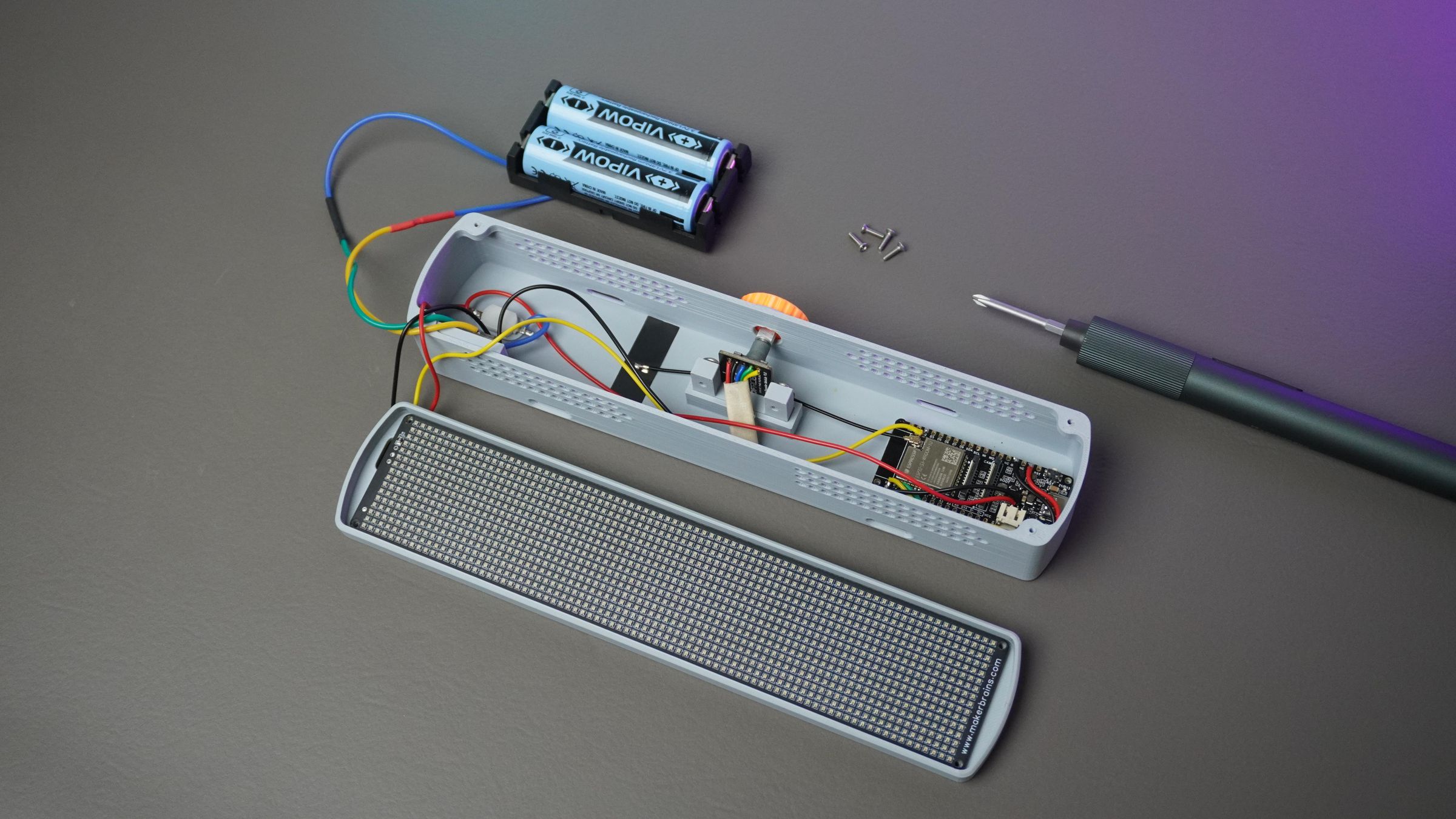
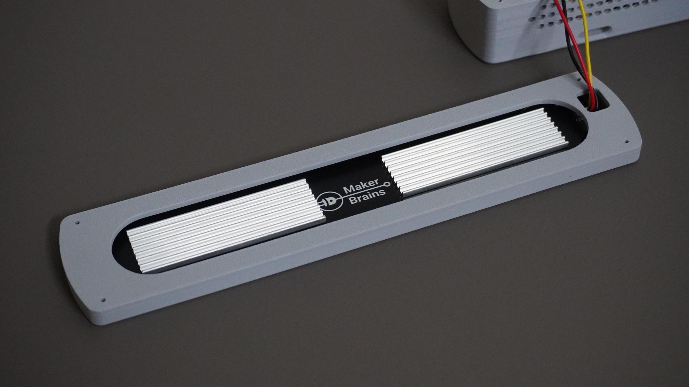
To help dissipate heat, stick the two heat sinks onto the back of the LED matrix PCB.
Next, place the Front Mount onto the housing and align the mounting holes.
Position the LED matrix on top of the Front Mount, again making sure all holes are aligned. Secure everything together using four M2 × 12 mm screws.
These screws hold the LED Matrix PCB, Front Mount, and Housing together, forming a sturdy assembly.
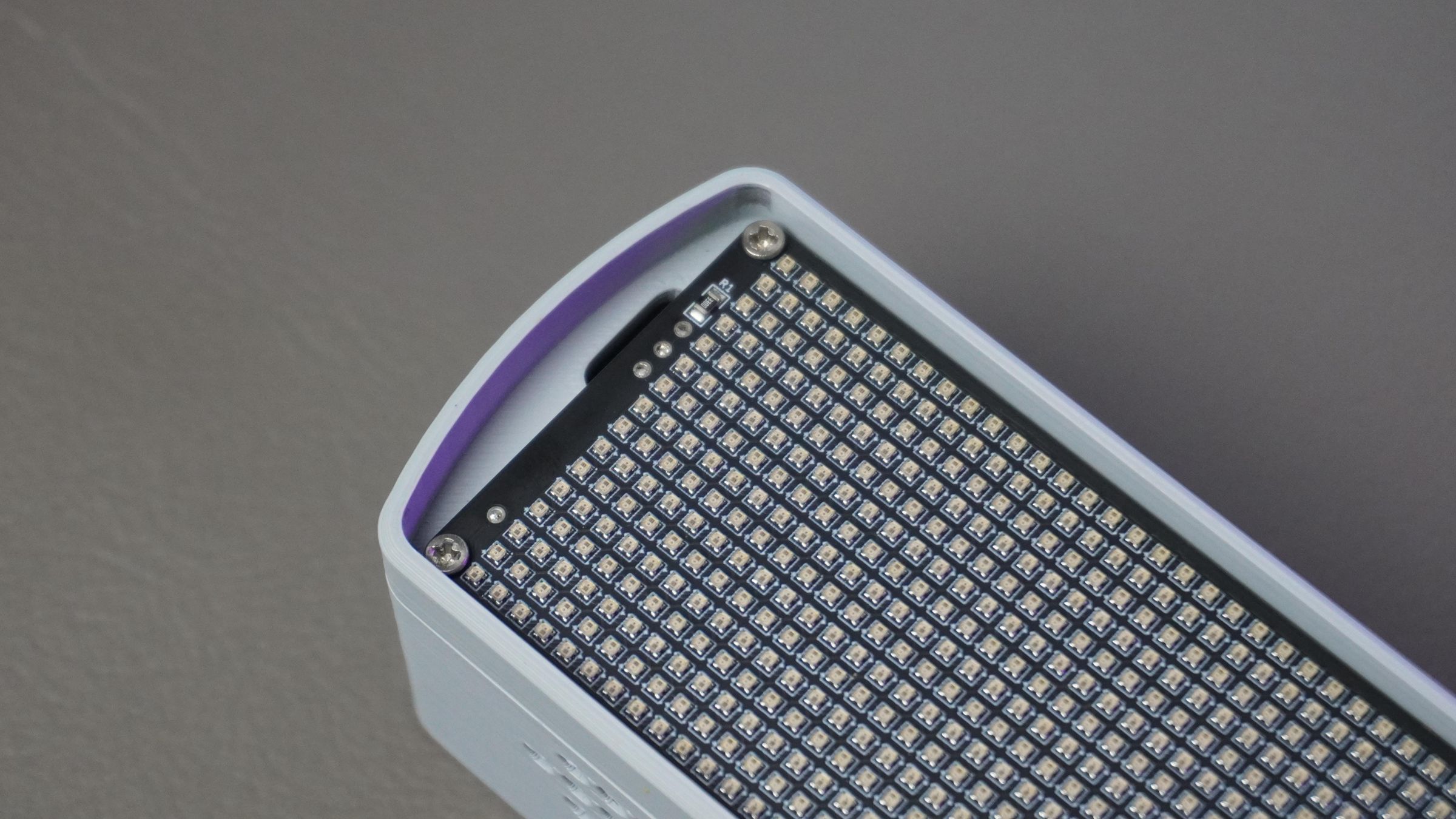
Step 10: Assembling the Matrix Grid
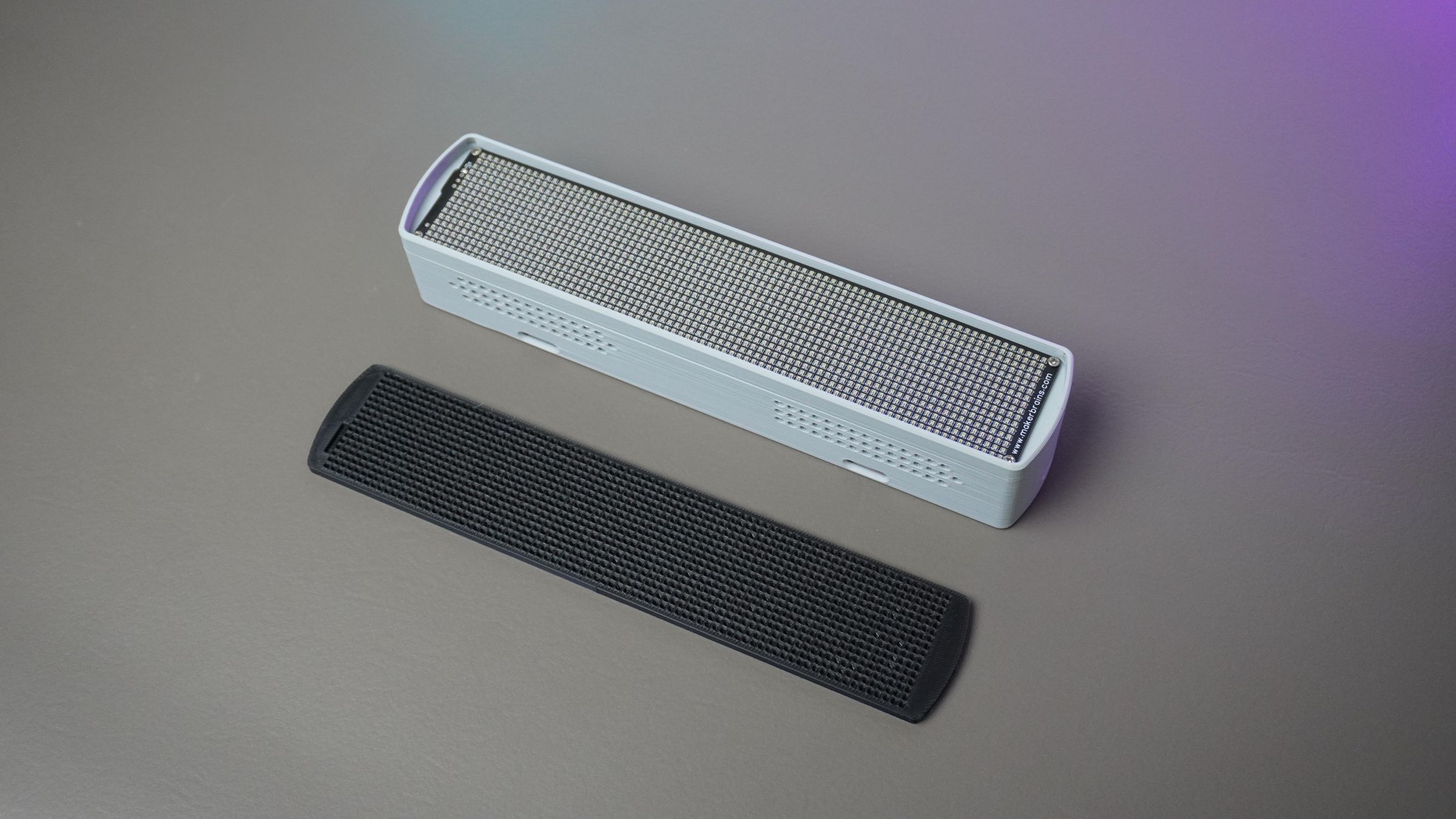
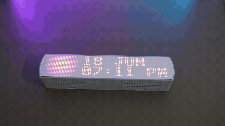
Take the 3D printed Grid and gently press it into the Front Mount. The grid sits directly on top of the LED matrix PCB, surrounding each LED to improve pixel separation and contrast.
The extended walls of the Front Mount hold the grid securely in place, so no glue or additional fasteners are required.
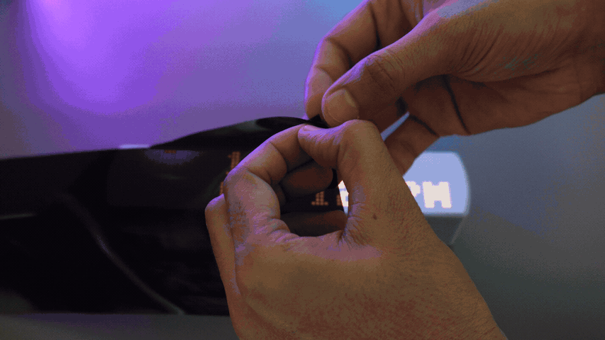
Step 11: Trying a Black Film
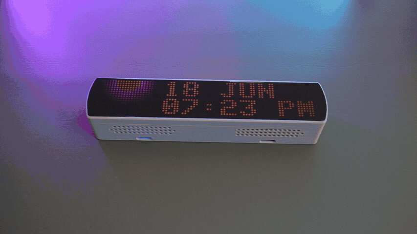
To give the Pixel Bar a cleaner and more premium look, I experimented with applying a black car window tint film over the grid diffuser.
I tested a few different tint shades and thicknesses before settling on one that provided a good balance between appearance and brightness.
To apply it, simply peel off the backing, stick the film onto the grid, and use an X-Acto knife to carefully trim the excess along the edges.
Keep in mind that the tint film blocks some of the light, so you may need to increase the LED brightness to around 30–40% (60–80 out of 255) for comfortable viewing. This increases power consumption and causes the PCB to warm up during extended use.
Without the tint film, the display looks great even at 10% brightness, consuming significantly less power and generating very little heat.
So the choice is yours:
- Black Tint Film → Sleek, premium "display panel" look, but higher brightness, power consumption, and heat.
- Plain White Grid → Better efficiency, lower temperatures, and excellent visibility at low brightness levels.
I personally liked the black film for its finished appearance, but the white diffuser is the more practical option for everyday use.
Step 12: Flashing the Initial Code
Before using Pixel Studio, you need to upload the base firmware to your ESP32. This firmware handles Wi-Fi connectivity, live casting, widgets, weather updates, YouTube statistics, and all communication with Pixel Studio.
Download the latest firmware from:
GitHub Repository: https://github.com/MukeshSankhla/Pixel-Bar
1. Install Arduino IDE
Download and install the latest version of the Arduino IDE: https://www.arduino.cc/en/software
2. Install the ESP32 Board Package
- Open Arduino IDE
- Navigate to:
File → Preferences
- In Additional Boards Manager URLs, add:
https://raw.githubusercontent.com/espressif/arduino-esp32/gh-pages/package_esp32_index.json- Click OK
- Open:
Tools → Board → Boards ManagerSearch for:
ESP32Install ESP32 by Espressif Systems.
3. Install Required Libraries
Open:
Sketch → Include Library → Manage LibrariesInstall the following libraries:
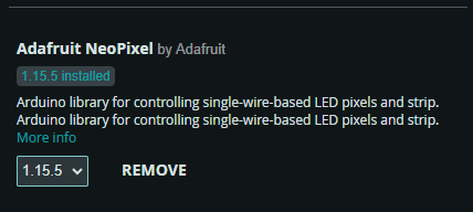
- Adafruit NeoPixel
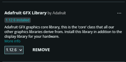
- Adafruit GFX Library
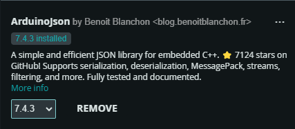
- ArduinoJson
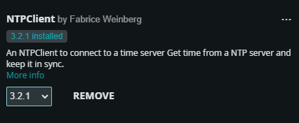
- NTPClient
The following libraries are included with the ESP32 Board Package:
- WiFi
- HTTPClient
- WiFiClientSecure
- WiFiUDP
4. Configure Wi-Fi
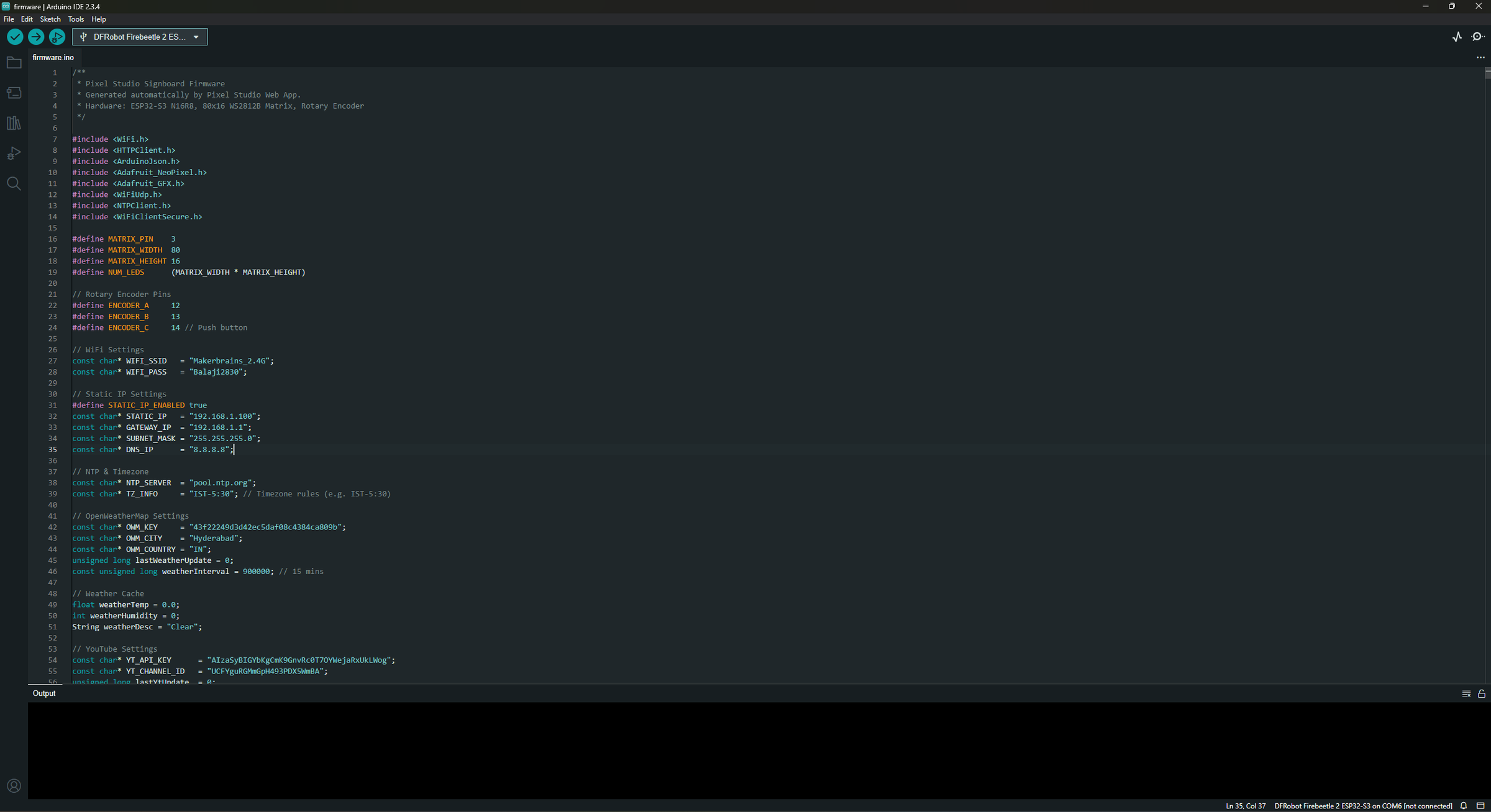
Open the firmware and edit the following lines:
const char* WIFI_SSID = "Your WiFi Name";
const char* WIFI_PASS = "Your WiFi Password";
Replace them with your home Wi-Fi credentials.
Note: The Pixel Bar and Pixel Studio must be connected to the same local network for Live Cast to work.
5. Configure Time Zone
The built-in clock synchronizes automatically using an NTP server.
const char* NTP_SERVER = "pool.ntp.org";
const char* TZ_INFO = "IST-5:30";
Replace the timezone string with the appropriate value for your region.
Examples:
RegionTime Zone
- India - IST-5:30
- London - GMT0BST
- New York - EST5EDT
- Tokyo - JST-9 .......
6. Weather Configuration
The Weather Widget uses the OpenWeatherMap API.
Create an API Key
- Create a free account at OpenWeatherMap.
- Generate an API Key.
- Copy the generated key.
Update the firmware:
const char* OWM_KEY = "YOUR_API_KEY";Then select your location:
const char* OWM_CITY = "Hyderabad";
const char* OWM_COUNTRY = "IN";
Replace these with your own city and country code.
Examples:
- OWM_CITY = "London";
- OWM_COUNTRY = "GB";
- OWM_CITY = "New York";
- OWM_COUNTRY = "US";
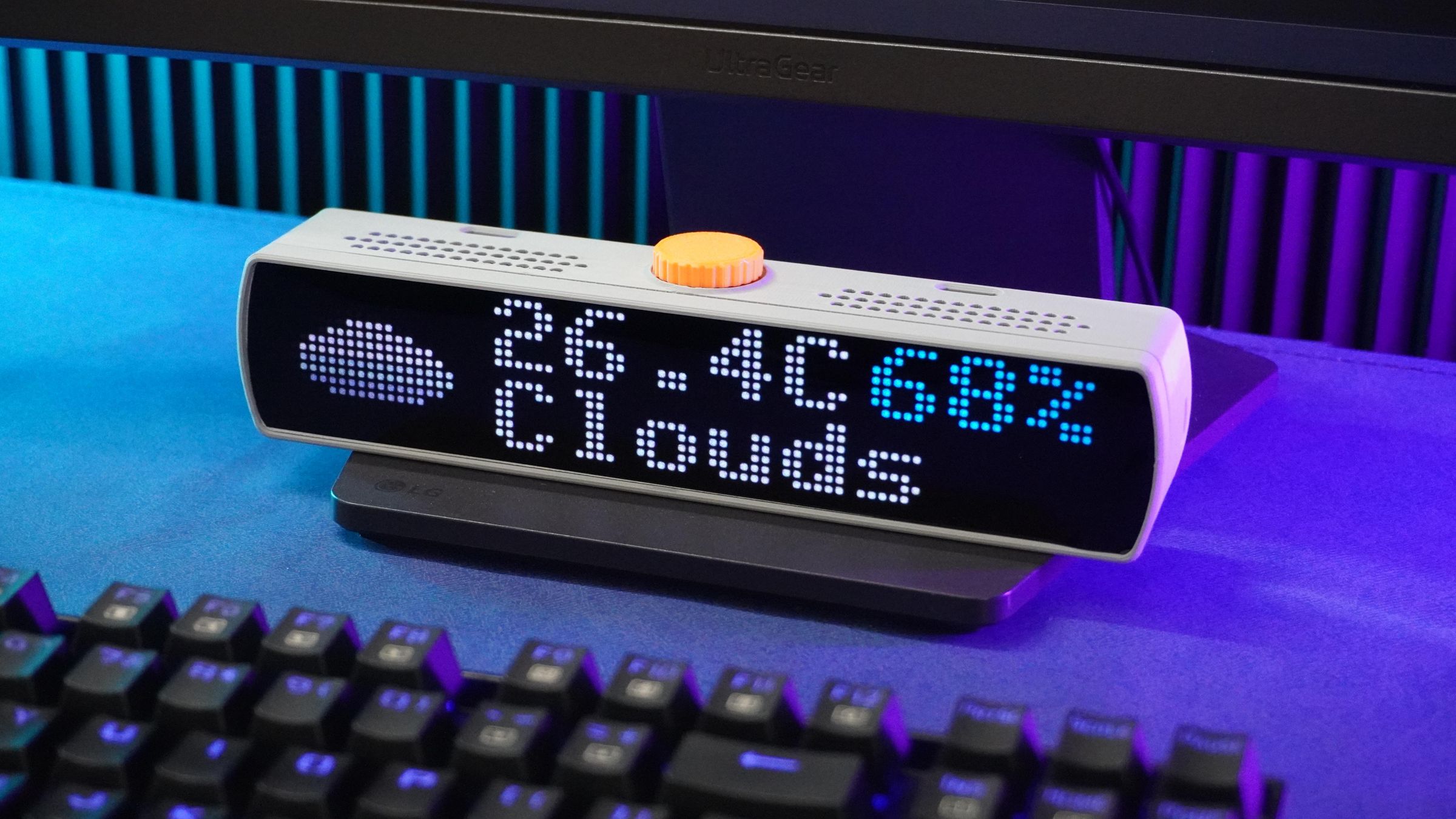
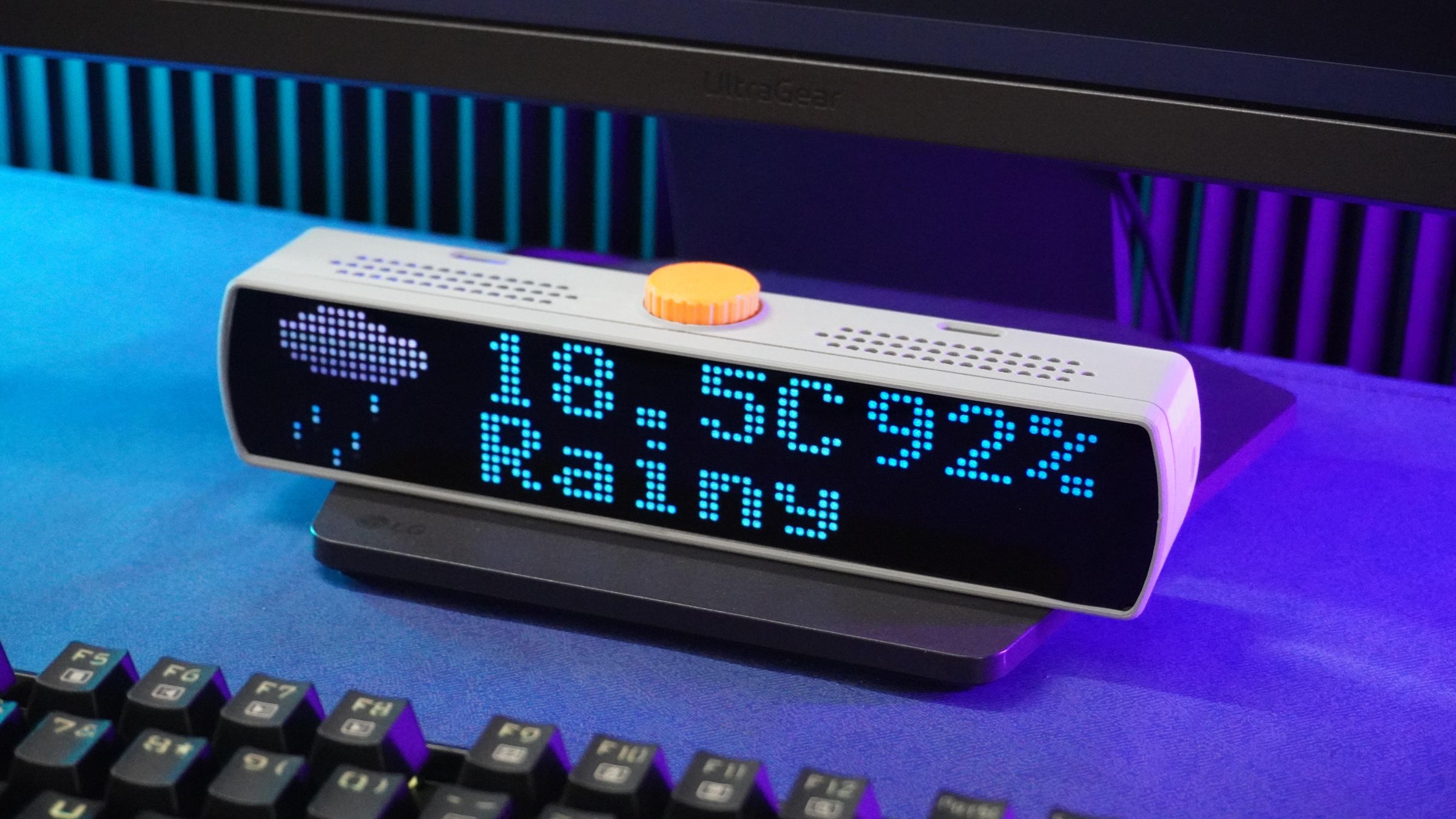
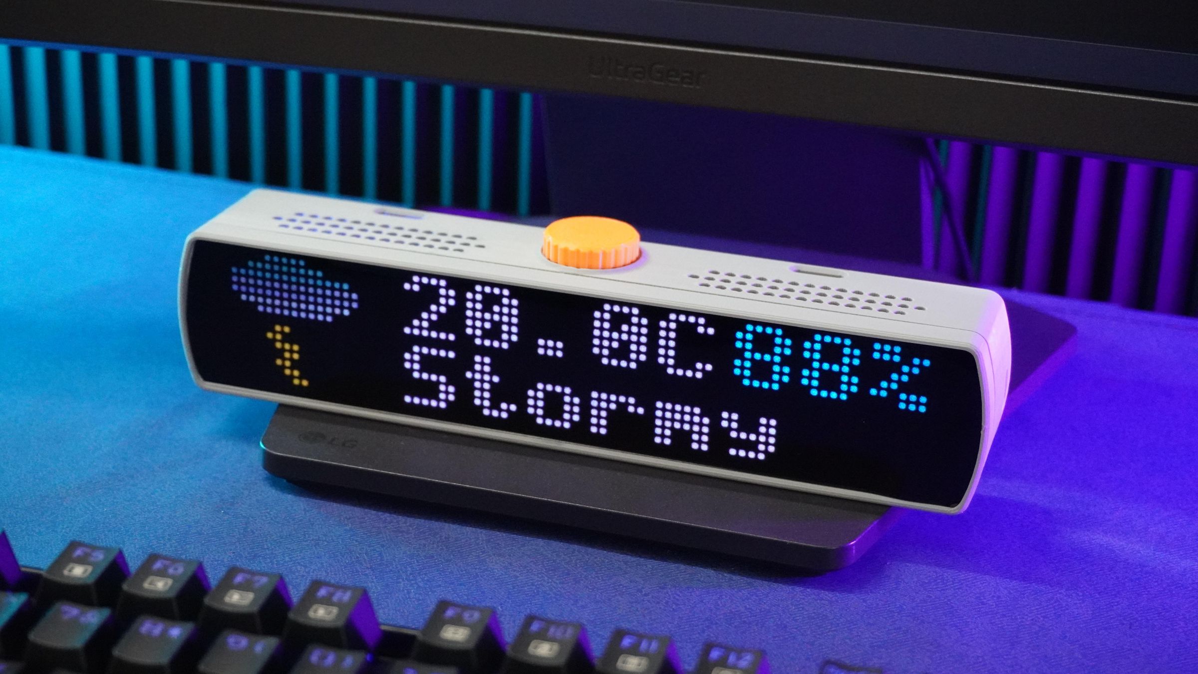
The weather information is refreshed every 15 minutes.
7. Select Your Board
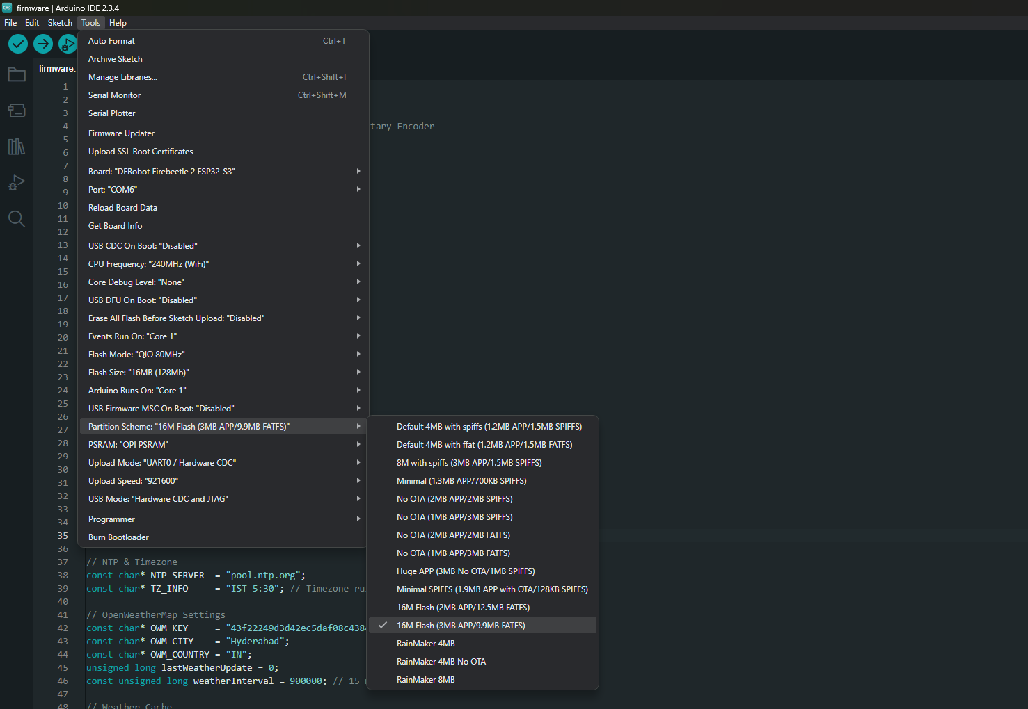
- Connect the ESP32 using a USB cable.
Go to:
Tools → BoardSelect:
DFRobot Firebeetle 2 ESP32-S3Then configure the following settings:
Setting Value:
- Board Type - DFRobot Firebeetle 2 ESP32-S3
- Port - Select your ESP32 COM Port
- Flash Size - 16MB
- Partition Scheme - Huge APP
- PSRAM - OPI PSRAM
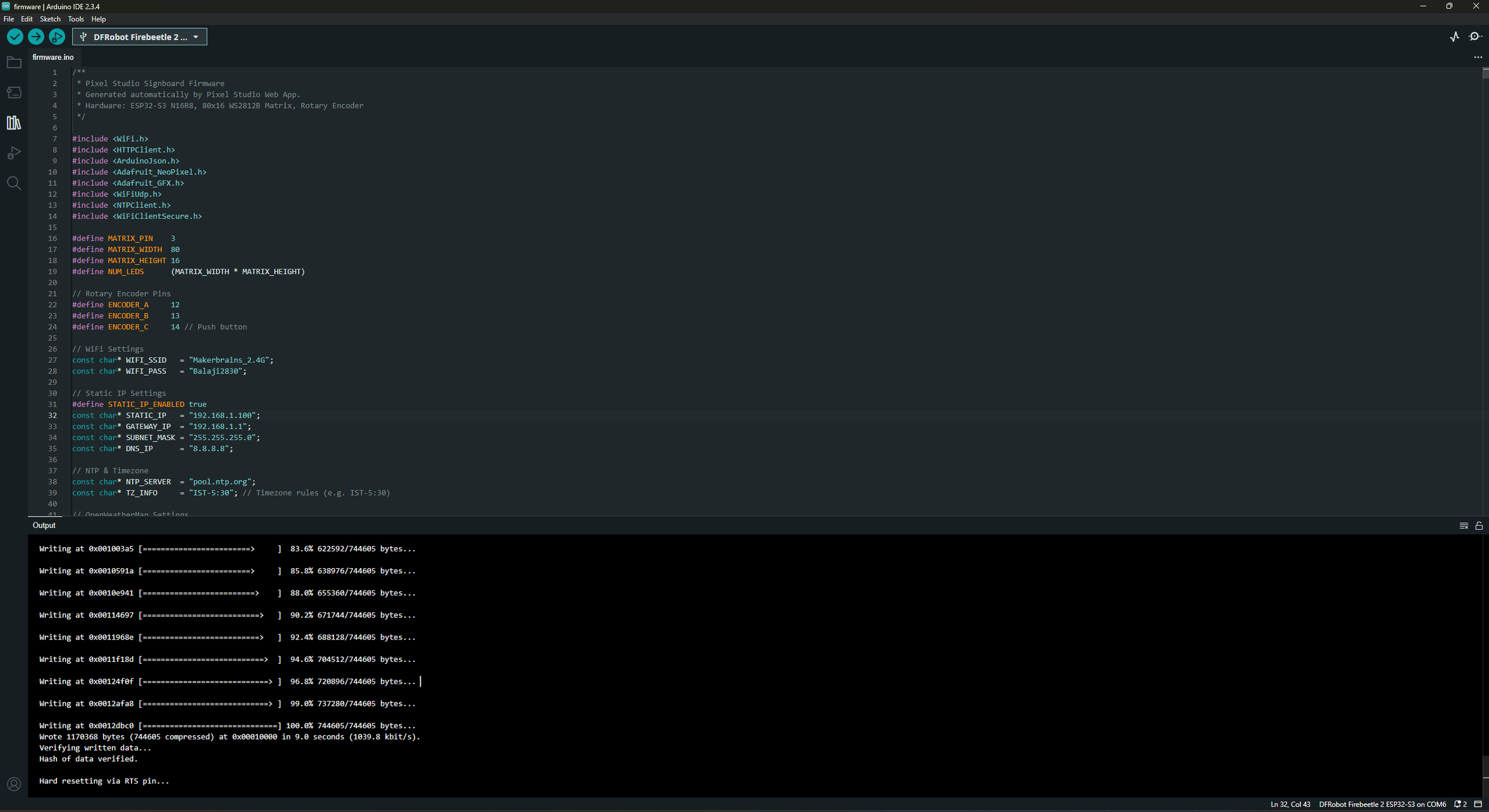
Click Upload.
The firmware will compile and upload to the ESP32.
Note:
The configuration shown in this guide is intended only for the initial firmware setup using the Arduino IDE. Since you downloaded the base firmware from the GitHub repository, you'll need to manually edit values such as your Wi-Fi credentials, static IP address, time zone, weather settings, and YouTube API information directly in the source code before uploading it to the ESP32.
Once you start using Pixel Studio, this manual editing is no longer necessary. Pixel Studio provides a user-friendly interface to configure these settings, and they are automatically embedded into the generated firmware during export.
You can configure everything directly within the app:
- ⚙️ Settings (Top Toolbar) – Configure your Wi-Fi SSID, password, and static IP/network settings.
- 🕒 Clock Widget – Set the time zone, NTP server, and clock preferences.
- 🌤️ Weather Widget – Enter your OpenWeatherMap API key, city, and country code.
- 📺 YouTube Widget – Add your Google API Key and YouTube Channel ID.
- 🎨 Scene & Display Settings – All widgets, layouts, animations, stickers, backgrounds, brightness, and display preferences are saved automatically.
When you click Export Firmware, Pixel Studio generates a complete Arduino project with all of your configured values already filled in. You simply need to open the generated project, compile it, and upload it to your ESP32—no manual code editing required. This makes updating your Pixel Bar much faster and eliminates the risk of configuration errors.
Step 13: Pixel Studio
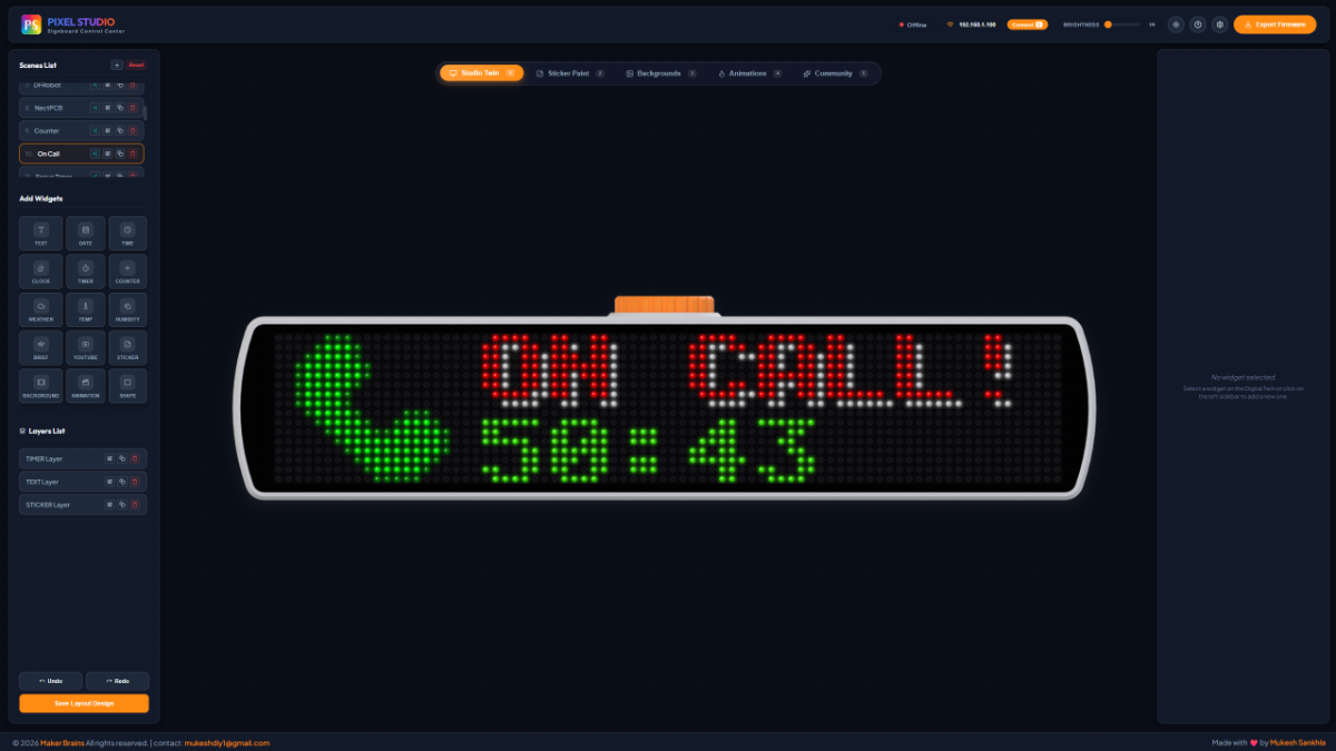
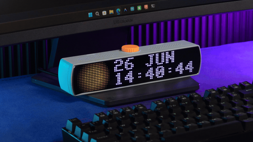
Pixel Studio is the companion application for the Pixel Bar, making it easy to create, customize, and display dynamic content on your LED display. Whether you want a digital clock, weather information, animated artwork, or scrolling text, Pixel Studio provides an intuitive interface to design and manage everything.
Widgets:
Add useful widgets to your Pixel Bar, including:
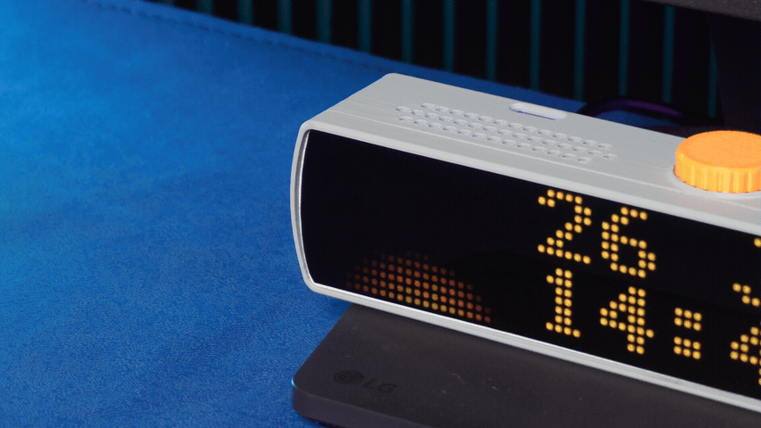
- Digital & Analog Clock
- Weather
- Calendar
- Scoreboard
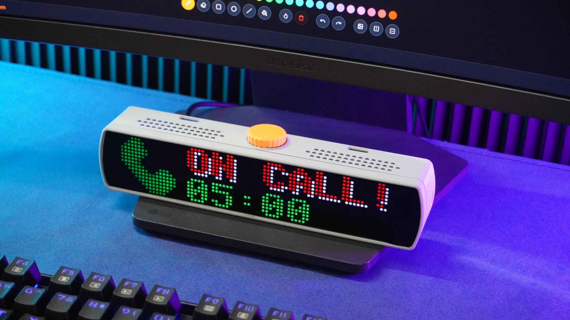
- Text Messages
- Countdown Timer
- And many more...
Arrange and customize widgets to create your own personalized dashboard.
Scene Builder:
Scene Builder allows you to combine multiple widgets, animations, text, and images into a single scene. Create different scenes for your home, office, gaming setup, or events, then switch between them whenever you like.
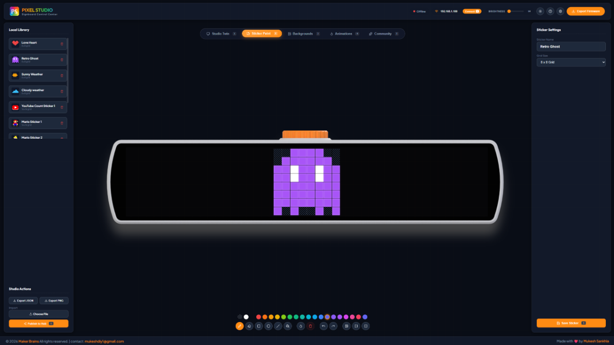
Sticker Builder:
The Sticker Builder is a built-in pixel art editor that lets you create your own icons and graphics directly inside Pixel Studio. Design anything from weather icons and gaming characters to logos, emojis, and custom symbols.
Features include:
- Draw pixel-perfect artwork on multiple grid sizes.
- Color picker with a wide range of colors.
- Fill, erase, mirror, and drawing tools.
- Save stickers locally for reuse in future projects.
- Export and import sticker packs as JSON files.
- Publish your creations to the Community Hub so others can download and use them.
Simply drag your saved stickers into any scene to instantly enhance your display.
Background Builder:
Create custom pixel backgrounds using gradients, patterns, solid colors, or your own artwork. Backgrounds can be used independently or combined with widgets and animations.
Animation Builder:
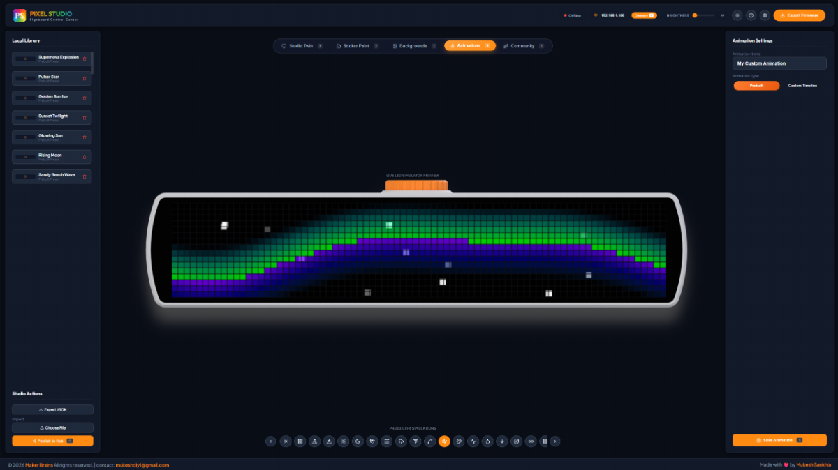
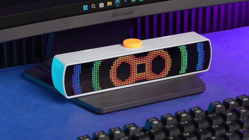
Bring your Pixel Bar to life with animated content.
- Pre-built Animations – Choose from a growing library of ready-to-use animations.
- Custom Timeline Editor – Create frame-by-frame animations with complete control over timing, transitions, and playback.
Community Hub:
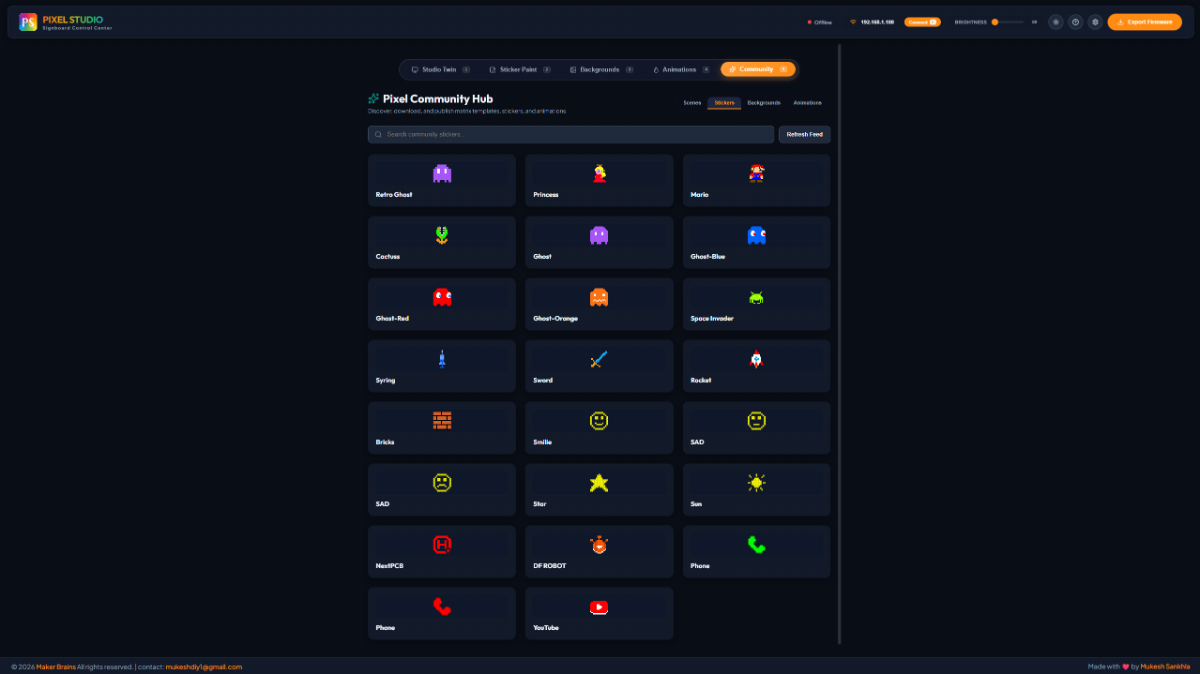
The Community Hub is an online library where Pixel Studio users can share their creations.
Browse thousands of community-made:
- Scenes
- Stickers
- Backgrounds
- Animations
With a single click, you can download and use community content, or upload your own creations for others to enjoy.
Export Firmware:
Once you've finished designing your scenes, simply click Export Firmware.
Pixel Studio automatically packages:
- Your scene layouts
- Widgets
- Stickers
- Backgrounds
- Animations
- Display settings
into a firmware file that can be flashed to your ESP32 using the Arduino IDE or your preferred flashing tool.
Live Cast:
Live Cast lets you stream content directly from Pixel Studio to your Pixel Bar in real time. This is ideal for testing new designs, previewing animations, or displaying live information without rebuilding or reflashing the firmware.
How to Connect
- Upload the Arduino firmware to the ESP32.
- On startup, the ESP32 connects to your configured home Wi-Fi network.
- Note the device's static IP address (for example, 192.168.1.100).
- Make sure your computer and the Pixel Bar are connected to the same Wi-Fi network.
- In Pixel Studio, enter the ESP32's IP address in the Connect box at the top of the application.
- Click Connect.
Once connected, any changes you make in Pixel Studio—including widgets, stickers, backgrounds, and animations—are streamed instantly to the Pixel Bar, allowing you to preview your designs in real time without reflashing the device.
Step 14: Configure the YouTube Subscriber Counter
The Pixel Bar can display your YouTube subscriber count, total videos, total views, and other channel statistics using the YouTube Data API v3. To enable this feature, you'll need a Google Cloud API key and your YouTube Channel ID.
9.1 Create a Google Cloud Project
- Open the Google Cloud Console:
- https://console.cloud.google.com/
- Sign in with your Google account.
- Click the Project dropdown at the top of the page.
- Click New Project.
- Enter a project name (for example, Pixel Bar) and click Create.
9.2 Enable the YouTube Data API v3
- Open the API Library:
- https://console.cloud.google.com/apis/library
- Search for:
- YouTube Data API v3
- Open the API page.
- Click Enable.
Once enabled, your project can access public YouTube channel statistics.
9.3 Generate an API Key
- Open the Credentials page:
- https://console.cloud.google.com/apis/credentials
- Click + CREATE CREDENTIALS.
- Select API Key.
- Google will generate a new API key.
It will look similar to:
AIzaSyAxxxxxxxxxxxxxxxxxxxxxxxxxxxxxxxxCopy this key.
9.4 Find Your YouTube Channel ID
There are several ways to find your Channel ID.
Open:
https://www.youtube.com/account_advanced
Your Channel ID will be displayed on this page.
Example:
UC-lHJZR3Gqxm24_Vd_AJ5YwNote: The YouTube Data API v3 provides a free daily quota that is more than sufficient for the Pixel Bar's default update interval of one request per hour. If you reduce the refresh interval significantly or use the same API key for multiple projects, you may consume your daily quota more quickly.
Conclusion:
Congratulations! You've reached the end of the Pixel Bar project.
Building Pixel Bar is more than just assembling an LED display—it's an opportunity to explore electronics, embedded programming, networking, real-time graphics, and interactive software in a single project. Along the way, you've learned how the hardware and software work together to create a fully customizable smart pixel display.
The real fun begins after the build. Experiment with different layouts, design your own stickers, create unique animations, build personalized dashboards, or develop scenes for your desk, gaming setup, workshop, or events. Every project can look completely different, and that's what makes Pixel Bar so enjoyable to use.
Even if you don't have the hardware yet, you can still dive into Pixel Studio. The built-in digital preview lets you create scenes, draw pixel art, design animations, and visualize your ideas directly in your browser. It's a great way to learn pixel design, prototype new concepts, and prepare content before ever flashing a device.
Don't forget to share your creativity with the community. Publish your scenes, stickers, backgrounds, and animations to the Community Hub, and explore what other makers have created. Your designs might inspire someone else's next project, just as their creations may inspire yours.
If you build a Pixel Bar, I'd love to see it. Share your photos, videos, modifications, and custom designs on social media, GitHub, or in the Pixel Studio Community. Whether you've built the project exactly as shown or added your own improvements, every build contributes to making the ecosystem even better.
Thank you for following along, and happy building! 🚀