 A month ago, I found myself holding a GNSS module and wondering:
"Can I build a navigation device where I simply enter destination coordinates, and the device continuously shows the distance and direction to the target while I'm walking?"
That simple question became the starting point of this project.
I quickly assembled a rough prototype using an ESP32-C6, a GNSS receiver, and a small display. After writing some test code, I was surprised to see the system successfully calculating the distance to the destination in real time as I moved.
However, there was one major limitation.
GNSS modules can determine movement direction only when the user is actively moving. If you stop walking, the heading information becomes unreliable because the receiver no longer has enough movement data to calculate the travel direction.
While researching solutions, I discovered that dedicated waypoint navigation devices had been used long before smartphone navigation became common. These devices combined position data with a compass to continuously indicate the direction of a destination.
That inspired me to add a digital compass to the project.
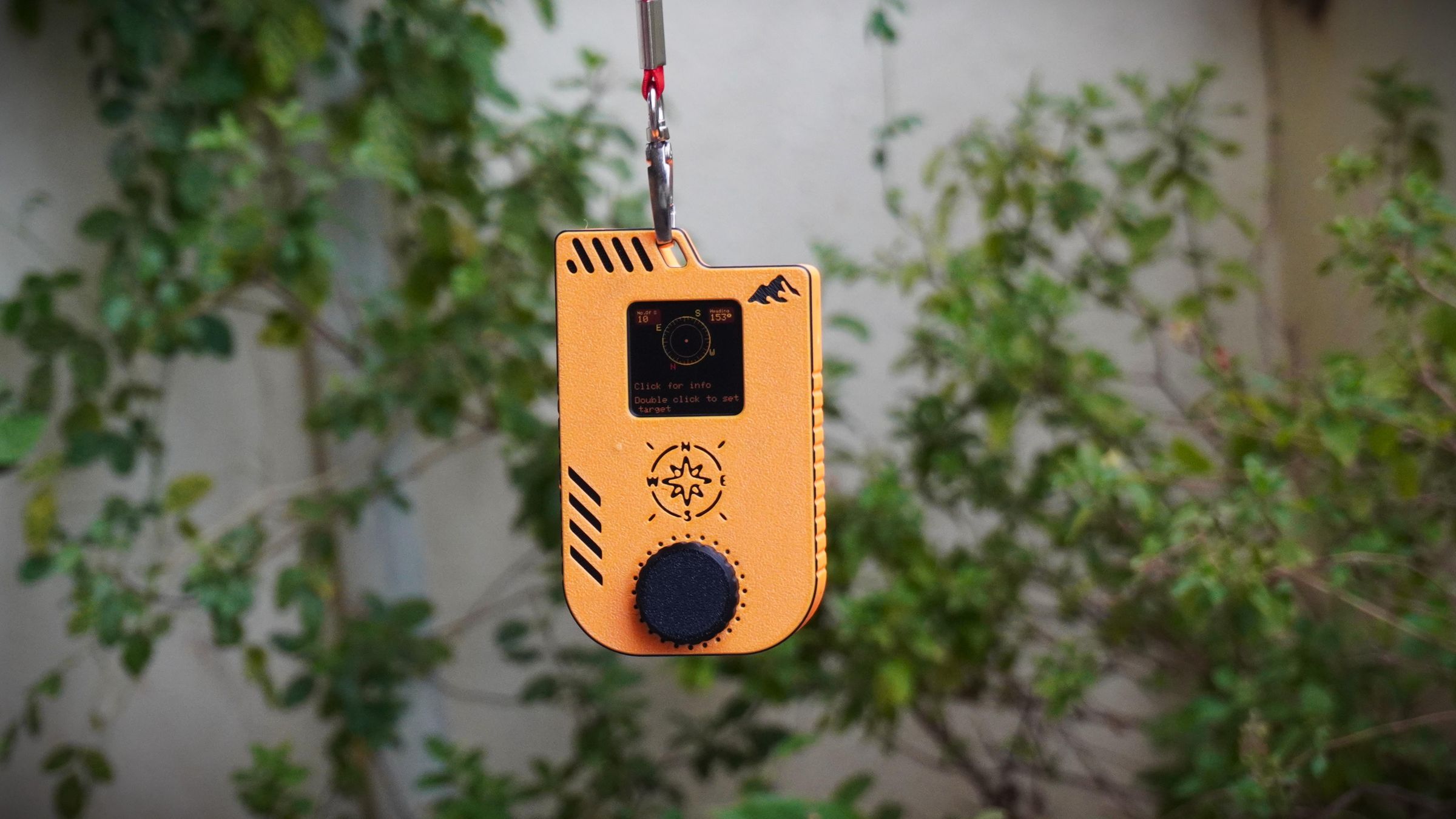
By integrating a BMM350 magnetometer, the navigator could now determine its orientation even while standing still. The result was exactly what I had imagined: a compact handheld device capable of displaying both the distance and bearing to a predefined waypoint in real time.
Even more impressive, the system consistently achieved an accuracy of approximately ±5 meters, which is excellent for a DIY navigation project.
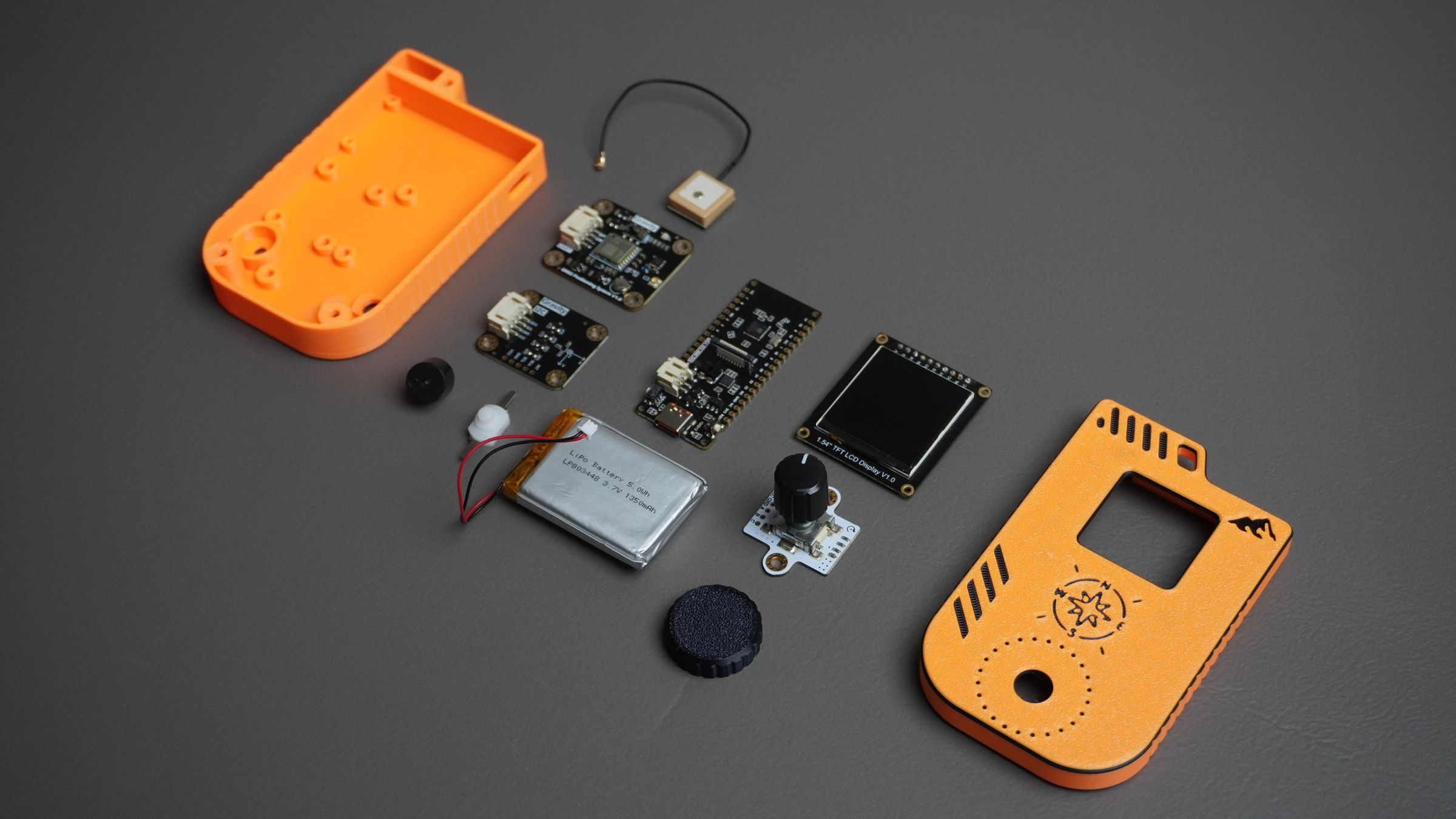
The hardware used in this build includes:
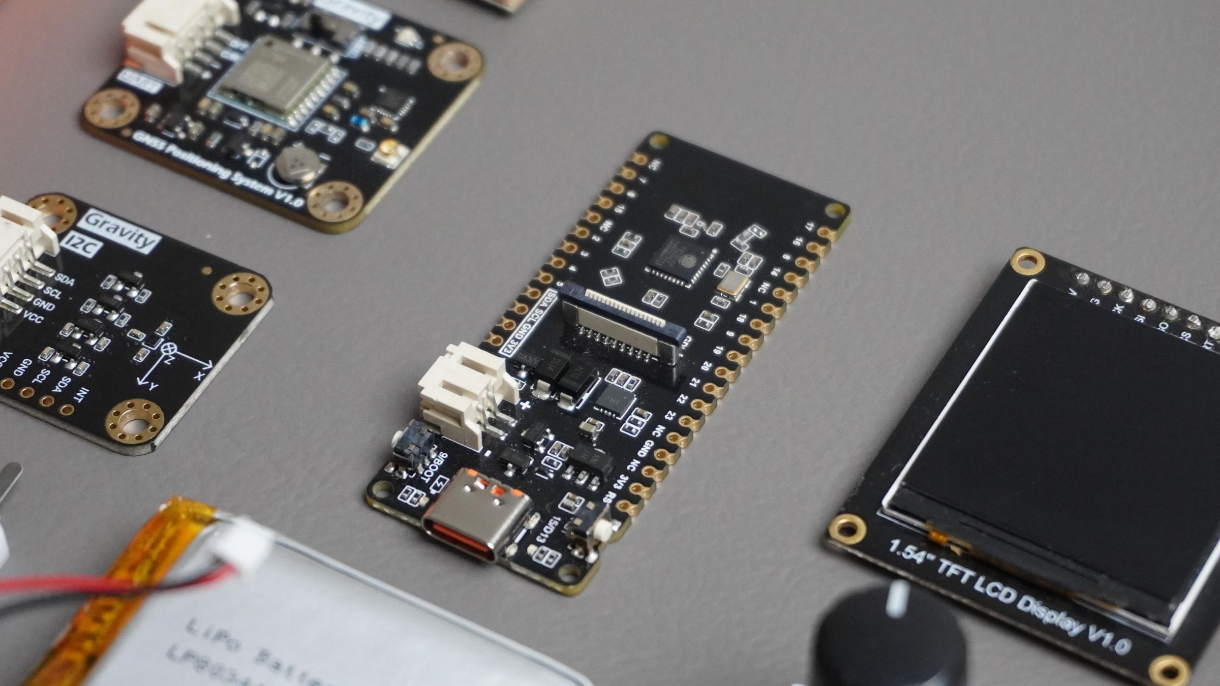
- DFRobot FireBeetle 2 ESP32-C6
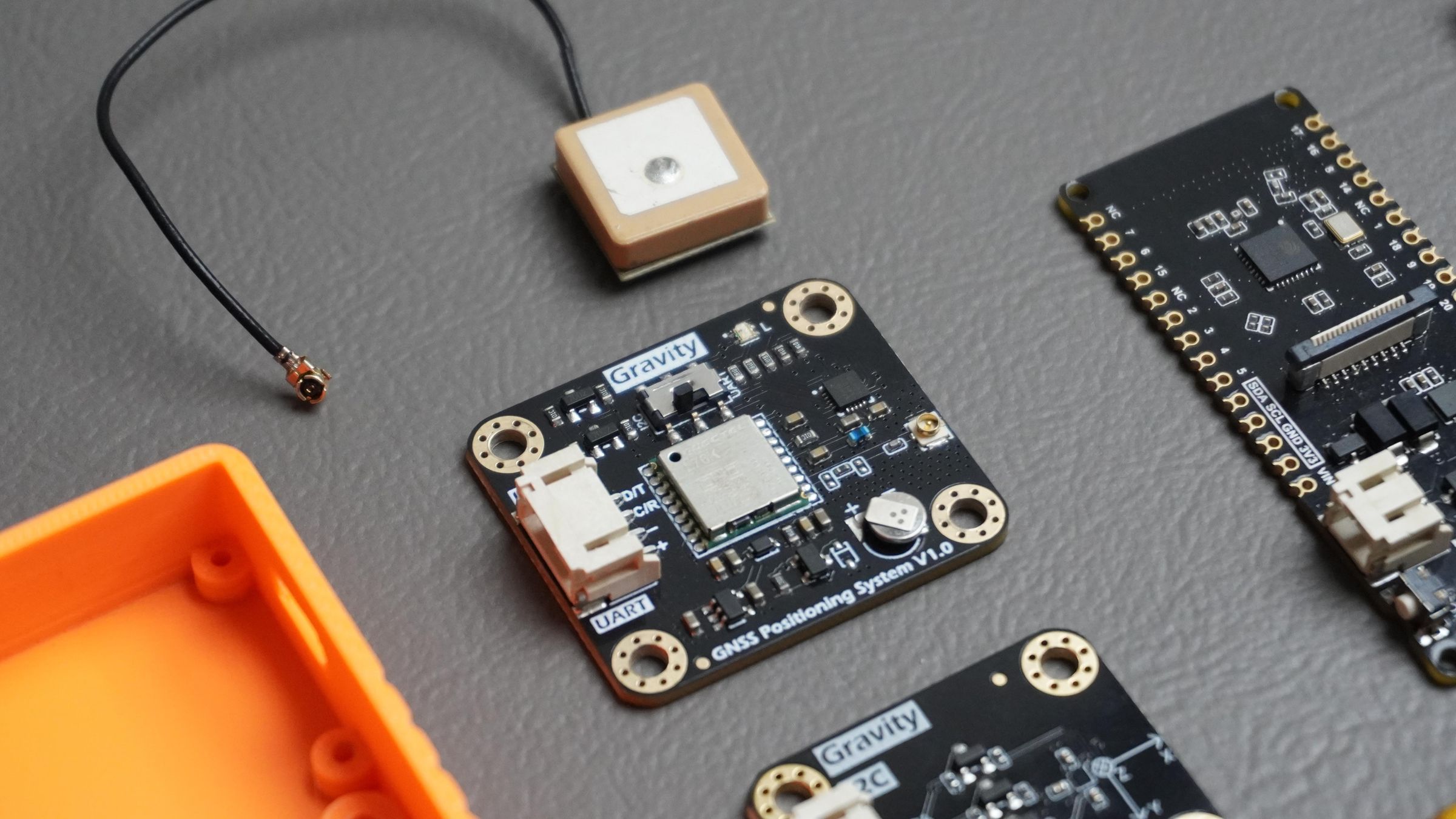
- Gravity GNSS Positioning Module
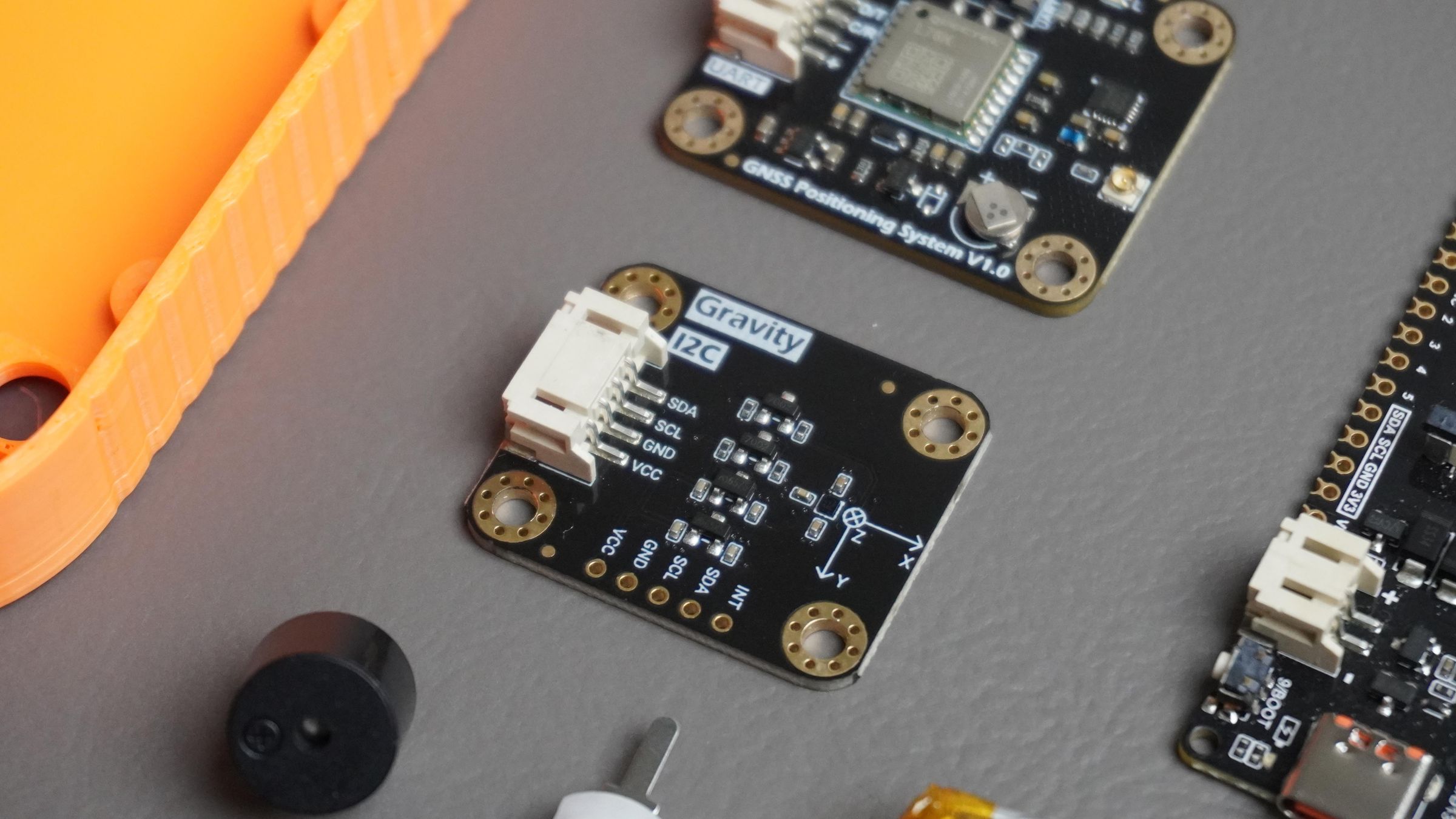
- Gravity BMM350 Triple-Axis Magnetometer
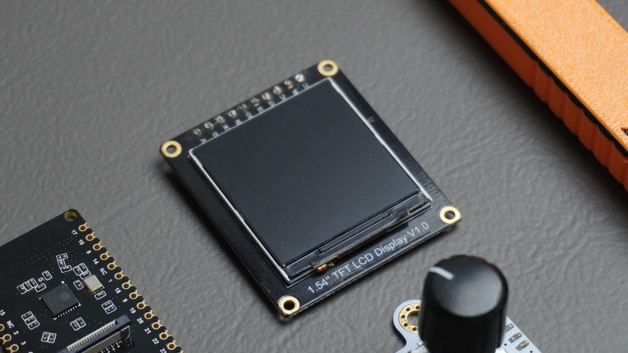
- Fermion 1.54" 240×240 IPS TFT Display
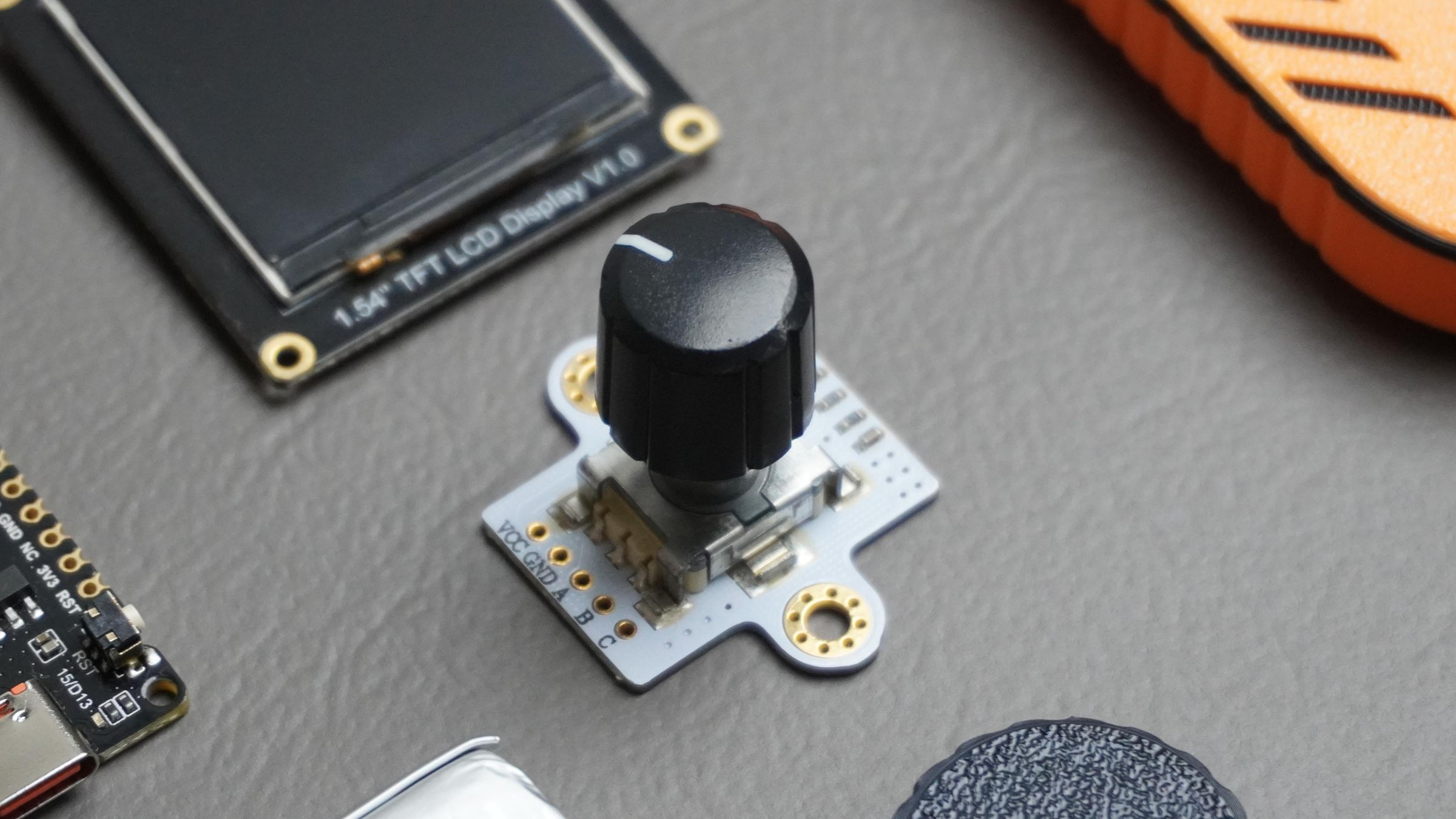
- Rotary Encoder for user input
- Piezo Buzzer for feedback
- LiPo Battery for portable operation
To complete the project, everything was packaged inside a compact custom enclosure designed in Fusion 360, transforming the prototype into a practical handheld navigation device.
In this tutorial, I'll show you how I designed, assembled, programmed, and tested this DIY Waypoint Navigator (Pathfinder) so you can build one yourself.
Supplies
Electronics
- 1× DFRobot FireBeetle 2 ESP32-C6
- 1× Gravity GNSS Positioning Module
- 1× Gravity BMM350 Triple-Axis Magnetometer
- 1× Fermion 1.54" 240×240 IPS TFT Display
- 1× Rotary Encoder
- 1× Piezo Buzzer
- 1× Li-Po battery
- 1× Mini power switch
Hardware
- M2 Screw Kit
- M3 Screw Kit
- Screwdriver
Fabrication
- Access to a 3D Printer or
- Pre-printed enclosure parts
Software
- Arduino IDE
- Autodesk Fusion 360 (for enclosure design and modification)
Step 1: What Is GNSS, How Does It Work?
Before building the Pathfinder, it's helpful to understand the technology that makes it possible.
What Is GNSS?
GNSS stands for Global Navigation Satellite System. It is the general term used for satellite-based positioning systems that allow receivers on Earth to determine their location.
Several GNSS constellations are currently operating around the world:
- GPS (United States)
- GLONASS (Russia)
- Galileo (European Union)
- BeiDou (China)
Modern GNSS receivers can communicate with multiple satellite systems simultaneously, improving accuracy and reducing the time required to obtain a position fix.
How Does GNSS Work?
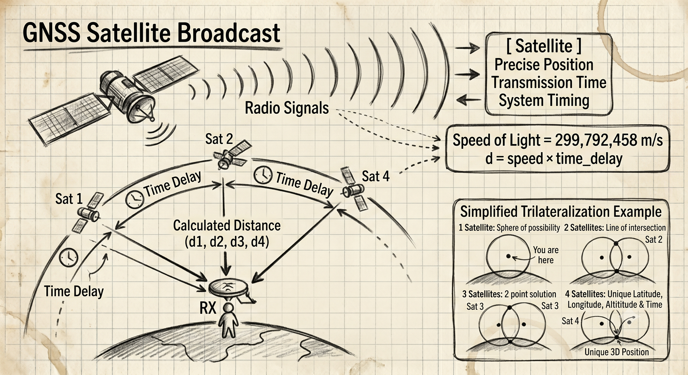
Each GNSS satellite continuously broadcasts signals containing:
- Its precise position in space
- The exact transmission time
- System timing information
The GNSS receiver measures how long these signals take to reach it from multiple satellites.
Since radio signals travel at the speed of light, the receiver can calculate its distance from each satellite.
By combining measurements from at least four satellites, the receiver performs a process called trilateration to determine:
- Latitude
- Longitude
- Altitude
- Time
The more satellites visible to the receiver, the better the positioning accuracy tends to be.
Simplified Example
Imagine standing somewhere on Earth:
- One satellite tells you that you are somewhere on a large sphere.
- A second satellite narrows the possible location.
- A third satellite reduces the possibilities even further.
- A fourth satellite provides enough information to calculate an accurate 3D position.
This process happens continuously, often multiple times per second.
GNSS in This Project
The Pathfinder uses a DFRobot Gravity GNSS Positioning Module connected to the ESP32-C6.
The GNSS module continuously provides:
- Current latitude
- Current longitude
- Altitude
- Ground speed
- Number of satellites in view
Once a destination waypoint is entered, the ESP32 compares the current GNSS coordinates with the destination coordinates and calculates:
Step 2: Distance to Destination: the Haversine Formula
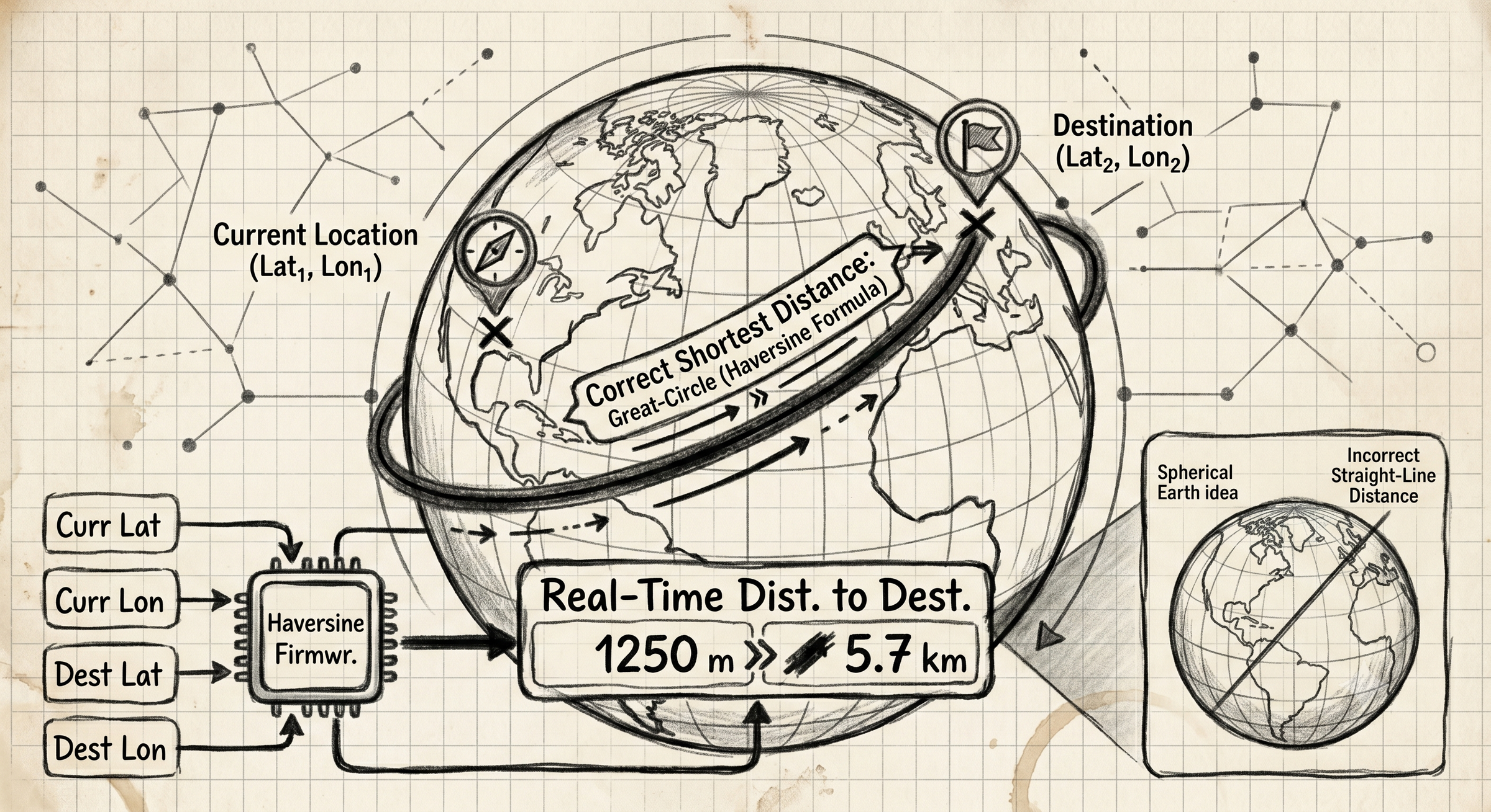
Once the navigator knows your current coordinates and the destination coordinates, it needs to calculate the distance between those two points.
At first glance, this sounds simple. However, the Earth is not flat, it's approximately spherical. Because of this, a straight-line calculation using latitude and longitude would produce inaccurate results over longer distances.
To solve this problem, the firmware uses the Haversine Formula, a well-known navigation equation that calculates the shortest distance between two points on the surface of a sphere.
The formula takes four inputs:
- Current Latitude
- Current Longitude
- Destination Latitude
- Destination Longitude
Using these coordinates, it calculates the great-circle distance, which is the shortest path between two points along the Earth's surface.
This distance is continuously updated as the user moves, allowing the navigator to display the remaining distance to the selected waypoint in real time.
In the firmware, the calculated distance is displayed in:
- Meters for nearby destinations
- Kilometers for longer distances
This provides a simple and intuitive way to track progress toward the target.
Step 3: Bearing to Destination
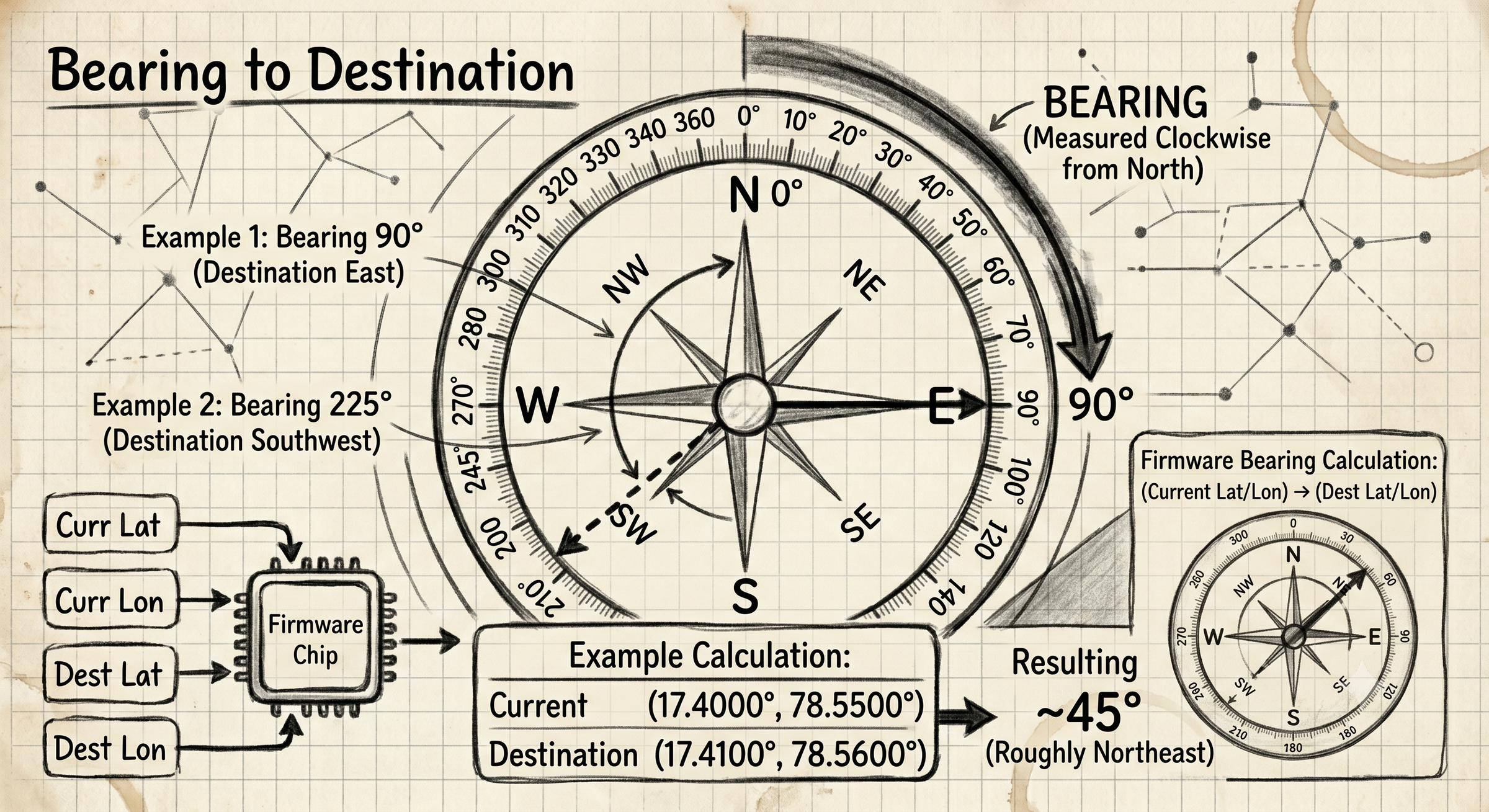
Knowing the distance alone isn't enough, you also need to know which direction to travel.
This is where the bearing calculation comes in.
A bearing is the compass direction from one location to another, measured clockwise from geographic north.
For example:
- 0° = North
- 90° = East
- 180° = South
- 270° = West
If the navigator calculates a bearing of 90°, the destination is directly east of your current position.
If it calculates a bearing of 225°, the destination lies to the southwest.
The firmware calculates this bearing using the current GNSS coordinates and the destination coordinates.
Example
Imagine you are standing at:
- Latitude: 17.4000°
- Longitude: 78.5500°
And your destination is:
- Latitude: 17.4100°
- Longitude: 78.5600°
The bearing calculation determines the direction from your current location to the waypoint. In this example, the destination would be roughly northeast of your position.
Step 4: Combining Bearing With the Digital Compass
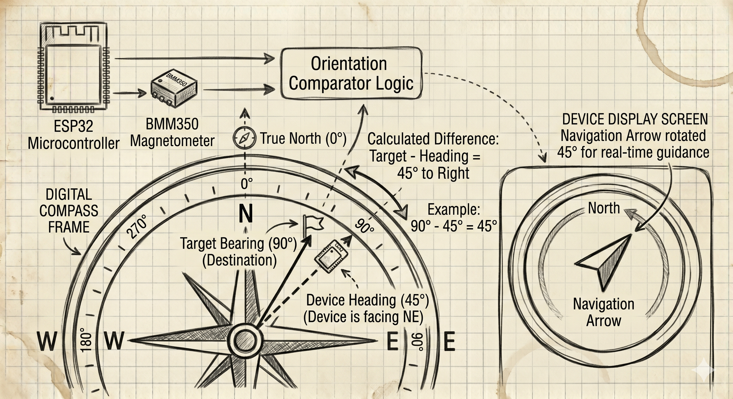
The calculated bearing tells us where the destination is relative to true north, but it does not tell us which way the device is currently facing.
That's where the BMM350 magnetometer comes in.
The magnetometer continuously measures the device's heading, allowing the ESP32 to determine its current orientation.
The firmware then compares:
Target Bearing
−
Current Heading
to determine where the destination lies relative to the device.
For example:
- Target Bearing = 90° (East)
- Device Heading = 45° (North-East)
The destination is 45° to the right of the direction you are currently facing.
The navigation arrow on the display is rotated by this difference, providing real-time guidance toward the selected waypoint.
This combination of GNSS positioning, bearing calculation, and digital compass heading is what allows the Pathfinder to continuously point toward the destination, even when the user is standing still.
Step 5: Why I Chose the FireBeetle 2 ESP32-C6
At the heart of this project is the DFRobot FireBeetle 2 ESP32-C6, which turned out to be an excellent fit for a portable navigation device.
I chose it for three main reasons:
- Affordable – At around $5.90 USD, it offers excellent value for the features provided.
- Battery Friendly – It includes a built-in LiPo battery connector and charging circuit, eliminating the need for a separate charging module.
- Powerful Enough – The ESP32-C6 easily handles GNSS data processing, compass calculations, display updates, and user input without being excessive for the task.
Another major advantage is its built-in Wi-Fi and Bluetooth connectivity. Instead of entering coordinates directly on the device(Hard Code), I can create a simple web interface that allows waypoint latitude and longitude values to be sent wirelessly over a local network.
This significantly improves the user experience while keeping the hardware simple and compact.
Overall, the FireBeetle 2 ESP32-C6 provided the perfect balance of cost, features, performance, and power management for this Pathfinder.
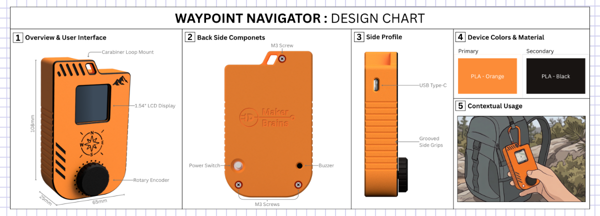
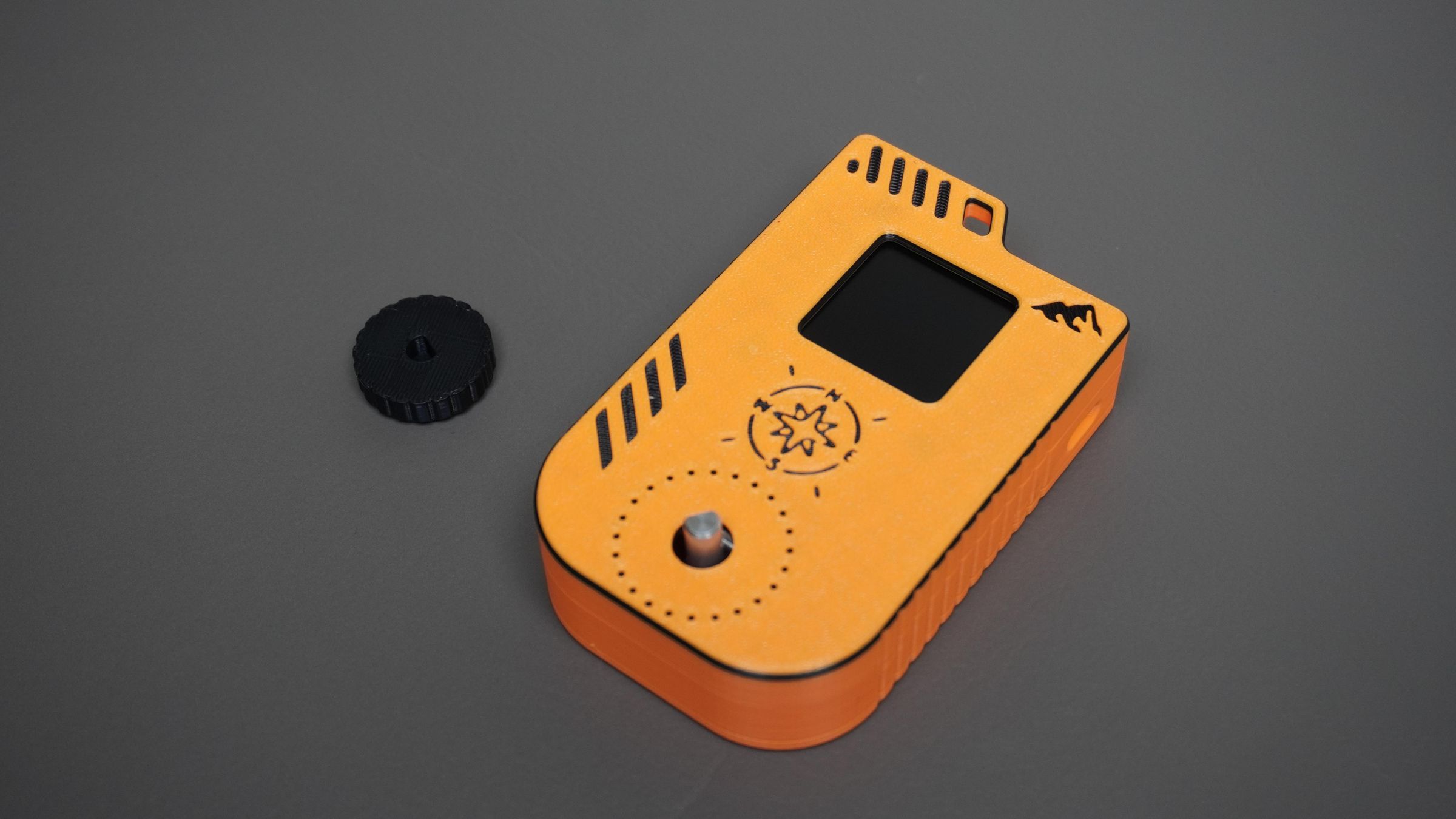
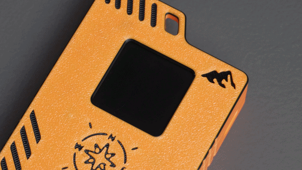
Step 6: Designing the Enclosure in Fusion 360
I designed a custom enclosure in Fusion 360 to transform the prototype into a compact handheld device.
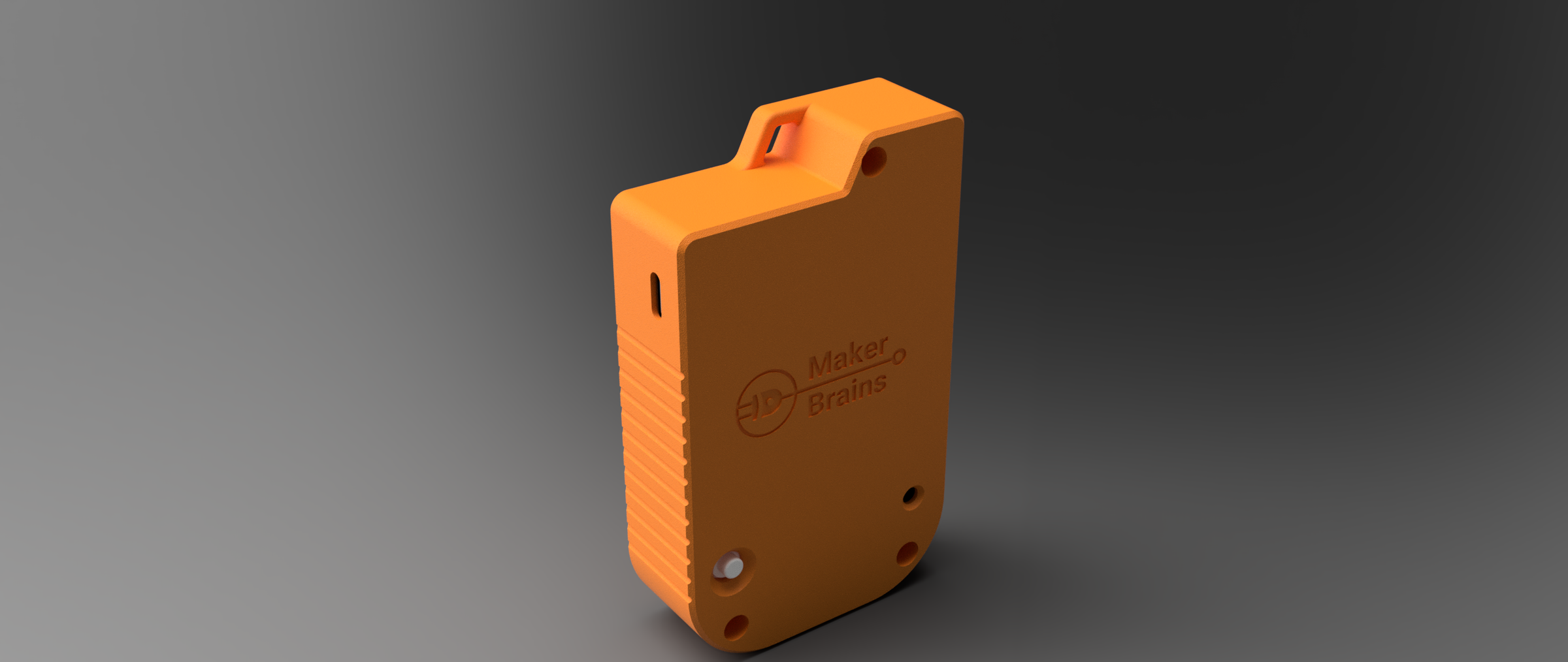
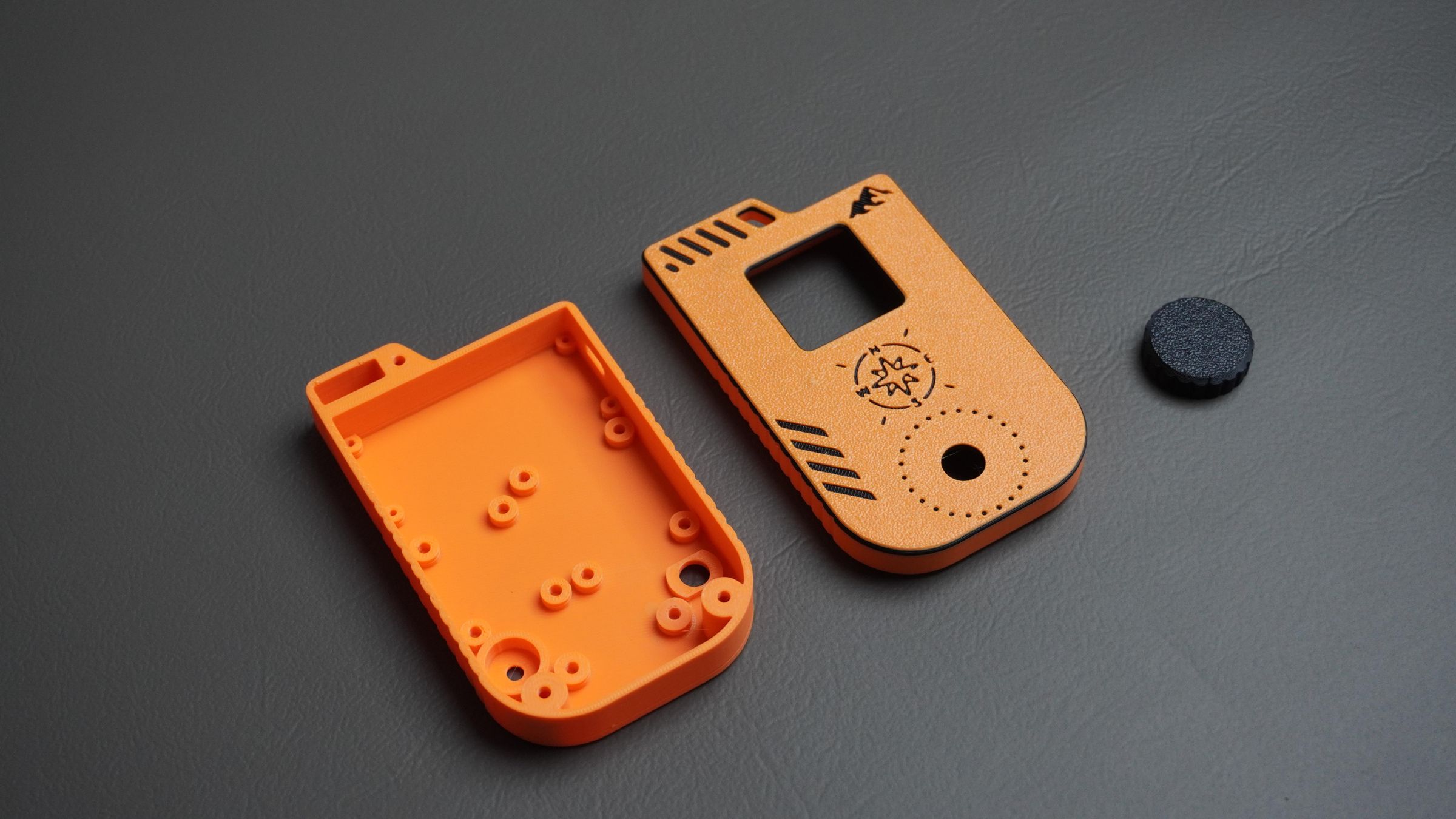
The enclosure consists of three 3D-printed parts:
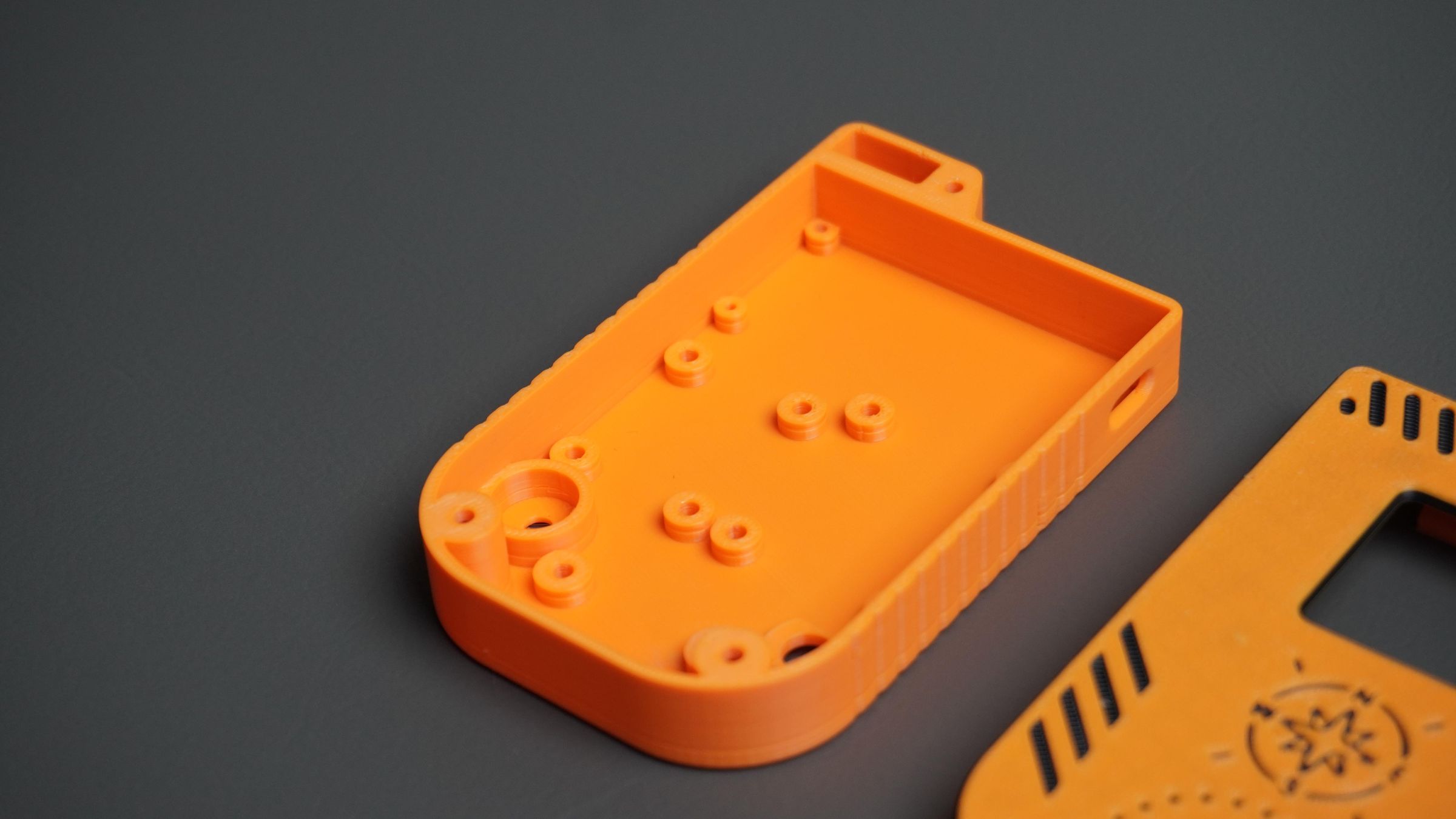
Housing
The main housing contains mounting points for all major components, including:
- FireBeetle 2 ESP32-C6
- GNSS Module
- BMM350 Magnetometer
- Rotary Encoder
- Piezo Buzzer
- Power Switch
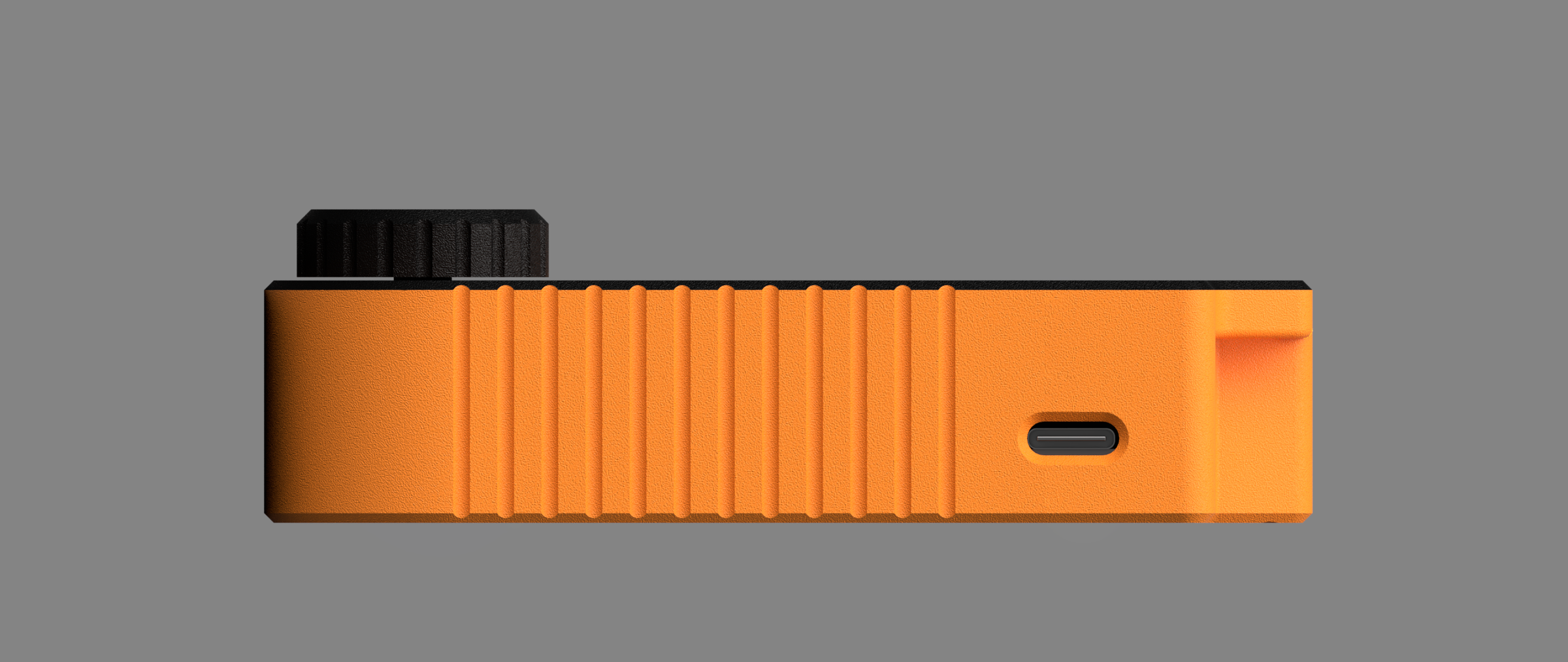
The top section also includes a dedicated mounting area for the GNSS antenna to ensure good satellite reception. An opening is provided on the side for easy access to the ESP32-C6 USB Type-C port for programming and charging.
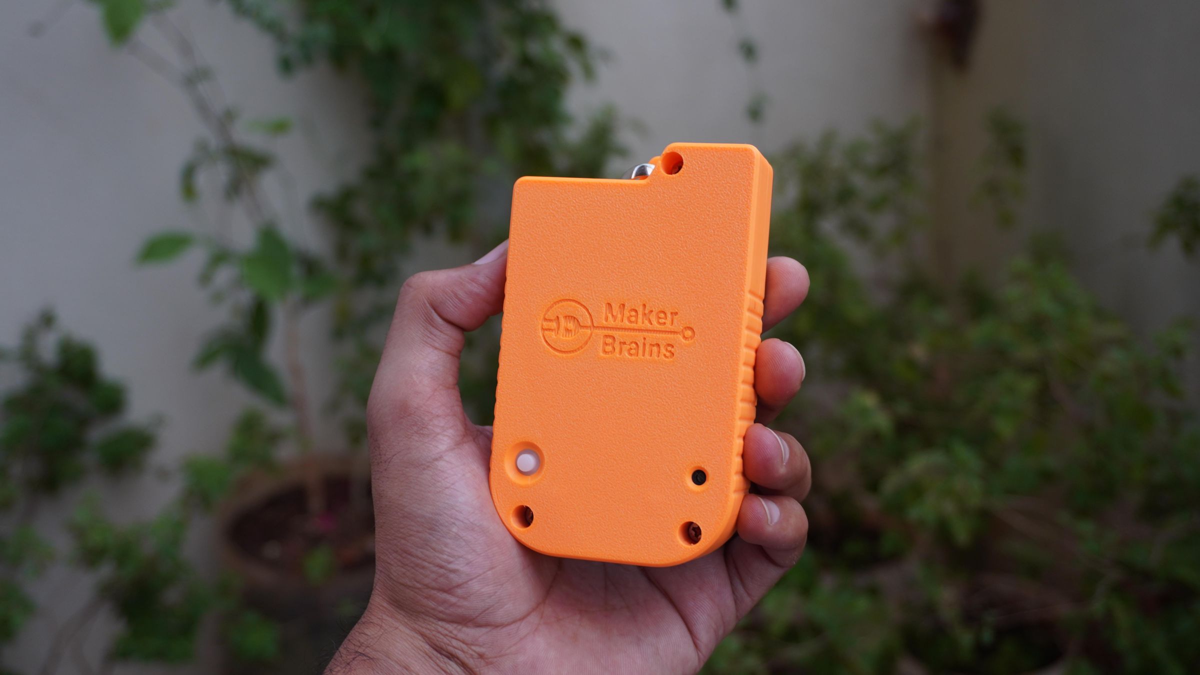
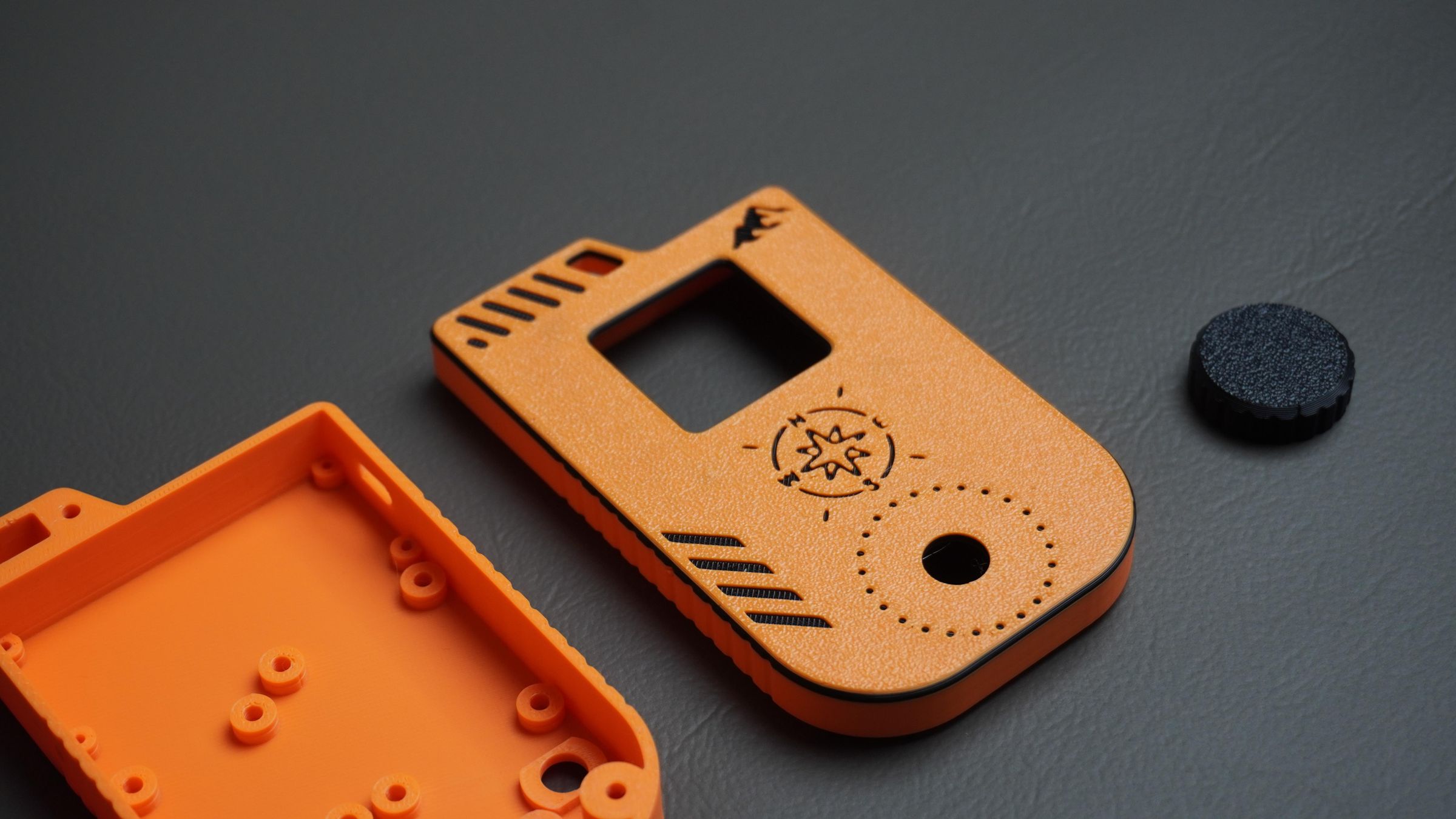
Front Cover
The front cover holds the 1.54" TFT display in place using mounting screws.
It also includes:
- Rotary encoder cutout
- Decorative graphics on the front panel
- Integrated carabiner loop for attaching the navigator to a backpack or gear
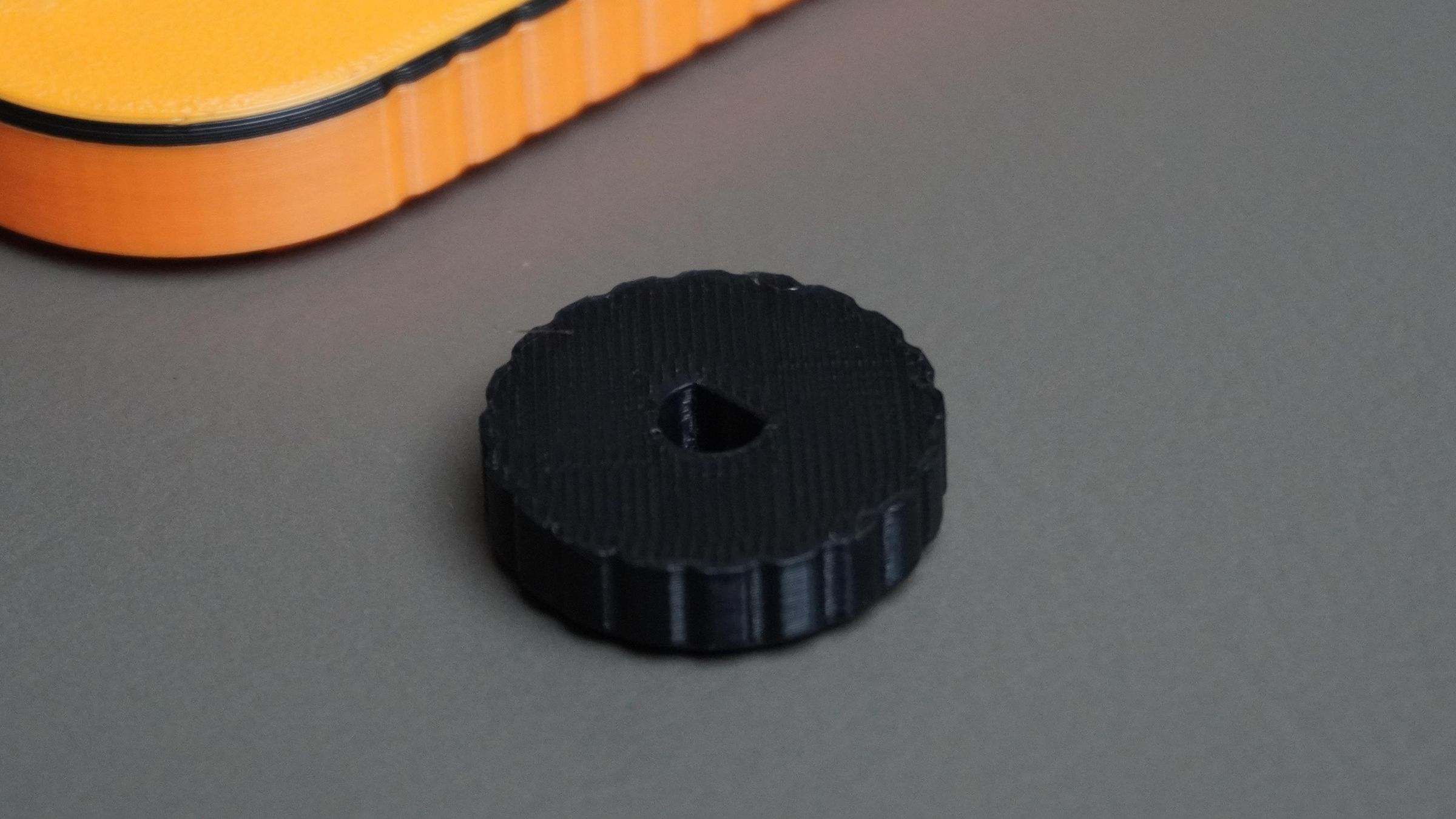
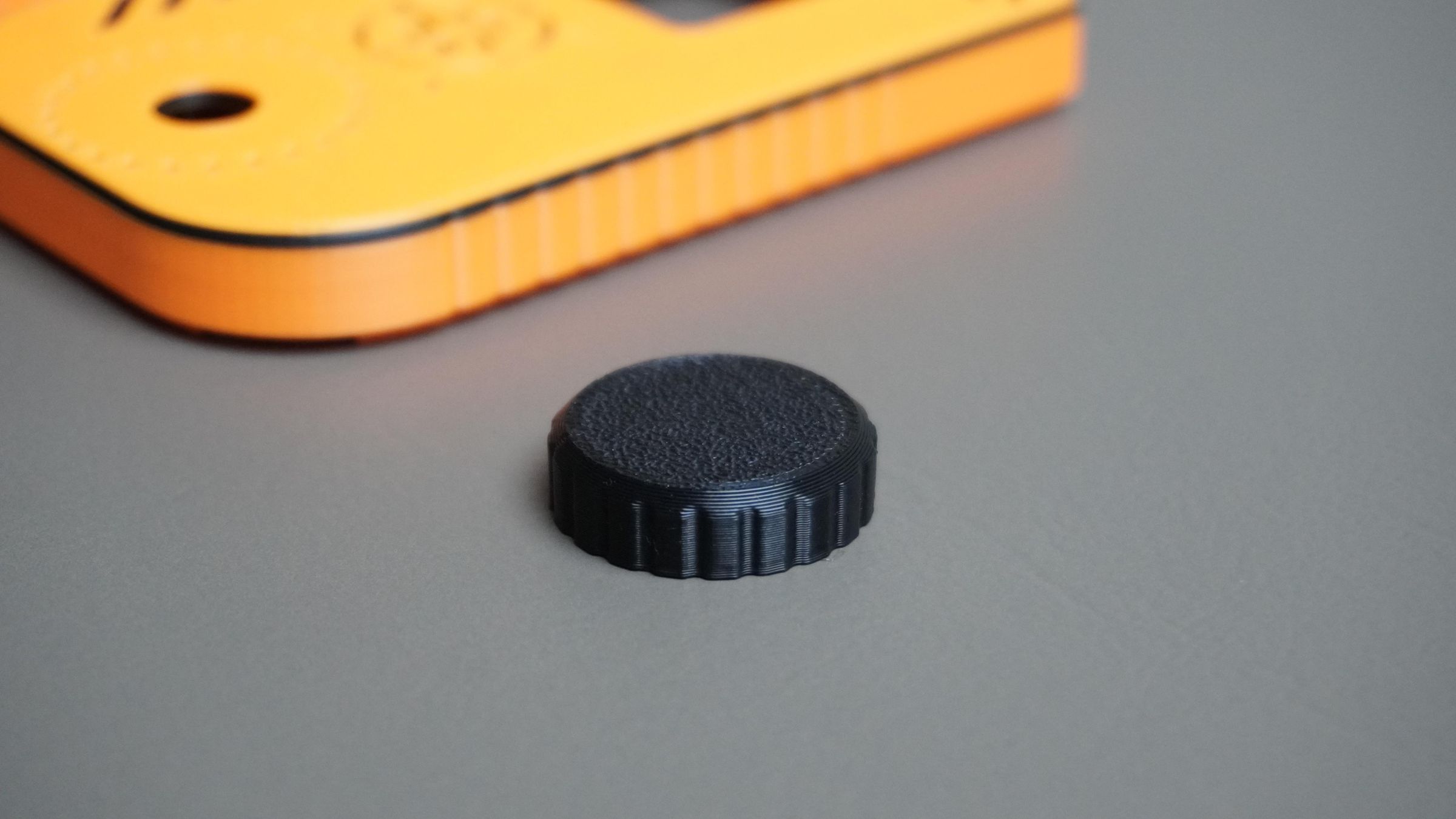
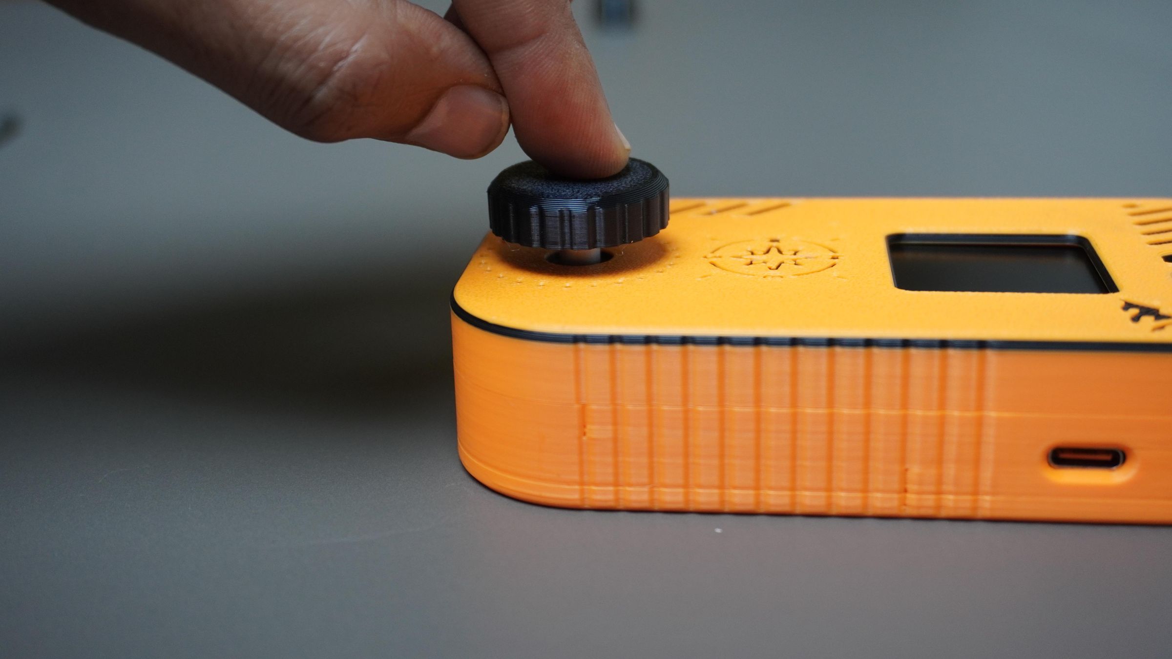
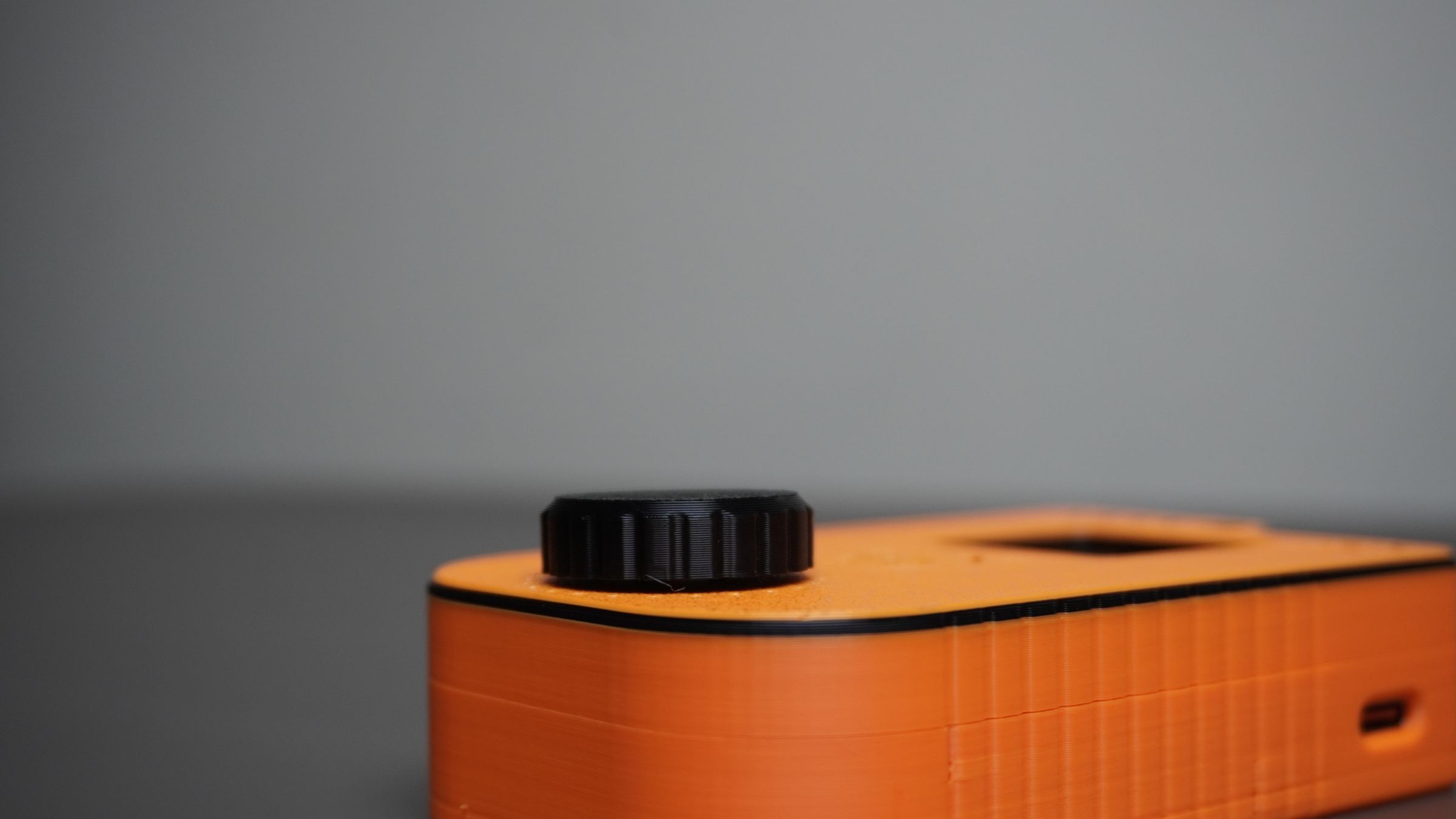
Encoder Knob
The third part is a custom-designed rotary encoder knob that is 3D printed and press-fits onto the encoder shaft.
All enclosure parts were designed to be easy to print without support material and can be modified to fit different hardware configurations if required.
You can download the Fusion 360 design files and STL files from this project and customize them to suit your own requirements.

Step 7: 3D Printing the Parts
With the CAD design complete, it's time to print the enclosure.
For this build, I used:
- Orange PLA for the housing and knob
- Black PLA for the decorative graphics and Knob
Parts to Print
Print the following components:
- 1× Housing
- 1× Front Cover
- 1× Encoder Knob
I printed all parts using standard PLA settings with a 0.4 mm nozzle and 0.2 mm layer height. No special print settings are required, and all parts can be printed without support material.
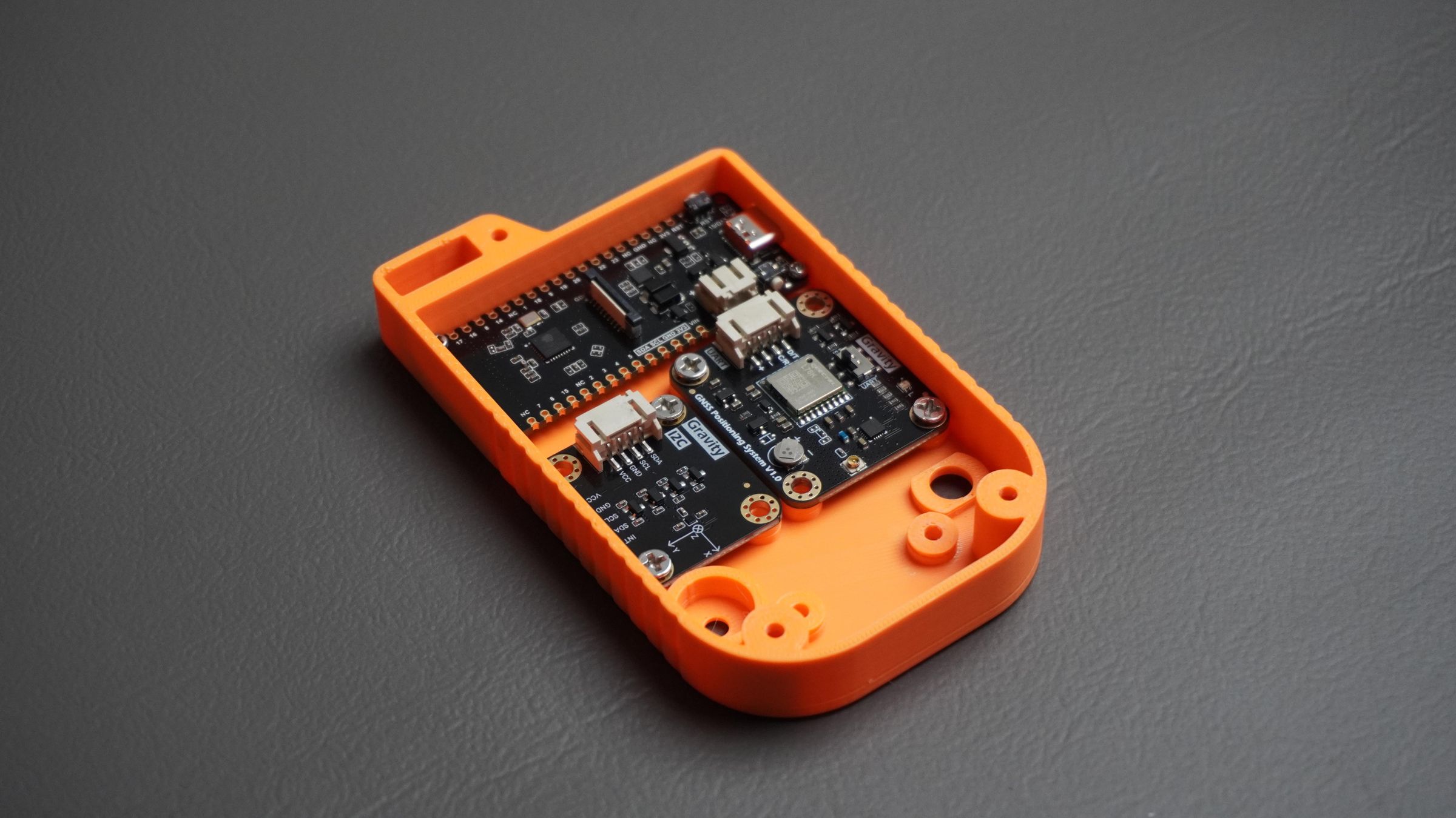
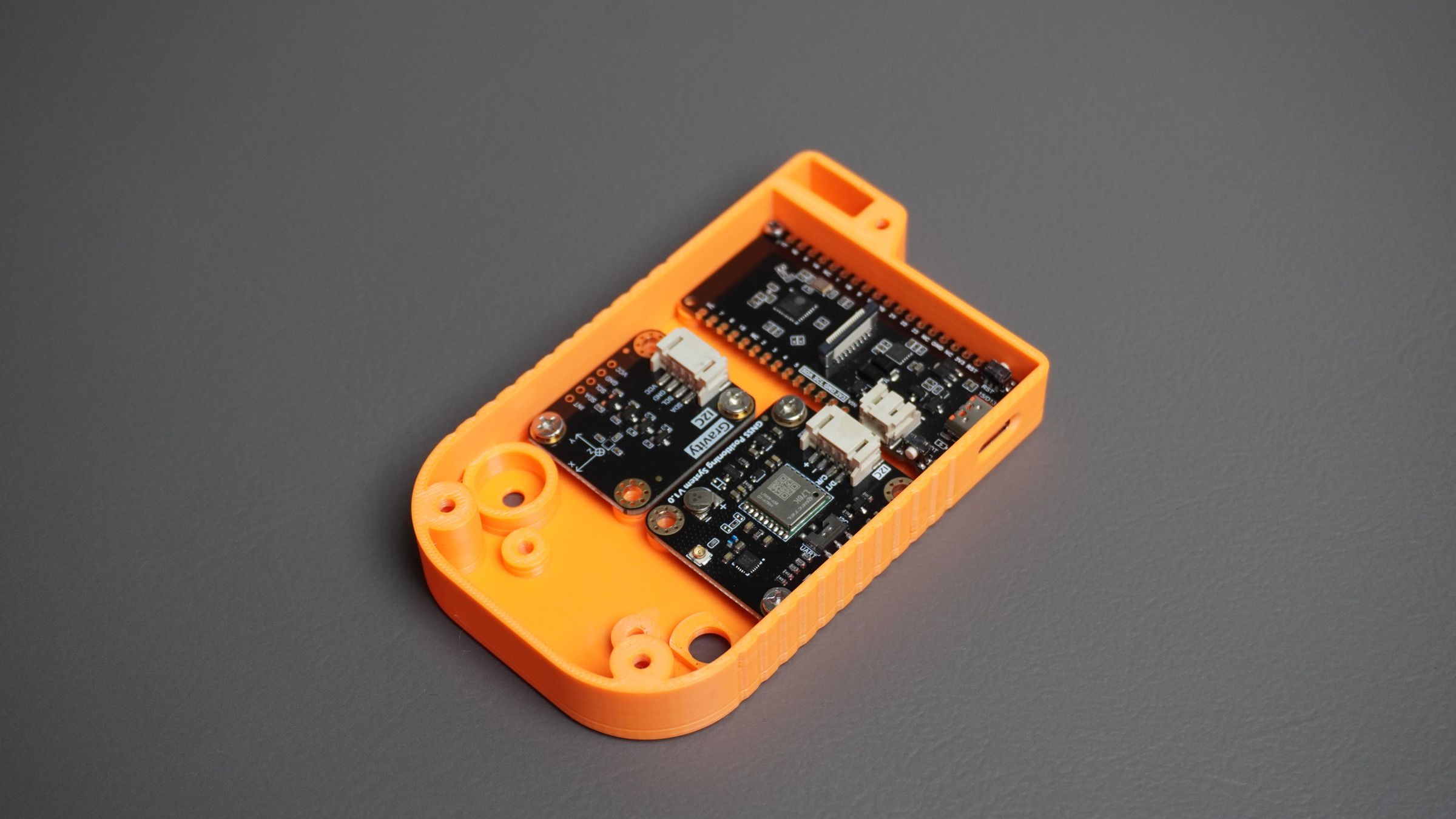
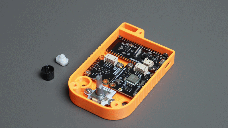
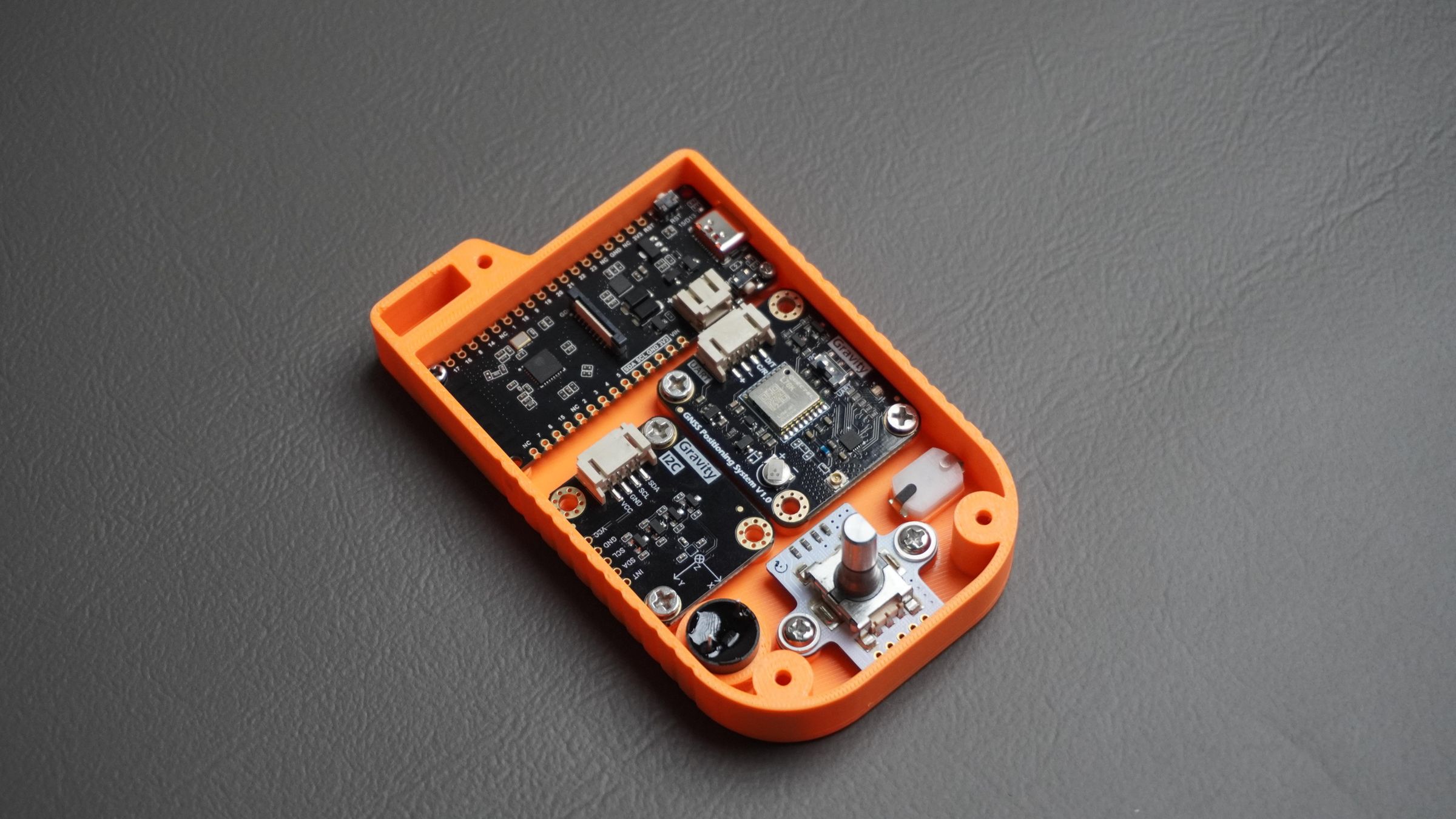
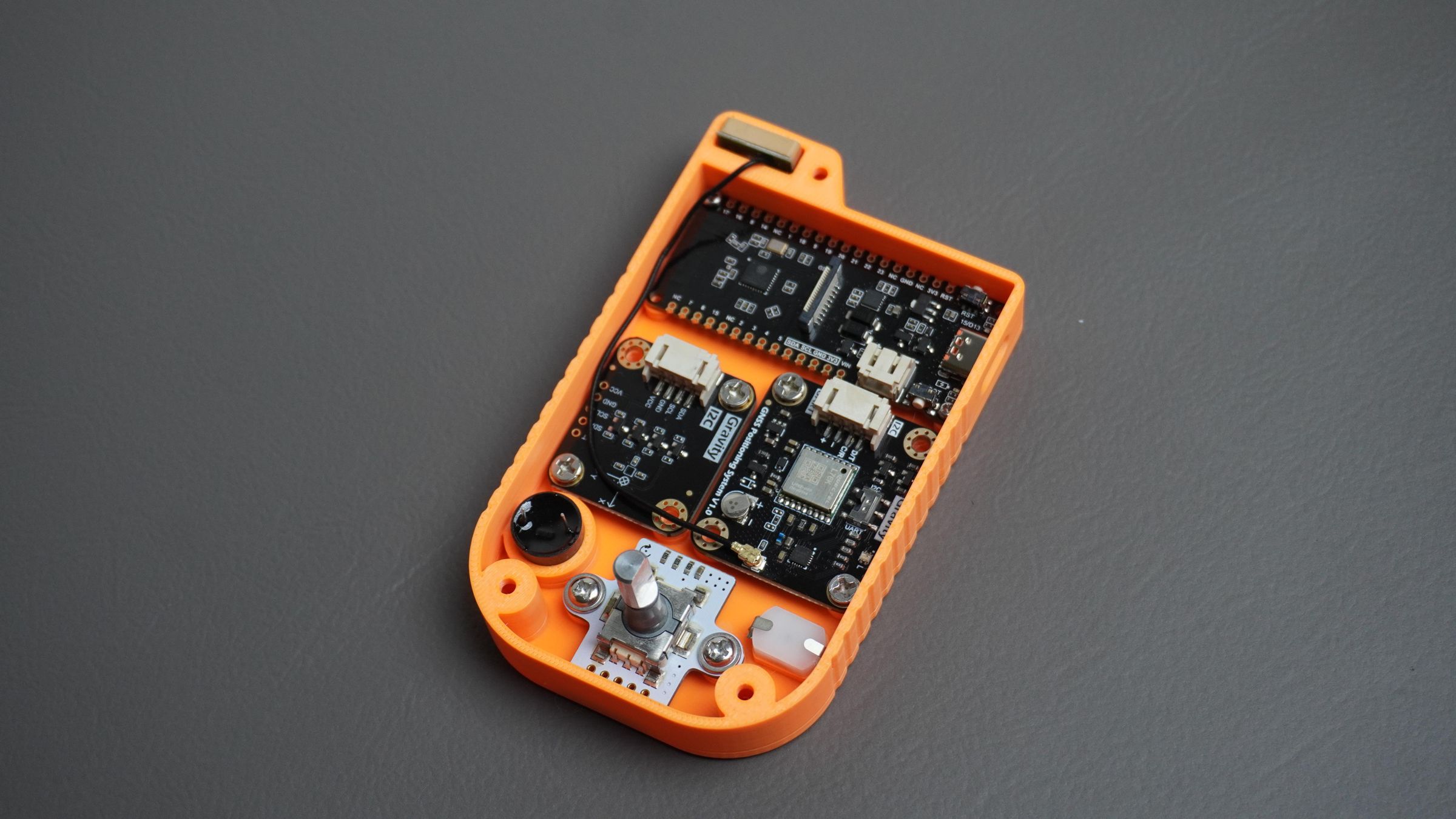
Step 8: Mounting the Modules
With the enclosure printed, it's time to install the electronics into the housing.
Mounting the ESP32-C6:
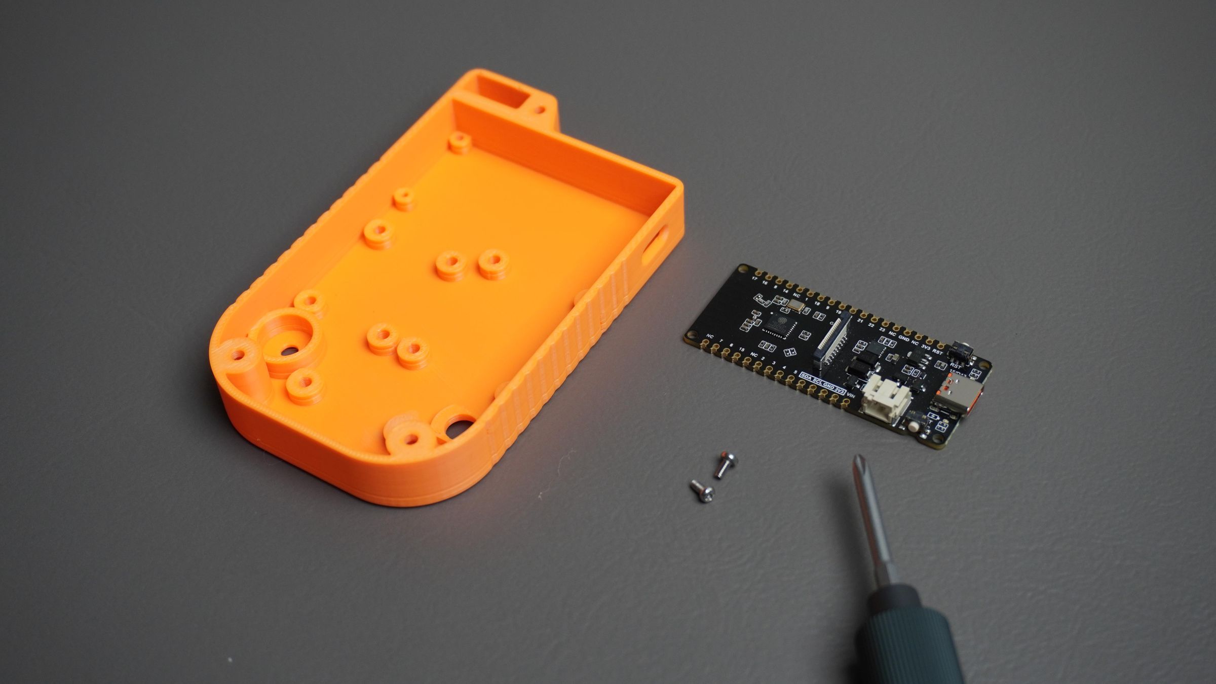
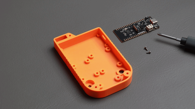
Start by placing the FireBeetle 2 ESP32-C6 into its designated mounting position inside the housing.
Make sure the USB Type-C connector is properly aligned with the opening in the side of the enclosure.
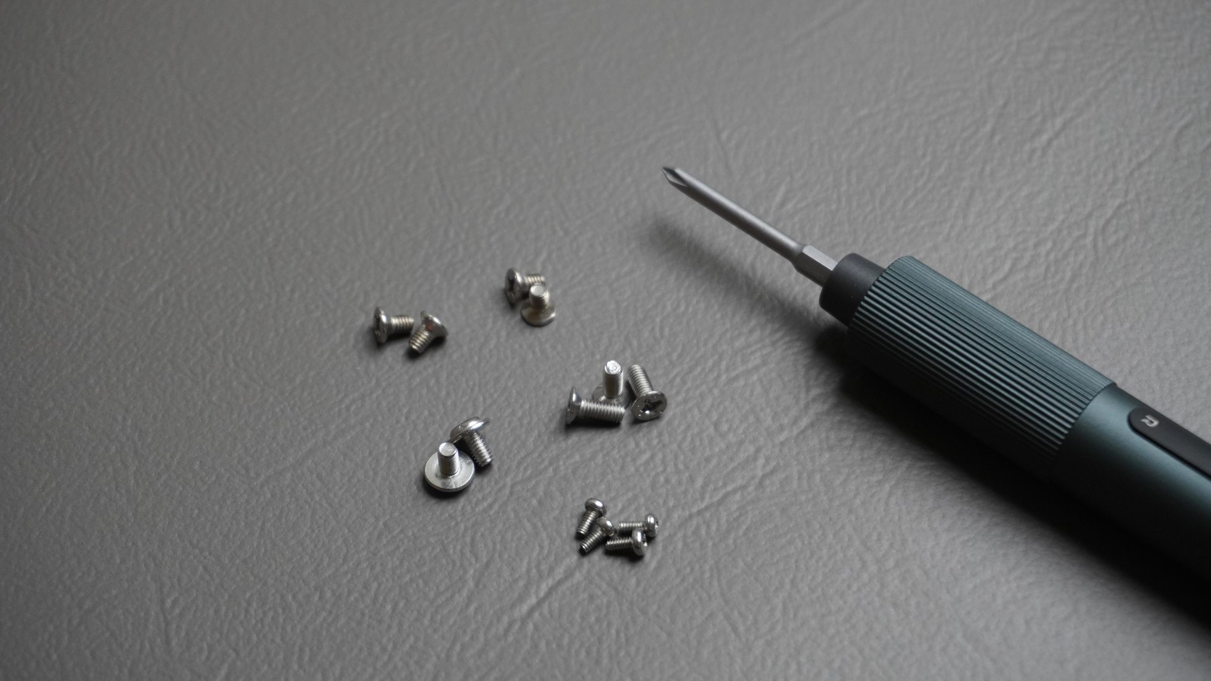
Once aligned, secure the board using:
- 2× M2 screws
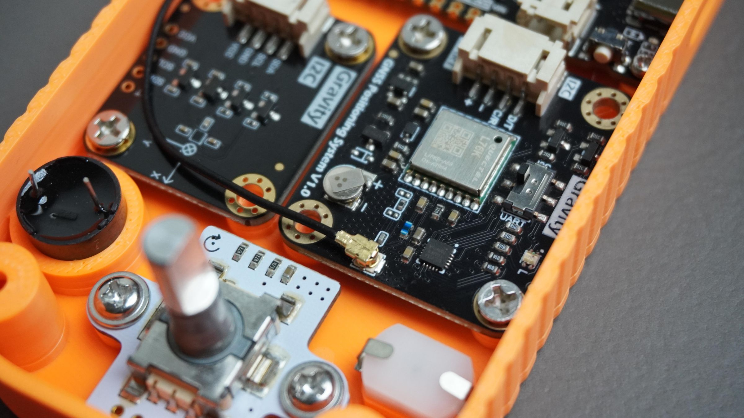
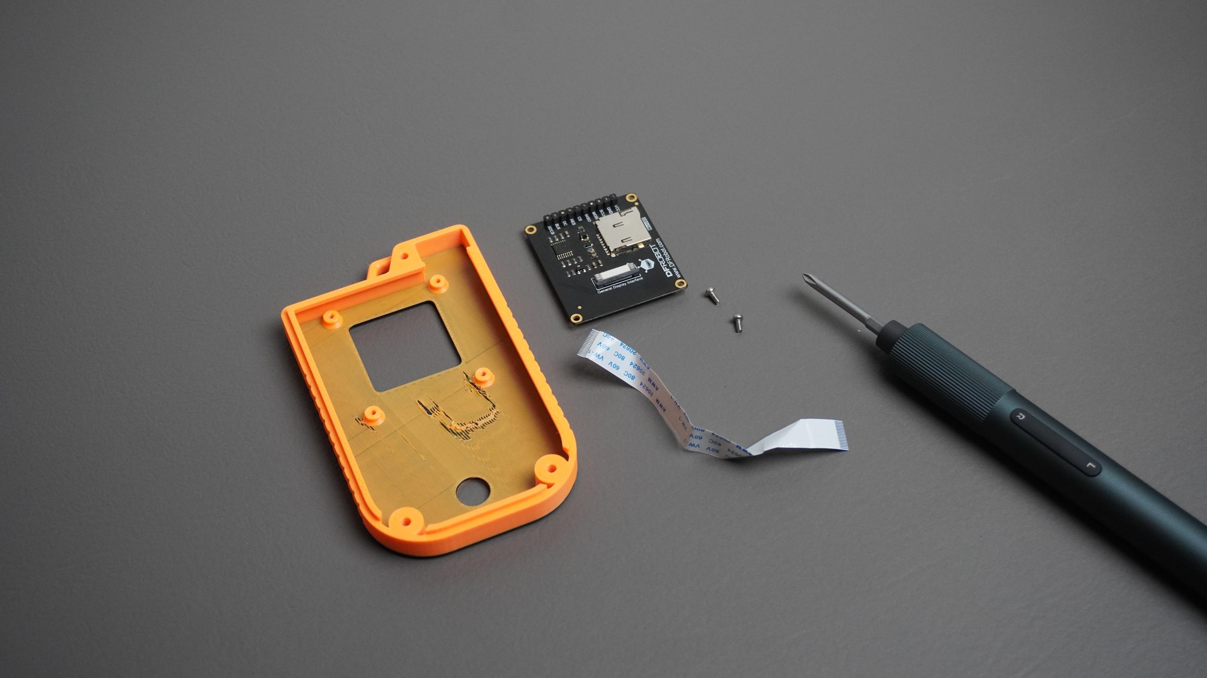
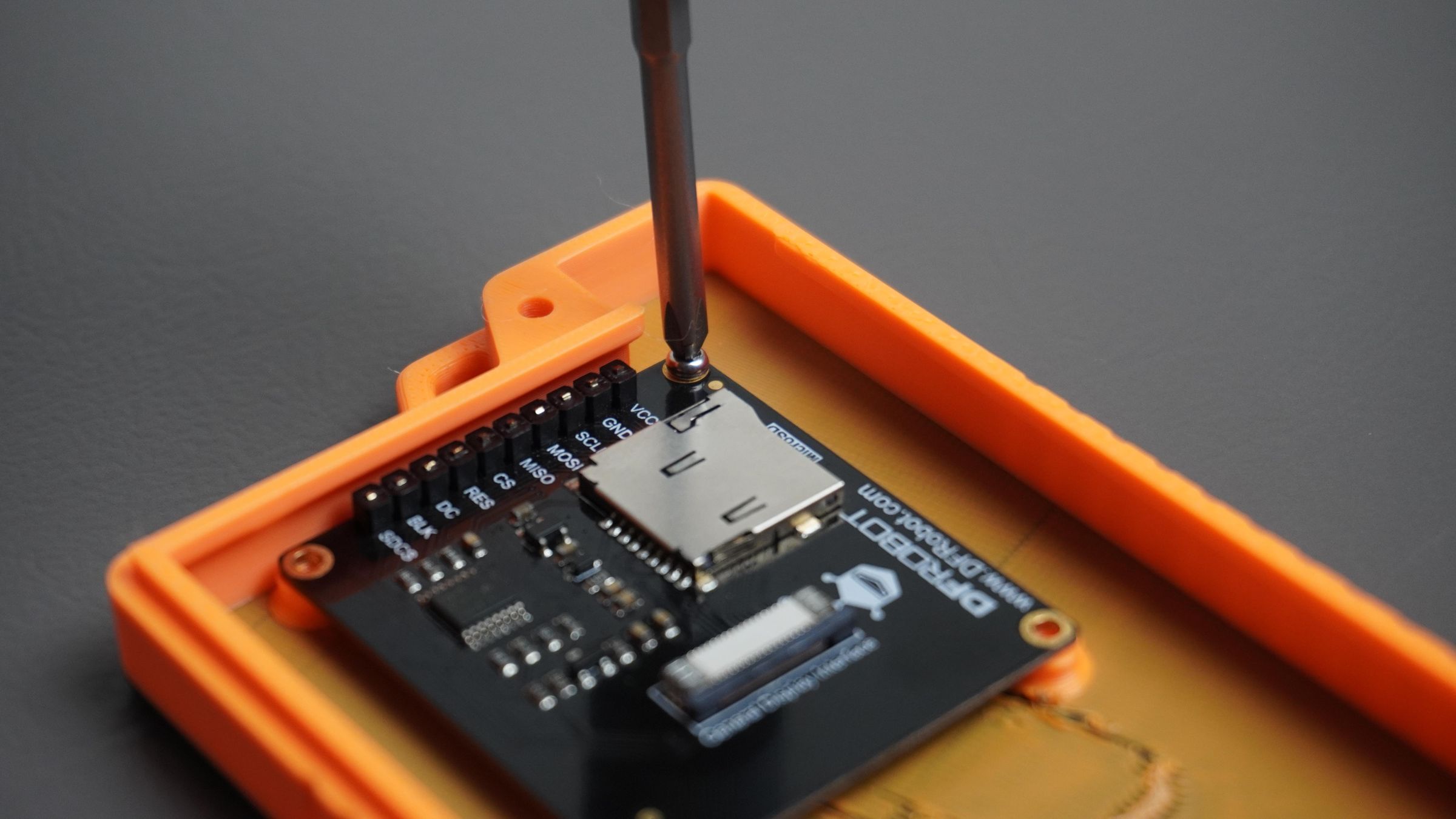
Mounting the GNSS and Magnetometer Modules:
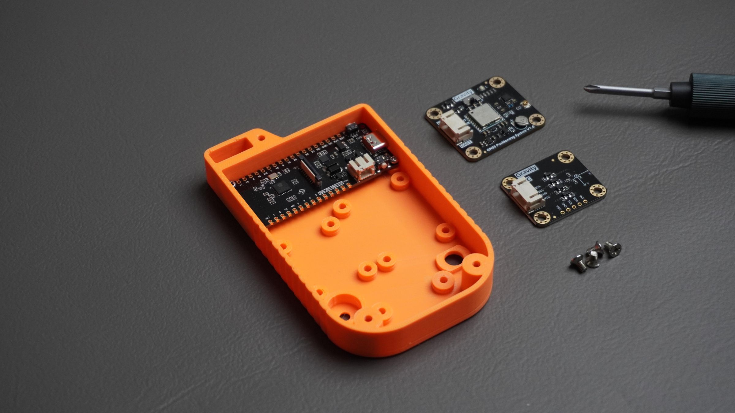
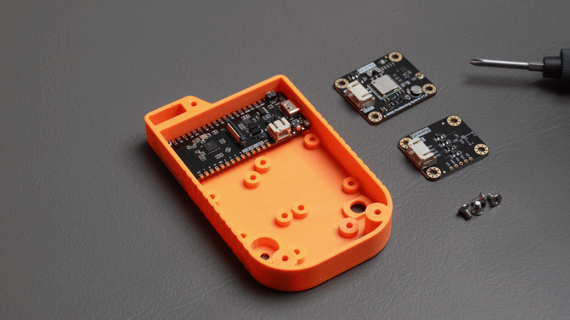
Next, position the GNSS Positioning Module and the BMM350 Magnetometer Module on their respective mounting locations.
Align the mounting holes on each module with the standoffs in the housing and secure them using:
- 2× M3 screws for the GNSS module
- 2× M3 screws for the BMM350 module
Make sure both modules sit flat against the mounting surface before tightening the screws.
Step 9: Mounting the Encoder, Buzzer, and Power Switch
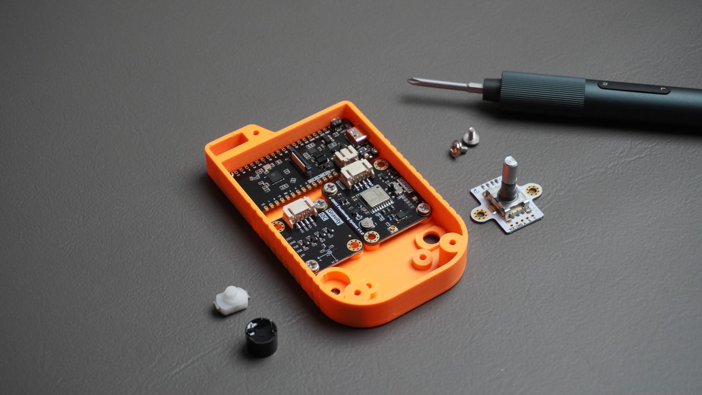
With the main modules installed, it's time to mount the user interface components.
Mounting the Rotary Encoder
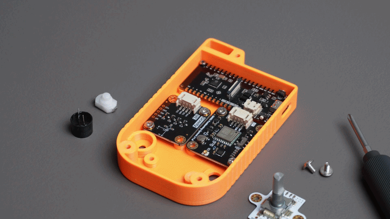
Place the rotary encoder onto the two standoffs provided inside the housing.
Align the mounting holes and secure the encoder using:
- 2× M2 screws
Ensure the encoder shaft is centered in the front panel opening and rotates freely.
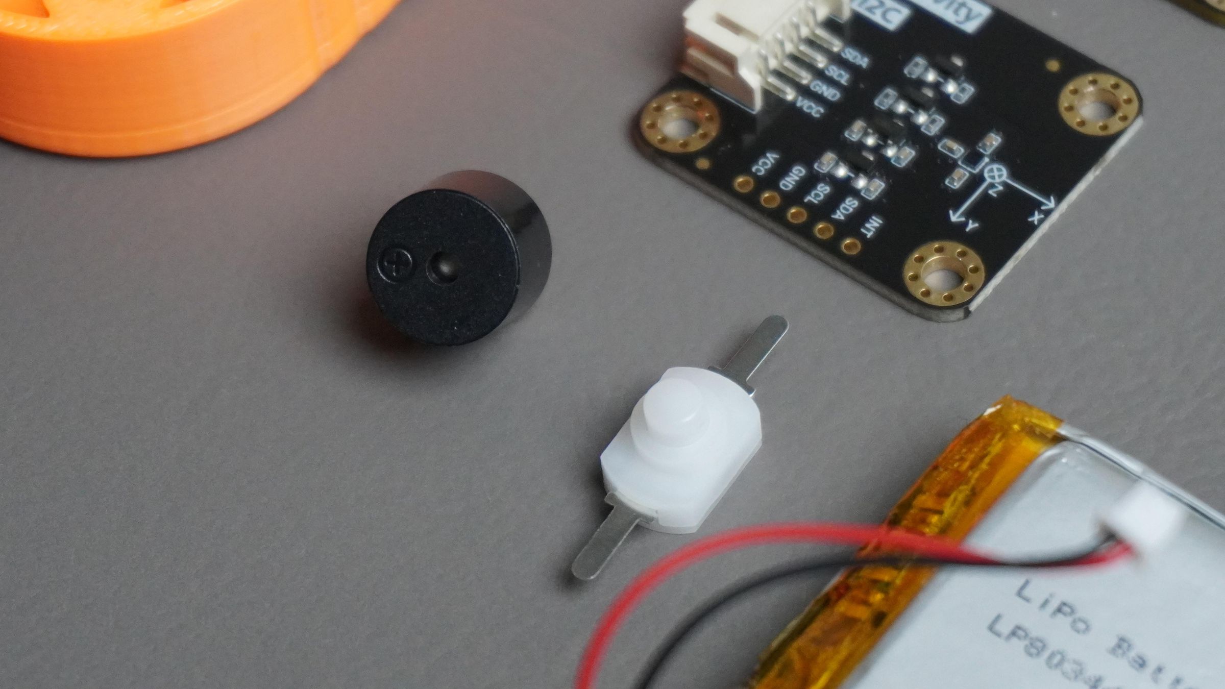
Mounting the Buzzer
- Take the piezo buzzer and gently press it into the dedicated slot designed in the housing.
- The buzzer should fit snugly in place without requiring additional hardware.
Mounting the Power Switch
- Next, insert the power switch into the switch opening on the housing.
- Press it firmly into position until it sits securely in the slot.
- If the switch feels loose, apply a small amount of quick-setting glue to secure it. Be careful not to get glue inside the switch mechanism, as this may affect its operation.
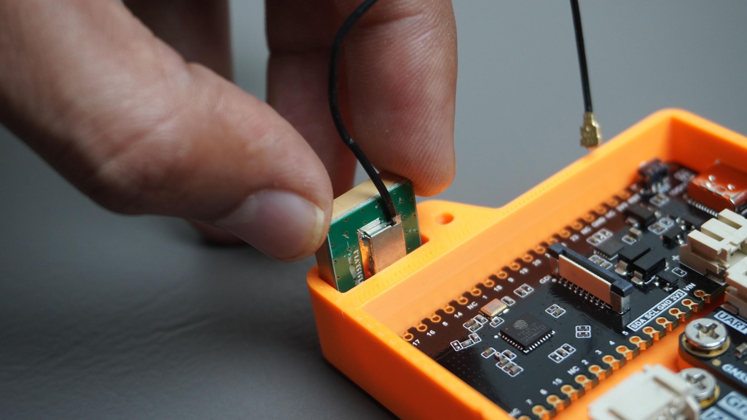
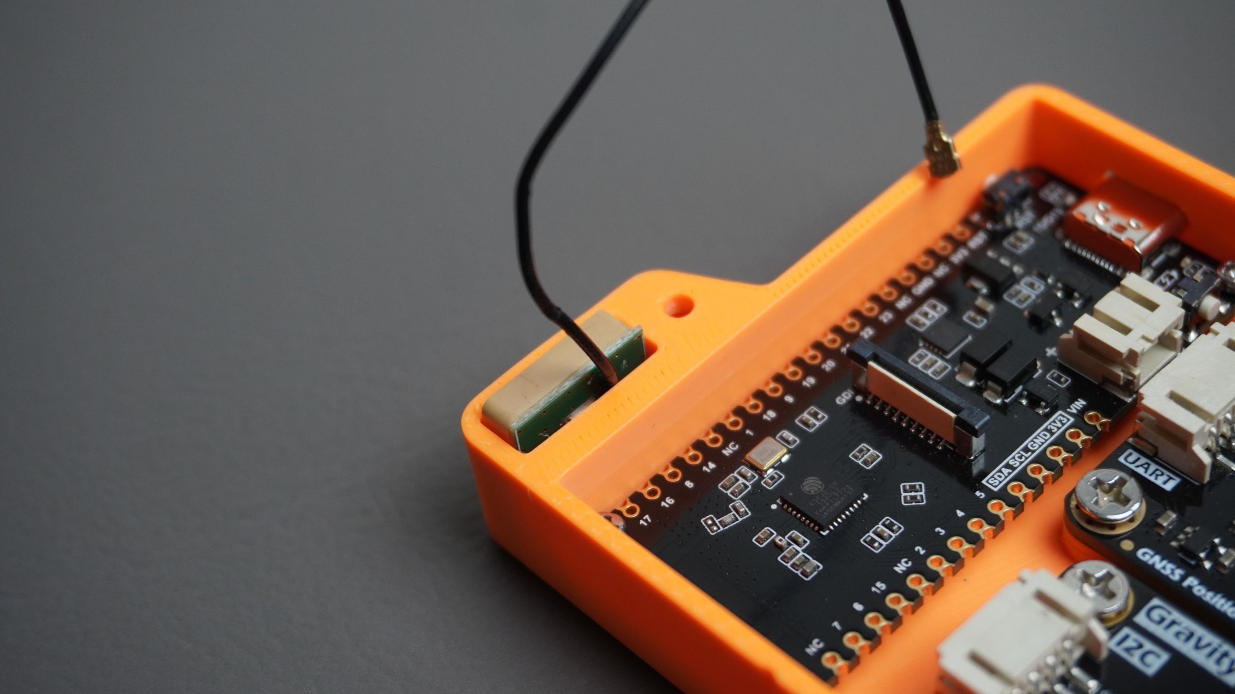
Step 10: Mounting the GNSS Antenna
Place the GNSS antenna into the dedicated antenna compartment in the housing, as shown in the images. The enclosure is designed to hold the antenna securely while keeping it positioned at the top of the device.
Once the antenna is in place, connect the antenna cable to the GNSS module's antenna connector. Press the connector straight down until it clicks into place.
Be careful while attaching the connector, as it is small and delicate. Avoid pulling on the cable itself; always handle it by the connector body.
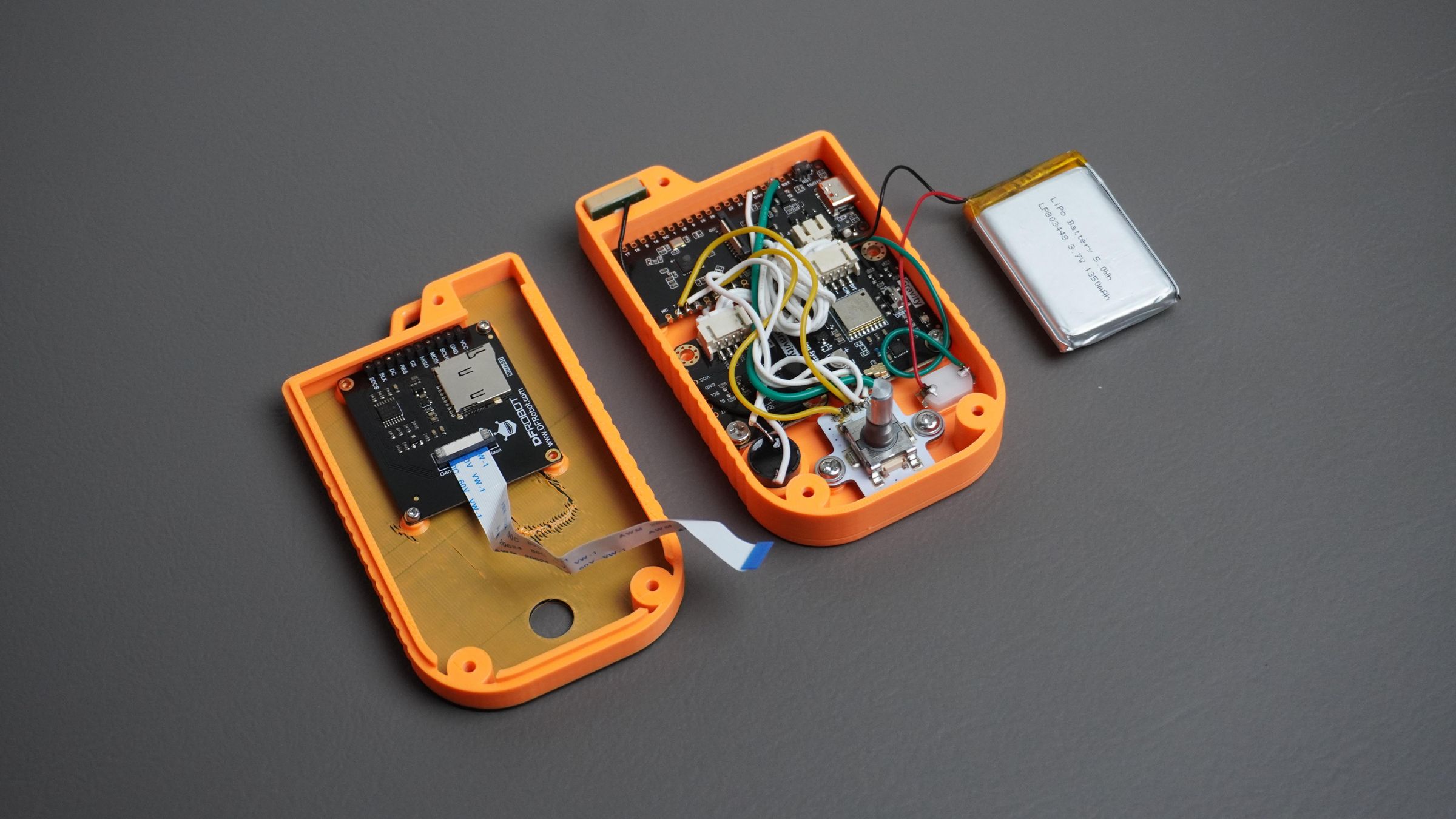
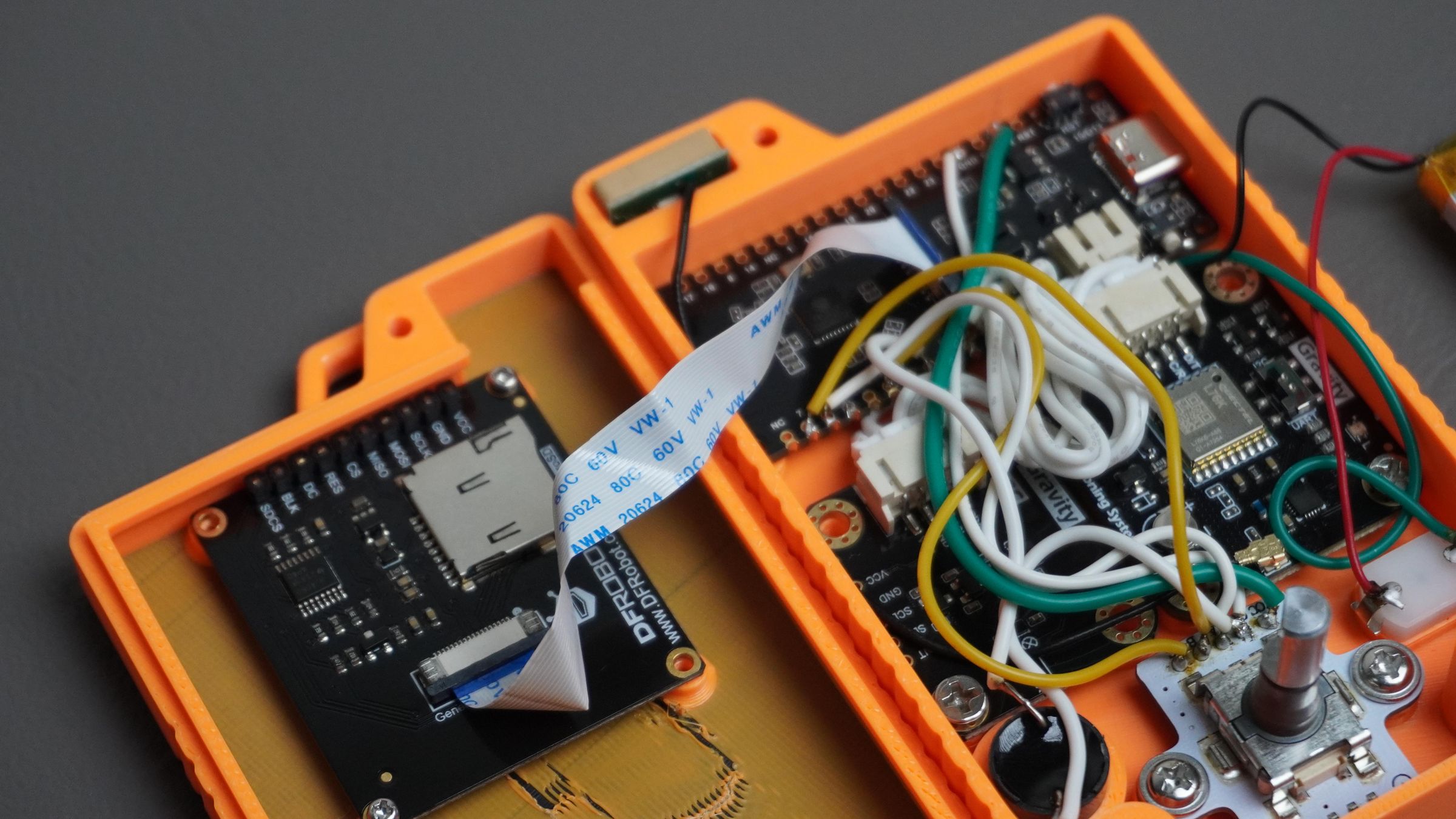
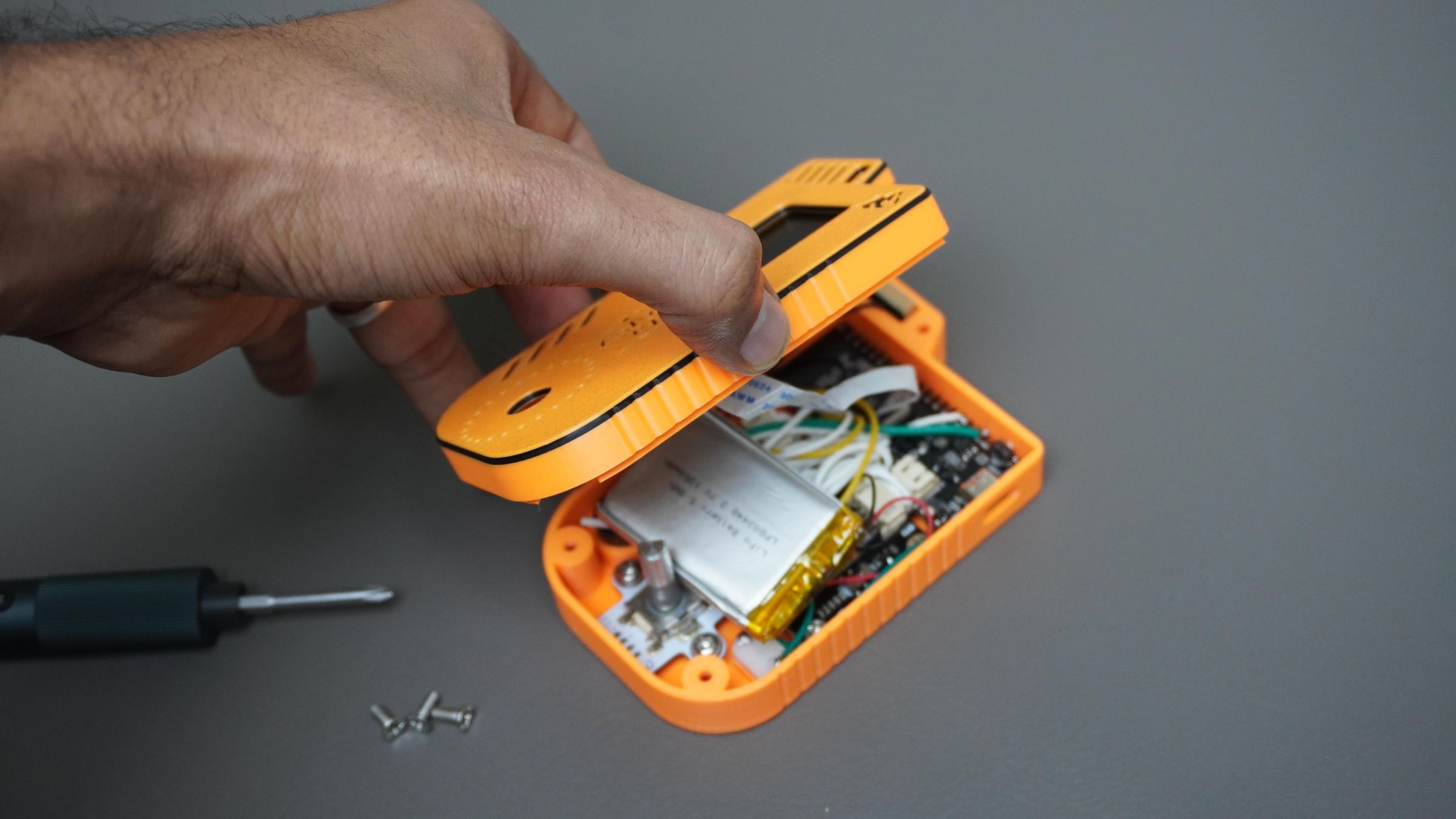
Step 11: Wiring Everything Together
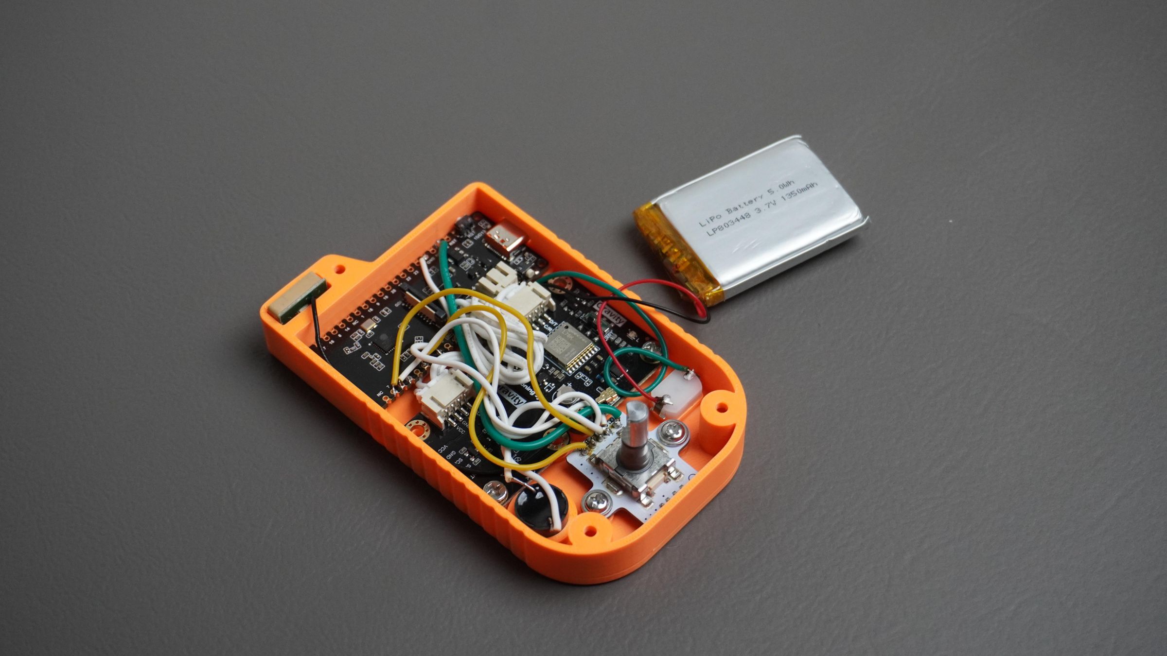
Up to this point, the build has been fairly clean and straightforward. Now comes the part that ties everything together: wiring and soldering.
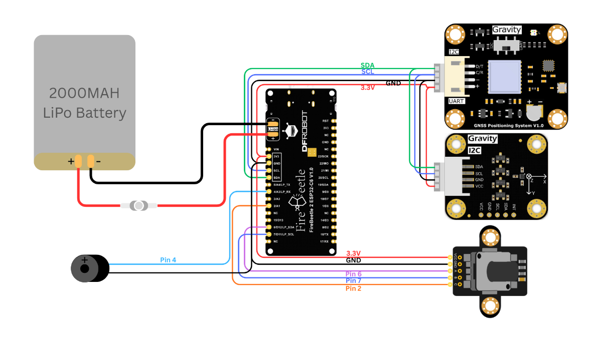
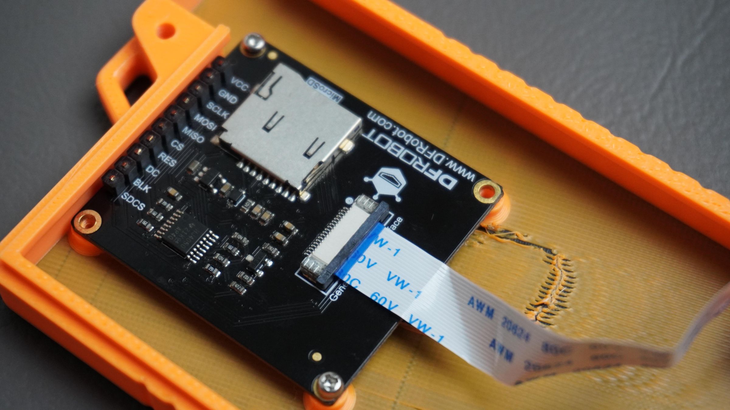
GNSS Module and BMM350 Magnetometer
Both the GNSS receiver and the BMM350 magnetometer communicate with the ESP32-C6 using the I²C interface.
Connect the following pins:
Module to ESP32-C6
- GND~ GND
- VCC~ 3.3V
- SDA~ SDA
- SCL~ SCL
Since both modules use I²C, they can share the same SDA and SCL lines.
Rotary Encoder
Connect the rotary encoder as follows:
Encoder to ESP32-C6
GND~ GND
VCC~3.3V
A~ GPIO 6
B~ GPIO 7
C~ GPIO 2
Buzzer
Connect the piezo buzzer as follows:
Buzzer to ESP32-C6
GND~ GND
Signal (+) ~ GPIO 4
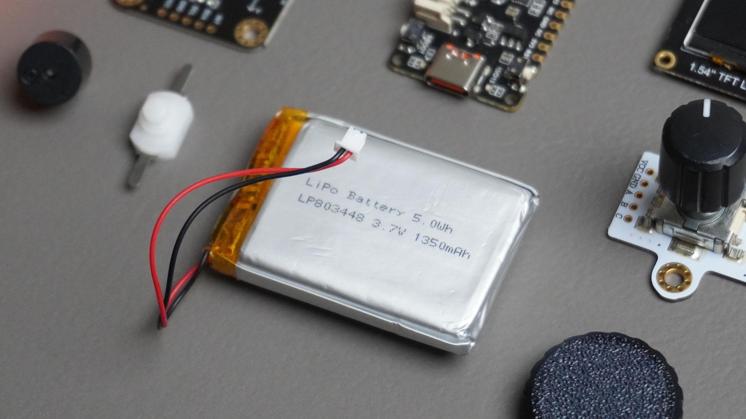
Battery and Power Switch
Connect the LiPo battery to the battery connector on the ESP32-C6.
To allow the device to be switched on and off, place the power switch in series with the battery's positive wire.
Wiring Order:
Battery (+) → Switch → ESP32 Battery (+)
Battery (-) → ESP32 Battery (-)
This allows the switch to disconnect power from the entire system when the device is not in use.
After all connections are complete:
- Check all solder joints.
- Verify there are no shorts between adjacent wires.
- Confirm the battery polarity is correct before powering the device.
- Route wires neatly to prevent interference with the enclosure during final assembly.
Once everything is wired and tested, you're ready to install the display and close the enclosure.
Step 12: Mounting the Display
With all the internal components wired, it's time to install the display into the front cover.
Take the 1.54" TFT display and position it behind the display opening in the front cover. Align the display's mounting holes with the mounting posts provided in the cover.
Once aligned, secure the display using:
- 2× M2 screws
Make sure the display sits flat against the cover and is centered within the display window for the best appearance.
After mounting, the front cover assembly is ready to be connected to the main housing and prepared for final assembly.
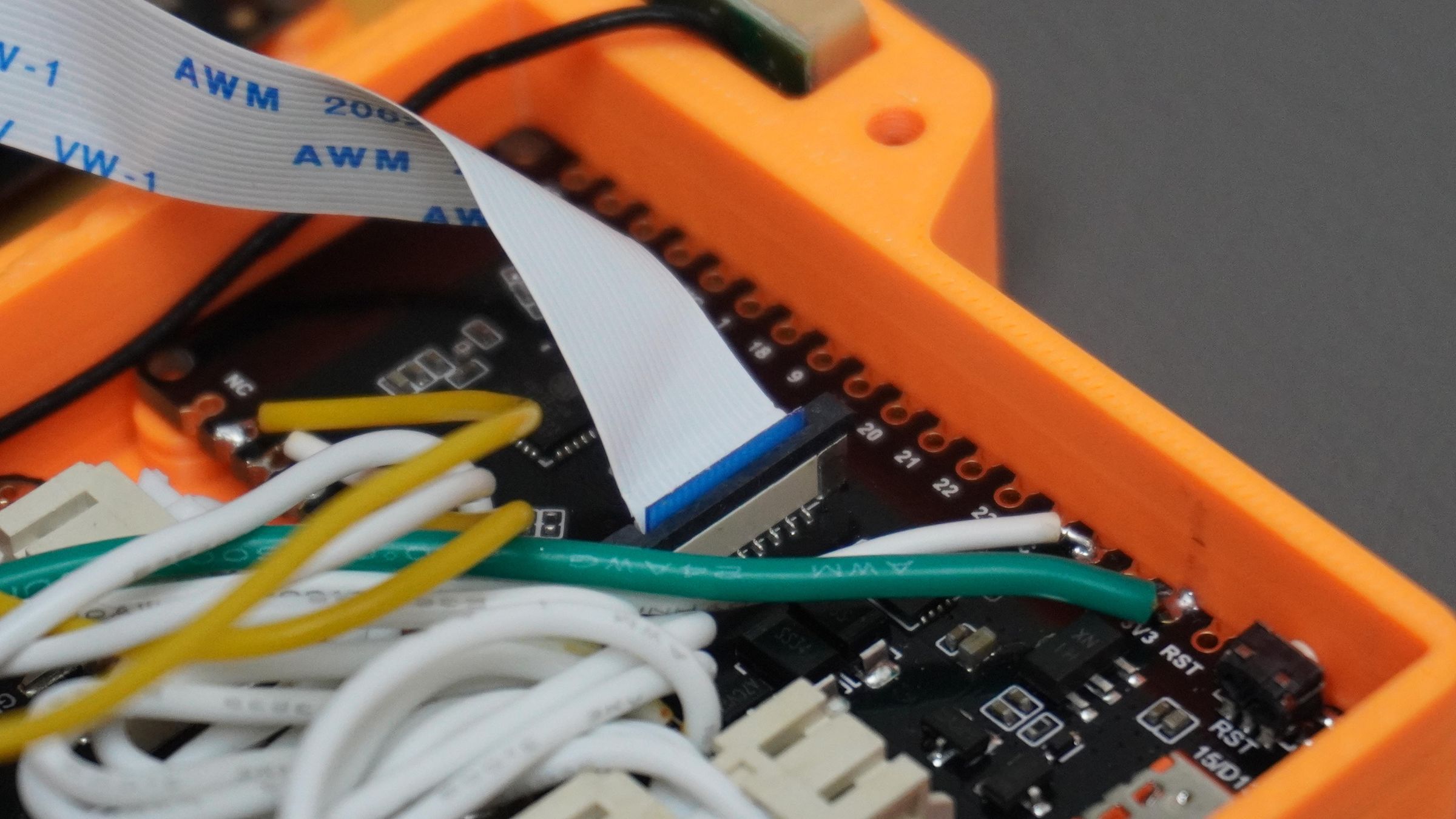
Step 13: Connecting the Display to the ESP32
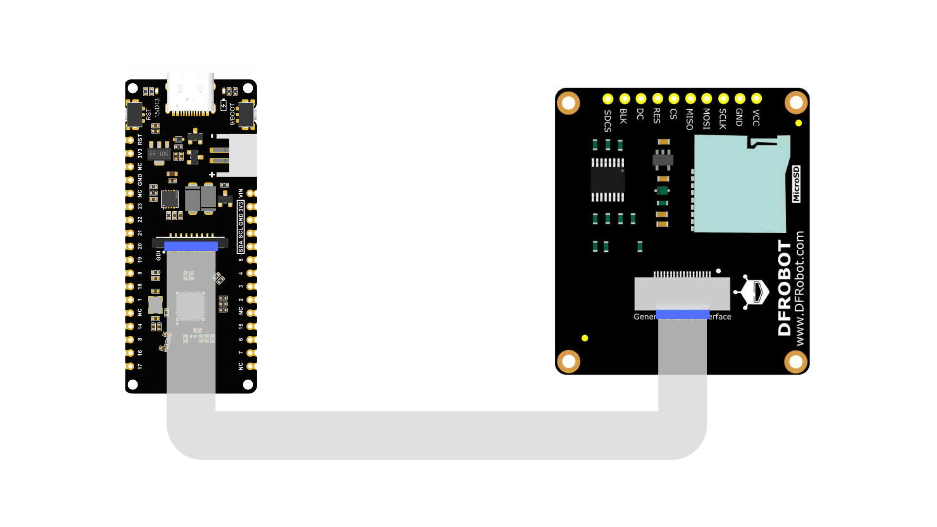
This is one of the easiest steps in the entire build thanks to the GDI (General Display Interface) connector used by the display and the FireBeetle ESP32-C6.
Simply take the GDI cable that came with the display and connect one end to the display and the other end to the GDI port on the ESP32-C6.
Since both power and communication signals are carried through this single cable, no additional wiring is required.
Before connecting the cable, make sure to check the connector orientation carefully and compare it with the reference image. Connecting the cable incorrectly may prevent the display from working properly.
Step 14: Final Assembly
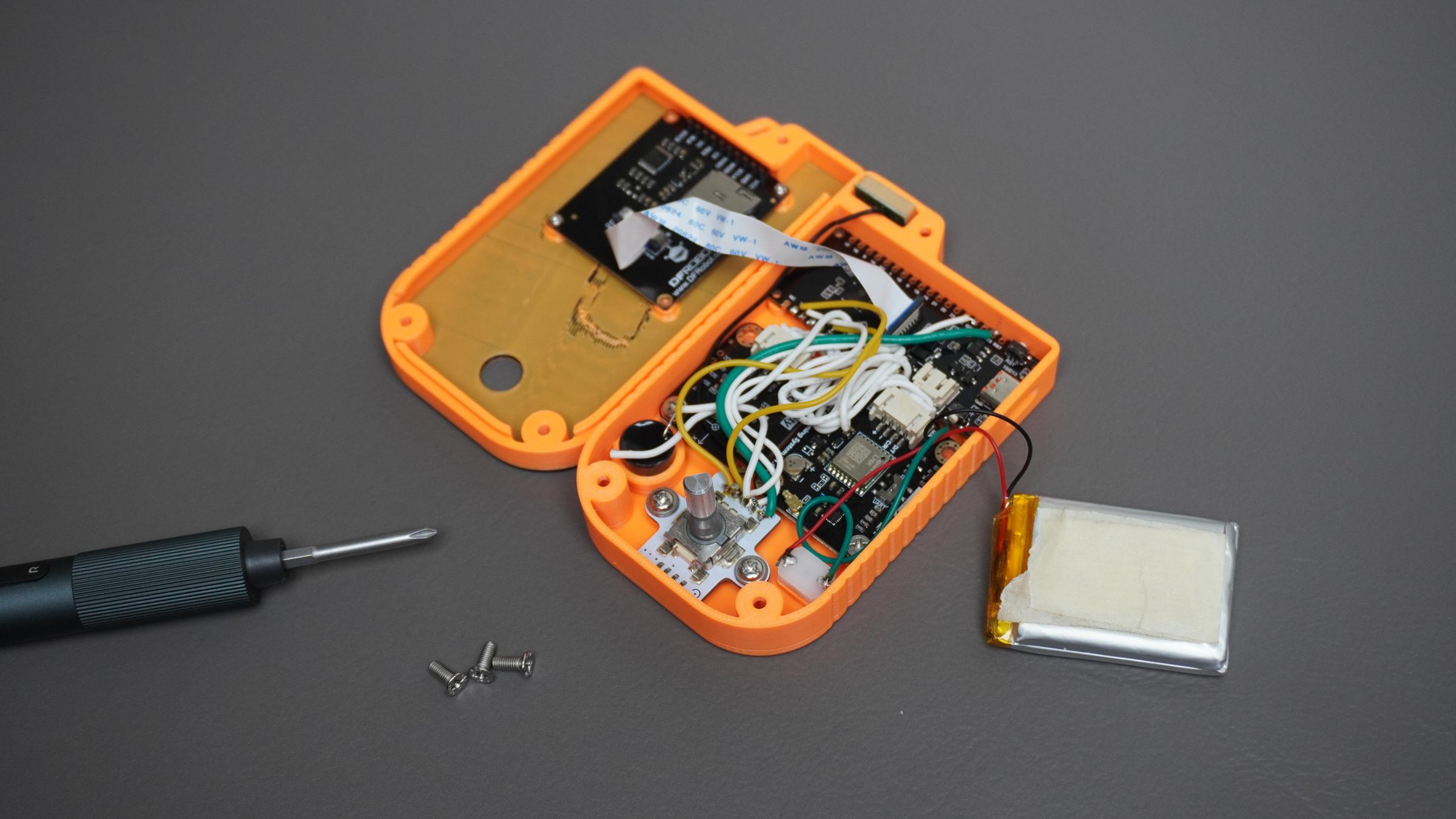
With all the electronics installed and tested, it's time to close the enclosure and complete the build.
Carefully place the LiPo battery into its the housing. Arrange the wires neatly to prevent them from being pinched when the enclosure is closed.
Next, position the front cover onto the housing and check that:
- No wires are trapped between the two parts.
- The display cable is routed safely.
- The encoder shaft passes cleanly through the cover opening.
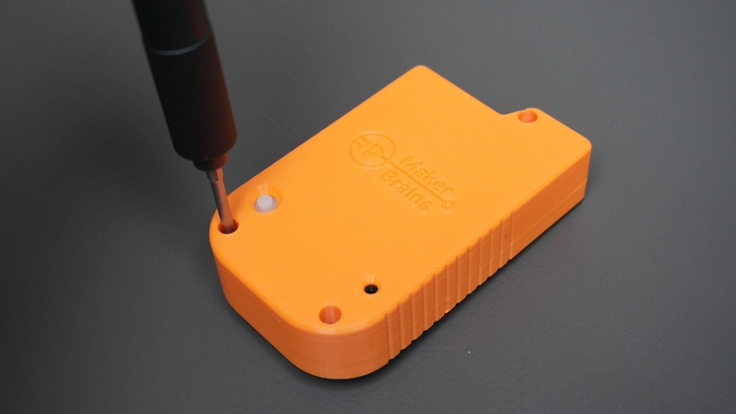
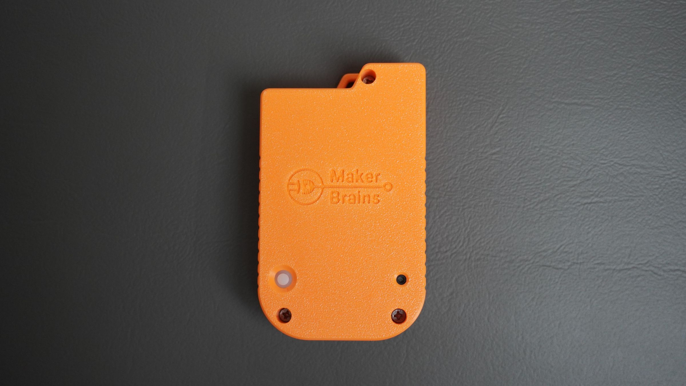
Once everything is aligned, secure the cover using:
- 3× M3 screws
Insert the screws from the back of the cover and tighten them evenly until the enclosure is firmly closed.
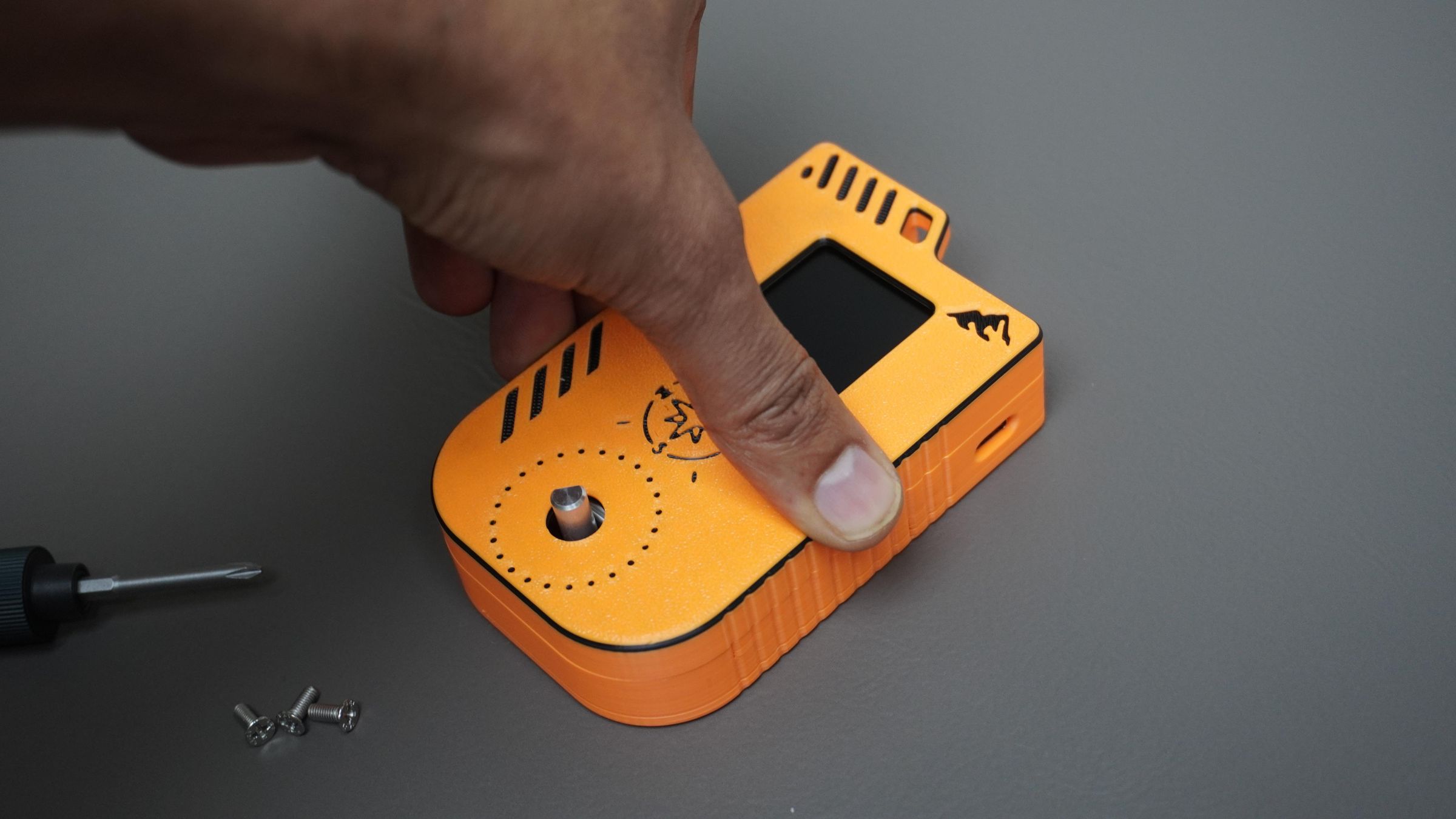
After assembly, install the 3D-printed encoder knob onto the encoder shaft and verify that it rotates smoothly.
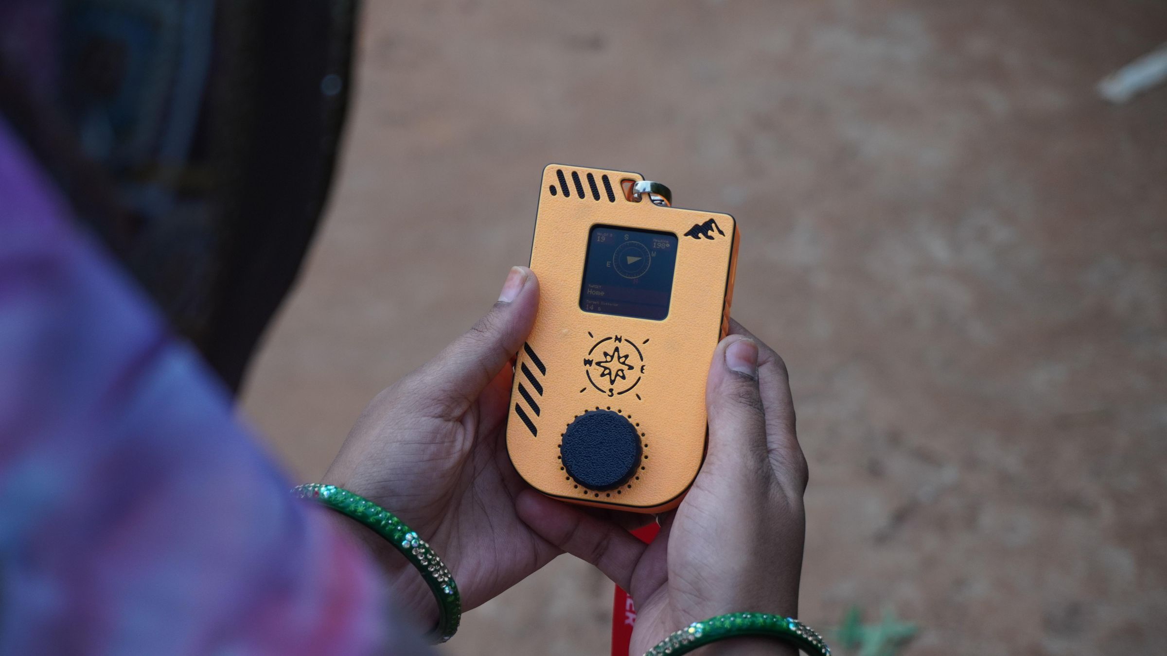
Your DIY Pathfinder is now fully assembled and ready for power-up, configuration, and field testing.
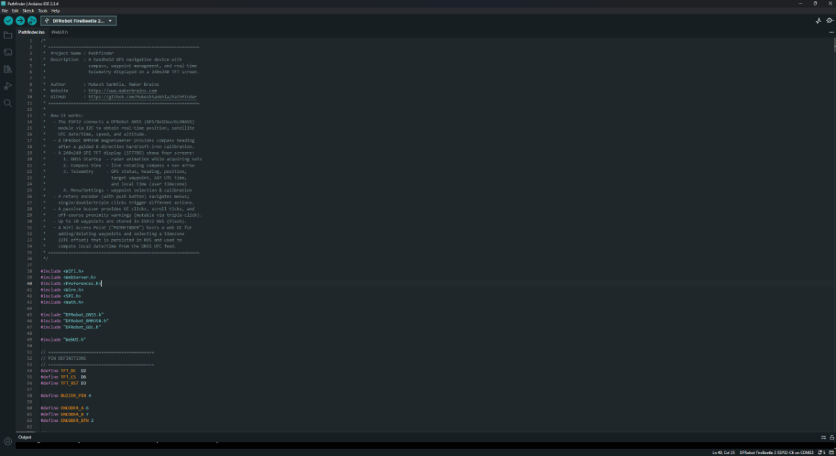
Step 15: Flashing the Firmware
With the hardware assembled, the final step is to upload the Pathfinder firmware to the ESP32-C6.
Download the Pathfinder Firmware:
Before uploading the code, download the latest Pathfinder firmware from GitHub: Pathfinder GitHub Repository
- Download the zip.
- Extract the ZIP file.
- Open the Pathfinder.ino project in Arduino IDE.
Install Arduino IDE: If you don't already have it installed, download and install the Arduino IDE from the official website:
- Download Arduino IDE
- Install it using the default settings
Install the ESP32 Board Package:
- Open Arduino IDE
- Go to File → Preferences
- In Additional Boards Manager URLs, add:
https://espressif.github.io/arduino-esp32/package_esp32_index.json- Click OK
- Go to Tools → Board → Boards Manager
- Search for ESP32
- Install ESP32 by Espressif Systems
Install Required Libraries
DFRobot GNSS Library:
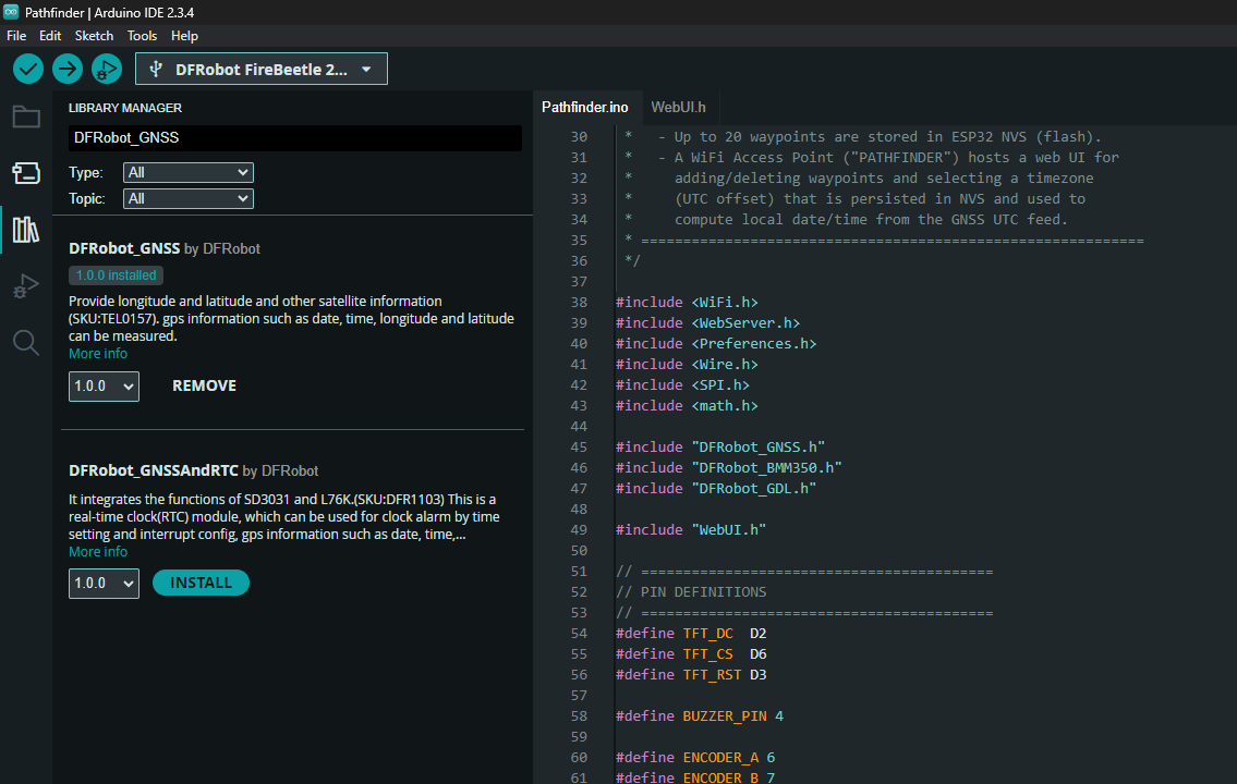
- Open Library Manager
- Sketch → Include Library → Manage Libraries
- Search for:
DFRobot_GNSS- Click Install
DFRobot GDL Display Library:
.png)
Search for:
DFRobot_GDLand install the latest version.
Install the BMM350 Library:
The BMM350 library must currently be installed manually.
- Visit the DFRobot BMM350 GitHub repository: DFRobot BMM350 GitHub Repository
- Click Code → Download ZIP
- In Arduino IDE go to: Sketch → Include Library → Add .ZIP Library
- Select the downloaded ZIP file.
The library will now be added to your Arduino installation.
Select the Correct Board:
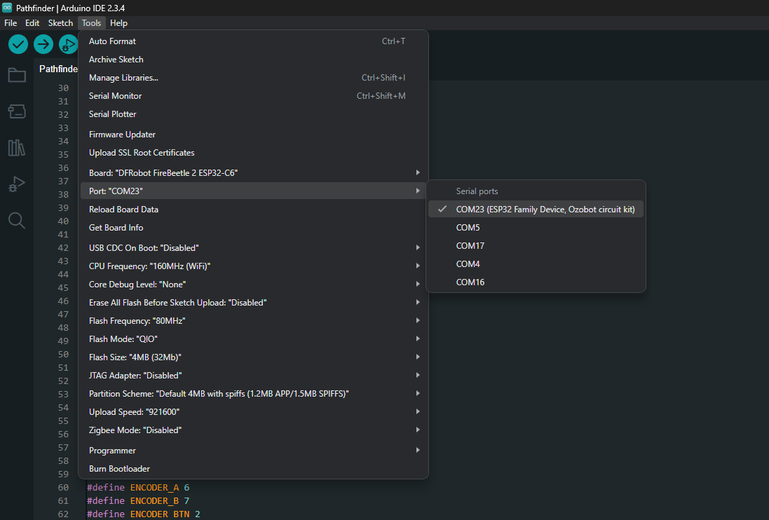
Connect the FireBeetle 2 ESP32-C6 to your computer using a USB Type-C cable.
Then configure Arduino IDE:
- Board: DFRobot FireBeetle 2 ESP32-C6
- Port: Select the COM port corresponding to your device
- Click Upload.
- Wait for compilation and flashing to complete.
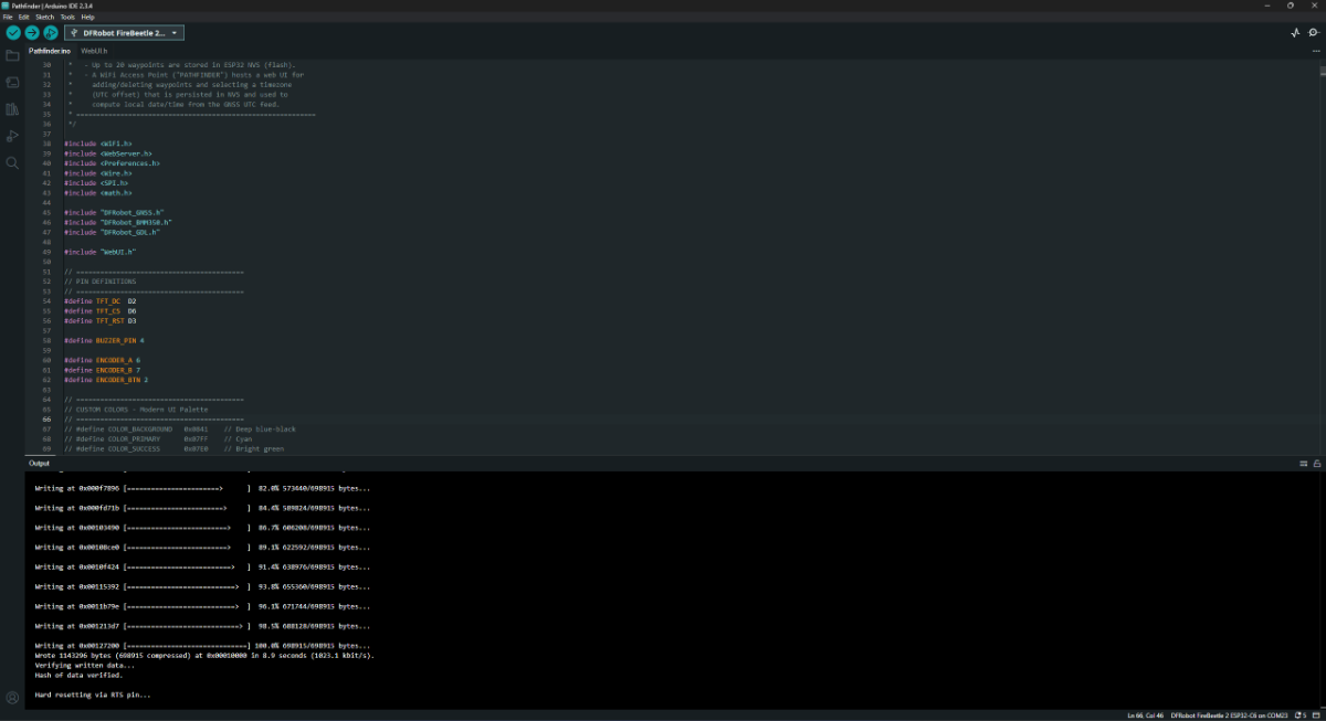
Once the upload finishes successfully, the Pathfinder will reboot automatically and display the startup screen.
Step 16: Connect to the Access Point and Configure Pathfinder
With the firmware flashed, it's time to configure your Pathfinder.
Connect to the Pathfinder Wi-Fi Network:
Power on the Pathfinder using the power switch.
After booting, the device will create its own Wi-Fi access point.
- Open the Wi-Fi settings on your phone or computer.
- Look for the Pathfinder hotspot.
- Connect using the password:
X123456789
Open the Configuration Portal:
Once connected to the Pathfinder network, open a web browser and navigate to:
192.168.0.4You should see the Pathfinder configuration interface.
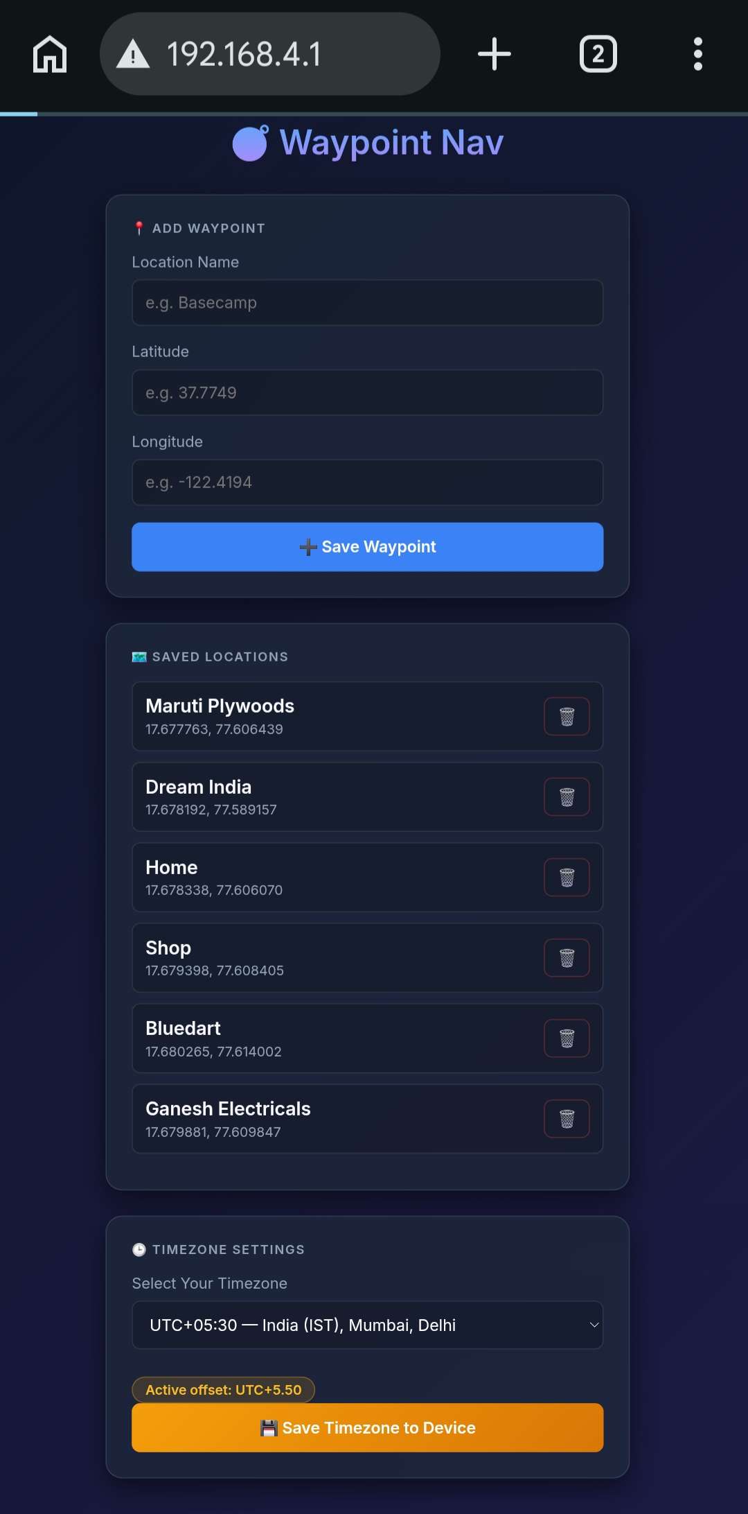
Add Waypoints:
Using the web interface, enter the details for each location you want to save:
- Location Name
- Latitude
- Longitude
Click Save to store the waypoint.
You can add multiple locations that will later be available directly on the Pathfinder.
Set Your Time Zone:
The web interface also provides a time zone selection menu.
Simply:
- Select your local time zone.
- Click Save.
This ensures the device displays the correct local time.
Persistent Storage:
All waypoint and time zone information is stored in the ESP32's Non-Volatile Storage (NVS).
This means your settings remain saved even after the device is powered off.
Once saved, the locations are automatically loaded and become available within the Pathfinder menu system.
Calibrate the Compass:
Before using Pathfinder for navigation, the compass must be calibrated.
Start Calibration
- Double-click the encoder knob to open the menu.
- Scroll using the rotary encoder.
- Select Settings.
- Open Calibrate Compass.
The calibration process will guide you through eight compass directions:
- North (N)
- North-East (NE)
- East (E)
- South-East (SE)
- South (S)
- South-West (SW)
- West (W)
- North-West (NW)
For each direction:
- Physically face the indicated direction.
- Press the encoder knob to record the measurement.
- Move to the next direction and repeat.
This is typically a one-time setup unless the device is moved to a new environment or the compass performance changes.
Troubleshooting:
If you notice that the navigation arrow is not pointing accurately toward the destination:
- Repeat the compass calibration process.
- Ensure you are facing the correct direction during each calibration step.
- Keep the device away from large metal objects or strong magnetic fields while calibrating.
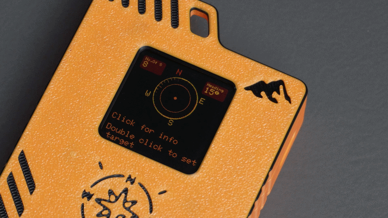
Start Navigating:
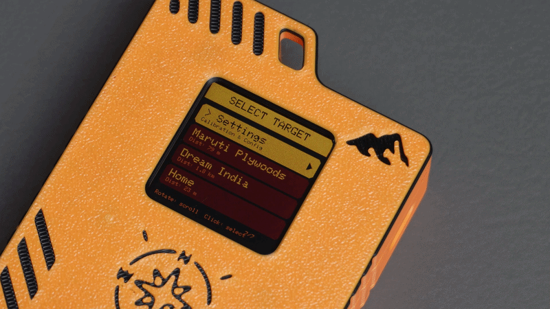
Once your locations have been added and the compass has been calibrated:
- Double-click the encoder knob to open the menu.
- Select a saved location.
The main screen will now display:
- Distance to the selected destination
- Direction arrow pointing toward the target
- Additional navigation information
As you move, the distance updates in real time while the compass continuously keeps the navigation arrow pointed toward your selected waypoint.
Step 17: How the Pathfinder Code Works
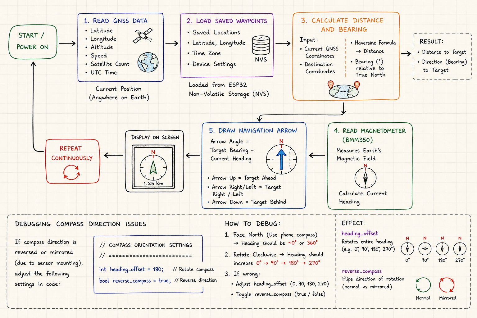
The Pathfinder firmware combines data from the GNSS receiver and the BMM350 magnetometer to create a real-time waypoint navigation system.
At a high level, the firmware performs five main tasks:
1. Read GNSS Data
The GNSS module continuously provides:
- Latitude
- Longitude
- Altitude
- Speed
- Satellite count
- UTC Time
This information is used to determine the device's current position anywhere on Earth.
2. Load Saved Waypoints
When the device starts, it loads all saved waypoints and settings from the ESP32's Non-Volatile Storage (NVS).
These include:
- Saved locations
- Latitude and longitude values
- Selected time zone
- Device settings
Because the data is stored in NVS, it remains available even after the device is powered off.
3. Calculate Distance and Bearing
Once a waypoint is selected, the firmware compares:
- Current GNSS coordinates
- Destination coordinates
Using the Haversine Formula, it calculates the shortest distance between the two points on the Earth's surface.
The code also calculates the bearing, which represents the direction of the destination relative to true north.
The result is:
- Distance to target
- Direction of target
4. Read the Magnetometer
The BMM350 continuously measures the Earth's magnetic field.
Using these readings, the firmware calculates the device's current heading.
Unlike GNSS heading, the compass continues to work even when the user is standing still.
This allows Pathfinder to always know which direction it is facing.
5. Draw the Navigation Arrow
The final navigation arrow is calculated using:
Arrow Angle = Target Bearing - Current HeadingIf the destination is directly ahead, the arrow points straight up.
If the destination is to the left or right, the arrow rotates accordingly.
This process repeats continuously, providing real-time navigation guidance.
Debugging Compass Direction Issues
Depending on how the magnetometer is mounted inside the enclosure, the compass direction may not match the expected orientation.
Common symptoms include:
- Arrow points in the opposite direction
- Arrow appears mirrored
- North and South are swapped
- East and West are reversed
To correct this, Pathfinder includes two compass configuration settings:
// ==========================================
// COMPASS ORIENTATION SETTINGS
// ==========================================
int heading_offset = 180;
bool reverse_compass = true;
heading_offset: This value rotates the entire compass heading.
Example:
int heading_offset = 0;No rotation applied.
int heading_offset = 90;Compass rotates by 90 degrees.
int heading_offset = 180;Compass rotates by 180 degrees.
If your compass consistently points in the wrong direction by a fixed amount, adjust this value.
Typical values:
- 0°
- 90°
- 180°
- 270°
reverse_compass: This setting reverses the compass rotation direction.
bool reverse_compass = false;Normal operation.
bool reverse_compass = true;Reverse heading calculation.
Use this if:
- Turning left causes the arrow to move right.
- Turning right causes the arrow to move left.
- Compass behavior appears mirrored.
Quick Debug Procedure
After uploading the firmware:
Test 1: Face North
Use your phone's compass and face north.
The Pathfinder heading should display approximately: 0° or 360°
Test 2: Rotate Clockwise
Turn slowly clockwise.
The heading should increase smoothly:
0° → 90° → 180° → 270°If the values decrease instead, try:
reverse_compass = !reverse_compass;
Test 3: Check Orientation
If North appears as South:
heading_offset = 180;If North appears as East:
heading_offset = 90;If North appears as West:
heading_offset = 270;
These two settings allow the firmware to compensate for different magnetometer mounting orientations without requiring any hardware changes.
Conclusion

Building Pathfinder was a fascinating journey that combined embedded electronics, GNSS positioning, digital compasses, wireless configuration, firmware development, 3D design, and product prototyping into a single project.
What started as a simple question "Can I build a device that continuously shows the distance and direction to a destination?" eventually became a fully functional handheld waypoint navigator capable of guiding users to predefined locations in real time.
What fascinated me most about this project was discovering that the concept itself is not new. While building it, I learned that waypoint navigators and similar navigation aids existed decades before smartphones and Google Maps became part of our daily lives.
It made me appreciate the engineers and inventors of that era. They achieved incredible things with limited tools, limited computing power, and without the software ecosystems, development frameworks, AI assistants, and resources that we have today.
With modern hardware, open-source libraries, and a bit of coding, I was able to recreate a similar system in just a couple of days. That realization reminded me that innovation doesn't always mean inventing something completely new. Sometimes the best ideas come from revisiting old concepts and rebuilding them with modern technology.
Along the way, I learned more about GNSS systems, navigation mathematics, magnetometer calibration, embedded user interfaces, and the practical challenges of turning a prototype into a portable device.
My biggest takeaway from this project is simple:
Think like the pioneers of the past, but build with the tools of today.
I hope this project inspires you to explore navigation technology, learn something new, and perhaps build your own version of Pathfinder. If you do, I'd love to see what improvements and ideas you add to it.
Happy building!