This project shows how to build a desk fan powered by a 12V power tool battery and controlled by an old IR remote. Despite using a PIC18F45K50 whose UART can handle at most 9-bit signals, it was programmed to receive 10-bit numbers by using the framing error to detect the last bit. A Buck boost converter from AliExpress buck converter board to get the 5V used to power the pic.
Warning, the 3D model used for the battery holder has the markings for the polarity inverted, the terminal marked as +ve is actually -ve and vice versa.
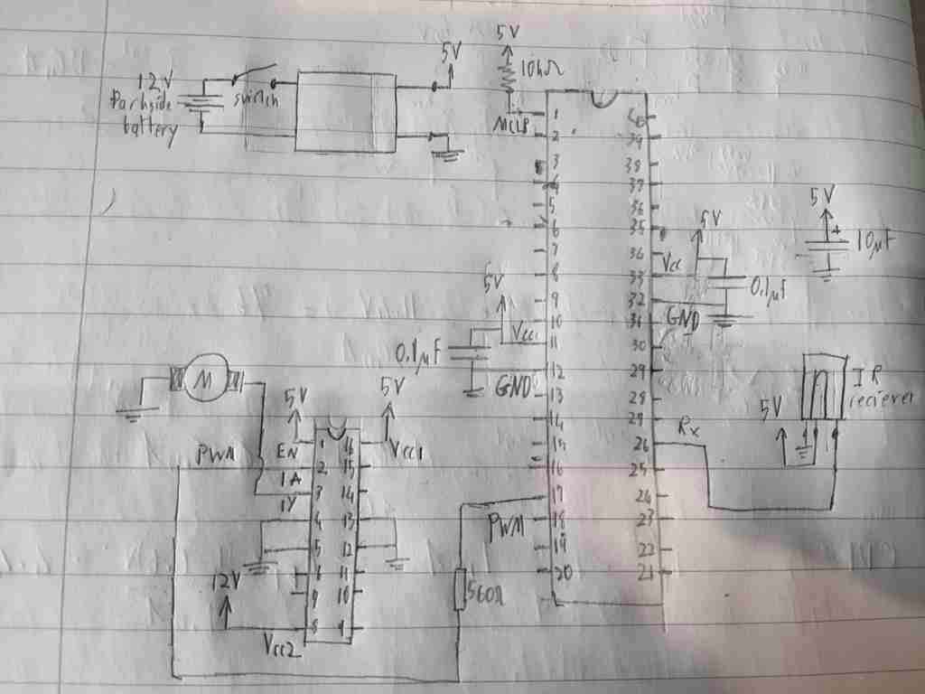
Circuit diagram
How IR Remote Work
.png)
IR remotes send serial commands using a 38kHz of carrier frequency. The IR receiver is designed to filter out other signals. Fore more on information check: https://www.electronicwings.com/sensors-modules/ir-communication, this article helped me learn how to use IR receivers. If I recall my specific receiver is the TSOP1730, however the one shown in this link should also work.
side note: if you design your own emitter, make sure that the signal on the emitter's LED is inverted (signal is low when there is no data).
Receiving 10-bit with a 9-bit UART
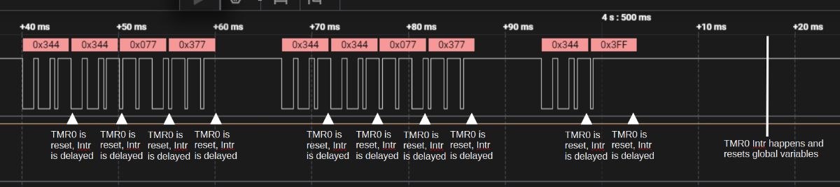
The remote I used was one lying about in house, to identify the codes sent by this remote, I attached the output of the IR receiver to a logic analyser, this revealed that the remote sends codes consistent of 4 10-bit numbers with bound rate of 2400.
This presents a problem since the PIC18F45K50 can receive a maximum of 9-bit numbers. While testing with my logic analyzer, I noticed that when set to analyze 9-bit serial signals, the logic analyzer software gave a framing error on the 10th bit when it was 0 and no error when the 10th bit was 1:
.png)
The micro-controller can also detect framing error, in my code the first 9-bits are detected normally and the last bit is detected using the framing error flag.
Motor Driver Circuit
To convert the 5V PWM of the pic to a 12V PWM signal for the DC motor a L293D chip is used:
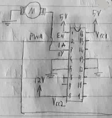
The L293D chip uses interna diodes (unlike the L293), hence external fly-back diodes are not needed to protect the motor (remember DC motors have some inductance which causes high-voltage spikes when motor is turned off). Side note, the chip can operate 4 motors or 2 in an H-ridge configuration.
Pin 8 (Vcc2) is connected to the high-side voltage and pin 16 (Vcc1) is connected to the low-side voltage.
Pins 4, 5, 12, and 13 are GND (and heat-sink pins when larger loads are attached).
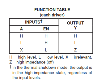
The enable (EN) pin(s) sets the corresponding output pin to high impedance as indicated by the table in the data sheet.
In my project the PWM duty cycle goes from 33% to 66% to 100%, and back to 33% on receiving the correct command from the remote.
Connecting the motor:
As you know DC motors have 2 pins on the back which are very difficult to solder wires onto. I ruined one motor trying to solder on to it, hence for the second I just used Crimp Cable Connectors:
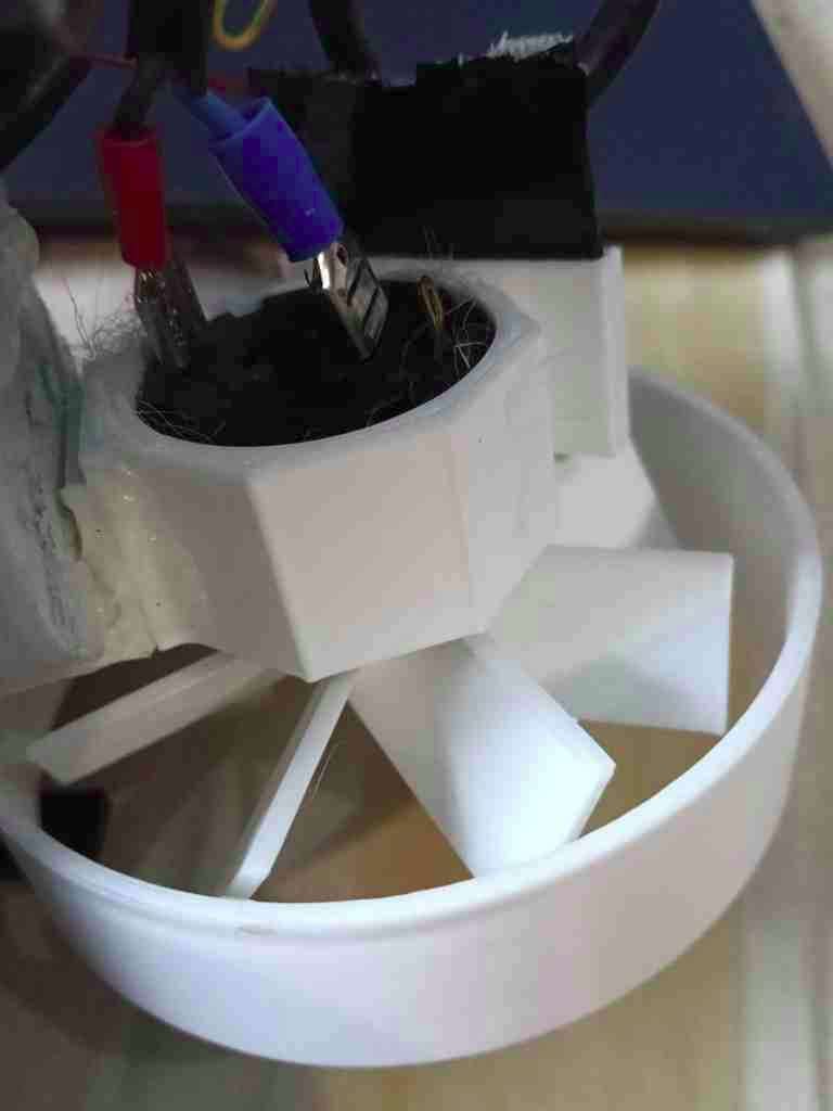
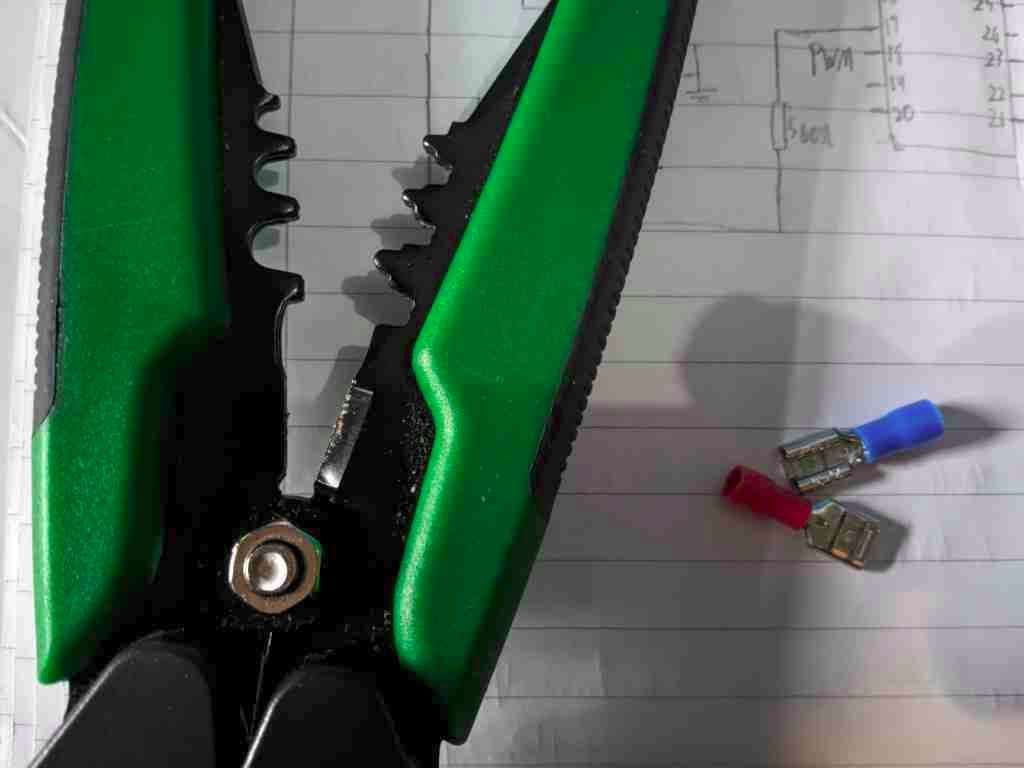
Note: I had to tighten the Crimp Cable Connectors with a pair of pliers, where they attach to the motor.
Code
The code is already heavily noted, hence I will not explain it entirely.
main()
Main calls all the configuration functions: _main_pinConfig(), _main_config_TMR0(), config_Intr()... etc, before entering an infinite wile loop.
processing codes
As already mentioned, the IR remote sends a 4 number codes and keeps repeating it as long as the buttons is held. The pic has to keep track of which number it is on and to keep track when the code is repeated because the user is still holding one of the buttons.
To achieve these 2 objectives, the global variable i is used to keep track of which number is received (1st 2nd,... or 4th) and the variable newMessage is set to 0 when a complete 4 number code is received, no new codes are processed until newMessage is set back to 1.
i and newMessage are cleared periodically by timer 0's interrupt. i has to be cleared in case one of the 4 numbers is missed, which would cause errors. newMessage, as mentioned, prevents the code from receiving new codes, TMR0 is reset every time the UART receives something, the timer is set such that the time between interrupts (hence resetting newMessag) is longer than the time taken for the IR remote to resend the code when a button is held...
This prevents the pic from acting on repeated codes until the user lets go of the button...
Note: the number's received are stored in array xx this doesn't have to be cleared since i is used as an index pointing to where they are stored. if statements in the Rx Intr are used to check the code and set the PWM accordingly.
Interrupts
Intr are configured and enabled by the config_Intr()function called by main(). TMR0 's Intr is configured as a low priority and Rx is configured as high priority. When I configured the Intrs this way I was still figuring out how I would structure the code... the code disables Intr when it enters either the high or the low Intr Service Routine, that means that the high priority Intr can't run anyway while the low priority Intr is running. An if statement could have been used instead to check the Intr flags instead, but I kept the separate Intr Service Routines for the 2 peripherals.
In MPLAB the Intr Service Routine for the low and high priority Intr are:
void __interrupt(low_priority) isrLi(void) {}; and
void __interrupt(high_priority) isrHi(void) {};
respectively.
PWM
the PWM o/p is provided by a capture compare module, which is driven by TMR2, in this code CCP1 is used. Meaning that when a the counter reaches a certain value it toggles the PWM output. TMR2's counter register is compared with the value of the PR2 register (for frequency) and the CCPR1L register ( for duty cycle).
To calculate the value of PR2 an equation is derived from equation 15-1 from the data sheet:
.png)
Tosc = 1/Fosc (system clk frequency). Since I am using the __delay_ms(), I have _XTAL_FREQ = to Fosc.
.png)
The desired frequency is 32000Hz => PWM period = 1/32000
Presacral is set to 4.
The final equation, in theory, should be: PR2 = (char)((_XTAL_FREQ/(32000*4*4)) - 1)
(char) is used since PR2is an 8-bit register, (char) converts the equations result to an 8-bit value.
However I kept having a weird error, the equation should return 15 instead it kept returning 0x73... After some trial and error and consulting ChatGPT I found that the problem is in the compiler using 16-bit signed int arithmetic (common on PIC compilers), the max values for 16-bit signed is 32767... To force the compiler to use floating point, you can use decimal numbers or the type cast (float):
PR2 = (char)(((float)_XTAL_FREQ)/((32000.0*4.0*4.0))) - 1;
As already mentioned the PWM's duty cycle goes from 33% to 66% to 100%, and back to 33%.
Tx_9bits and pin RC0
during testing pin RC0 was used to indicate when certain parts of the code run, this was done by toggling the pin's output at certain parts of the code.
The UART was also used during debugging, if you use this, remember to un-note the corresponding lines of code in _main_pinConfig()and USART_Init_9bit() and un-note the function UART_Tx_9bit(). I like to make sure Tx Intr is disabled in config_Intr().
void UART_Tx_9bit(unsigned int data) {
    while (!TXIF);              // Wait until TXIF is set (buffer is empty)

    TX9D = (data >> 8) & 1;     // Set 9th bit (bit 8 of data)
    TXREG = data & 0xFF;        // Load lower 8 bits into TXREG
}
3D print
Unfortunately the actual; 3D printed structure is not as refined. The parts that hold the circuit boards are an afterthought, the IR receiver still requires a mount, I do not know how to best design fan-blades, however it still better than the first one I found on the internet.
For the battery holder/adapter, I found one on the Thingiverse but lost the original file. However, I believe I found the model again.
Warning, the 3D model used for the battery has the markings for the battery polarity inverted, the terminal marked as +ve is actually -ve and vice versa, this appears to also be the case for the new one.
.png)
Code
// CONFIG1H
#pragma config FOSC = INTOSCIO  // Oscillator Selection (Internal oscillator)
// CONFIG2H
#pragma config WDTEN = OFF      // Watchdog Timer Enable bits (WDT disabled in hardware (SWDTEN ignored))
// CONFIG3H
#pragma config PBADEN = OFF     // PORTB A/D Enable bit (PORTB<5:0> pins are configured as digital I/O on Reset)
#pragma config LVP = OFF // Single-Supply ICSP Enable bit (SingleSupply ICSP disabled)

#define _XTAL_FREQ 8000000 // used for __delay_ms() function

#include <xc.h>


void delay_ms500(void){
    __delay_ms(500);// this method lets you include a softeware delay once in your code only
};

void _main_pinConfig(void){
	// set pins as digital
    ANSELA=0;
    ANSELB=0;
    ANSELC=0;
    ANSELD=0;
    TRISCbits.TRISC2 = 0;		// Set CCP1 pin as output for PWM out

    // TRISCbits.TRISC6=0;		// Make Tx (transmit) pin as output (Tx was used during testing)
    TRISCbits.TRISC7=1;		// Make Rx (recieve) pin as input //not realy necisary in our case

    // pin RC0 was used during testing, I would set it to toggle on parts of the
    //  code I wanted to see if and when they were executed and read it using a logic analyser
    // TRISCbits.TRISC0=0;
    //PORTCbits.RC0=0;
};

void _main_oscillatorConfig(void){

    OSCCONbits.IRCF=6;//8Mhz internal
    OSCCONbits.HFIOFS=1;//HFINTOSC frequency stable
    OSCCONbits.SCS=2;// internal oscillator

};

void _main_config_TMR0(void){
    T0CONbits.TMR0ON = 0; // TMR off for now
    T0CONbits.T08BIT = 0; // = 0 => TMR is set as 16-bit
    T0CONbits.T0CS = 0; // = 0 => Internal instruction cycle clock (FOSC/4)
    T0CONbits.PSA = 0; // = 0 => prescalar is used
    // T0CONbits.T0PS = 0b001; // = 0b001 => = 1:4 prescale value
    T0CONbits.T0PS = 0b000; // = 0b000 => = 1:2 prescale value
};

void config_Intr(void){
	PIE1bits.TMR2IE = 0; // TMR 2 (PWM) Intr is off

	// for TMR0
    INTCONbits.TMR0IF = 0; // make sure Intr flag is cleared
    INTCON2bits.TMR0IP = 0; // low priority
    INTCONbits.TMR0IE = 1; // = 1 enable TMR0 Intr

	// for Rx (UART)
    PIR1bits.RCIF = 0; // make sure Intr flag is cleared
    IPR1bits.RCIP = 1; // high priority
    PIE1bits.RCIE = 1; // = 1 => enable Rx Intr

    // PIE1bits.TXIE=0;

    RCONbits.IPEN = 1;// =1 => enable priority levels

    INTCONbits.PEIE = 1; // =1 => Enables all low priority interrupts
    INTCONbits.GIE = 1; // =1 => Global Interrupt Enable bit
};

char CCP_register_val[3]; // ths variable will store values related to the PWM duty cycle
uint8_t PWM_step = 0; // step 0 => duty cycle 33%, 1 => 67%, 2 => 100%

// the PWM o/p is provided by a capture compare module, which is driven by TMR2, in this code CCP1 is used
//
// oversimplified diagram;    +----------------------------------------------------------------+
//       +--------------+     | comparator:                                                    |
//       | TMR2 counter | --> |    compare TMR2 counter registor with that of the PR2 register |
//       +--------------+     |    (frequency) and the CCPR1L register (duty cycle)            |
//          (Register)        +----------------------------------------------------------------+
//

void config_TMR2_and_PWM(void){


    T2CONbits.TMR2ON = 0; //timer is off for now
    T2CONbits.T2OUTPS = 0; //postscaler is 1:1
    T2CONbits.T2CKPS = 1; //prescaler set to 4


    PR2 = (char)(((float)_XTAL_FREQ)/((32000.0*4.0*4.0))) - 1; // set PWM frequency using equation derived from equation 15-1 in data sheet

	// calculate the values that should be loaded to CCPR1L to provide the desired duty cycles
    CCP_register_val[0] = (char)((PR2+1)*33/100); // 33%
    CCP_register_val[1] = (char)((PR2+1)*67/100); // 67%
    CCP_register_val[2] = (char)(PR2+1);          // 100%

    CCPR1L = CCP_register_val[PWM_step];	//load duty cycle value

    CCP1CON = 0x0C;	// Set PWM mode and no decimal for PWM
    TMR2 = 0;		// Clear Timer2 initially
};

void USART_Init_9bit(int baud_rate){

    float rate;

    PIE1bits.RCIE=0; // disable Reciev Intr
    PIE1bits.TXIE=0; // disable transmit Intr    PIE1bits.RCIE=0; // disable Reciev Intr
    PIE1bits.TXIE=0; // disable transmit Intr


    RCSTA1bits.ADDEN = 0; //Address Detect Enable bit (9-bit mode) 0 = Disables address detection
    RCSTA1bits.RX9 = 1; //9-bit Receive Enable bit, 1 = Selects 9-bit reception

    rate=(((float) (_XTAL_FREQ)) / (64*((float) baud_rate))) - 1;  //finding bound rate (rate of transmition))
    // RX9D: Ninth bit of Received Data
    // This can be address/data bit or a parity bit and must be calculated by user firmware

    SPBRG = (int)rate;	// Baud rate=9600 SPBRG=(F_CPU /(64*9600))-1
    BRGH = 0;            // Low-speed
    BRG16 = 0;           // 8-bit baud rate generator

    TXSTAbits.TX9 = 1;   // Enable 9-bit transmission
    RCSTAbits.RX9 = 1;   // Enable 9-bit reception

    // TXEN = 1;            // Enable transmitter
    SPEN = 1;            // Enable serial port (TX/ RX enabled)
    CREN = 1;            // Enable continuous reception
    return;
}

/*
void UART_Tx_9bit(unsigned int data) {
    while (!TXIF);              // Wait until TXIF is set (buffer is empty)

    TX9D = (data >> 8) & 1;     // Set 9th bit (bit 8 of data)
    TXREG = data & 0xFF;        // Load lower 8 bits into TXREG
}*/

// codes for my remote:

//	2400Hz
//    buttins       codes
//		O   0X344 0X344 0X377 0X077		on/off button
//		-   0X344 0X344 0X377 0X347		fan speed button
//		-   0X344 0X344 0X077 0X377		not used in this code


uint8_t i=0; // Each command on my remote sends 4 numbers, this counts which number was recieved

unsigned int data, flag=0; // used when processing data recieved from Uart
unsigned int xx[4]; // stores the recieved code
int newMessage = 1; // since remote keeps transmitting aslong as button is held, this marks if it is the first time remote transmits or if it is a repeated transmission

// TMR 0 Intr. Ensure clearing setain variables every so often in case of errors.. etc
void __interrupt(low_priority) isrLi(void) {
    INTCONbits.GIE = 0; // temporally disable all Intr

    INTCONbits.TMR0IF = 0; // clear flag
    i = 0;
    newMessage = 1;

    // PORTCbits.RC0 = PORTCbits.RC0^1; // was used during testing

    INTCONbits.GIE = 1; // enable Intr
};

// Rx Intr
void __interrupt(high_priority) isrHi(void) {
    INTCONbits.GIE = 0; // temporally disable Intr

    // Rx flag clears automatically by hardware

	// teporary turn off TMR0 and reset TMR0 counter
    T0CONbits.TMR0ON = 0;
    TMR0L = 0;
    TMR0H = 0;

	// check for framing error, if recieved set the variable flag
    if (RCSTA1bits.FERR == 1) {
        flag = 1;
    }

	// store the recived data
    data = (RX9D << 8);         // Read 9th bit and shift into bit 8
    data |= RCREG;              // Read lower 8 bits from RCREG

	// if this is the first time the remote sent continue processing
    if (newMessage == 1){
        if (flag == 1) {
            // framing error detected => 10th bit is 0
            xx[i] =  data;
        }else{
			// no framing error => 10th bit is 1
            xx[i] =  data | 0x200;
        }
        flag = 0; // clear flag

        i++; // remote sends 4 number codes, i counts which one it is on

		// when 4th number is recieved
        if(i>=4){
            i = 0;
            // UART_Tx_9bit(0); // Tx was used during testing
            if (xx[0] == 0x344 && xx[1] == 0x344){
                if (xx[2] == 0x377 && xx[3] == 0x077){// on/off
                    // UART_Tx_9bit(1); // Tx was used during testing
                    if (T2CONbits.TMR2ON == 1){// if TMR2 is off it's time to turn PWM off
                        CCP1CON = 0x0;
                        T2CONbits.TMR2ON = 0;
                        TRISCbits.TRISC2 = 0;   // Set CCP2 pin as output
                        LATCbits.LATC2 = 0;     // Force low
                    }else{// turn PWM on
                        CCP1CON = 0x0C;
                        T2CONbits.TMR2ON = 1;
                    }

                    newMessage = 0; // note it seems that some cleaning is still necessary, but I’m already nearly finished writing this articl and don't want to break the code by accident...
                }else if (xx[2] == 0x377 && xx[3] == 0x347){// increment PWM duty cycle
                    // UART_Tx_9bit(2); // Tx was used during testing
                    PWM_step++;
                    if (PWM_step >= 3){
                        PWM_step = 0;
                    }
                    CCPR1L = CCP_register_val[PWM_step];
                    newMessage = 0;
                }else if (xx[2] == 0x077 && xx[3] == 0x377){// not used
                    // UART_Tx_9bit(3); // Tx was used during testing
                    newMessage = 0;
                }
            }
        }
    }

    T0CONbits.TMR0ON = 1;// restart TMR0

    INTCONbits.GIE = 1; // enable Intr
};

void main(void) {

    // config oscillator
    _main_oscillatorConfig();

    // start Uart
    USART_Init_9bit(2400);
    delay_ms500();

    _main_pinConfig();

    _main_config_TMR0();

    config_Intr();

    config_TMR2_and_PWM();

    // turn timers on
    T2CONbits.TMR2ON = 1;	// TMR2 is used for PWM
    T0CONbits.TMR0ON = 1;

    while(1);

    return;
}

/*
2400
O   0X344 0X344 0X377 0X077
-   0X344 0X344 0X377 0X347
-   0X344 0X344 0X077 0X377
 */

/*
              _______
        MCLR-|1    40|-VB7
        RA0 -|2    39|-RB6
        RA1 -|3	   38|-RB5
        RA2 -|4	   37|-RB4
        RA3 -|5	   36|-RB3
        RA4 -|6	   35|-RB2
        RA5 -|7	   34|-RB1
        RE0 -|8	   33|-RB0
        RE1 -|9	   32|-VDD
        RE2 -|10   31|-VSS
        VDD -|11   30|-RD7
        VSS -|12   29|-RD6
        RA7 -|13   28|-RD5
        RA6 -|14   27|-RD4
        RC0 -|15   26|-RC7 -Rx
        RC1 -|16   25|-RC6- TX
  PWM - RC2 -|17   24|-D+
        VUSB-|18   23|-D-
        RD0 -|19   22|-RD3
        RD1 -|20   21|-RD2
             |_______|*/