
ADXL345 is an IC specifically designed for measuring tilt angles. Although it does not have the same rotation angle measurement function as MPU6050, its accuracy is very high (16 bits), and it can measure angle changes below 1 °. It is also easy to use because it uses the same library as OLED and can be read with a simple driver.
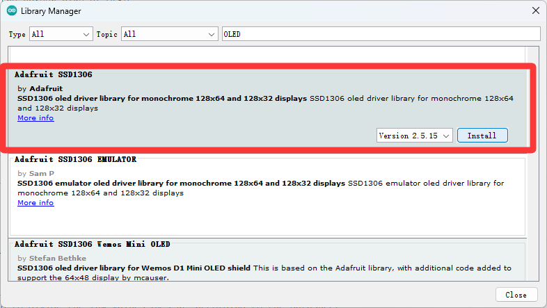
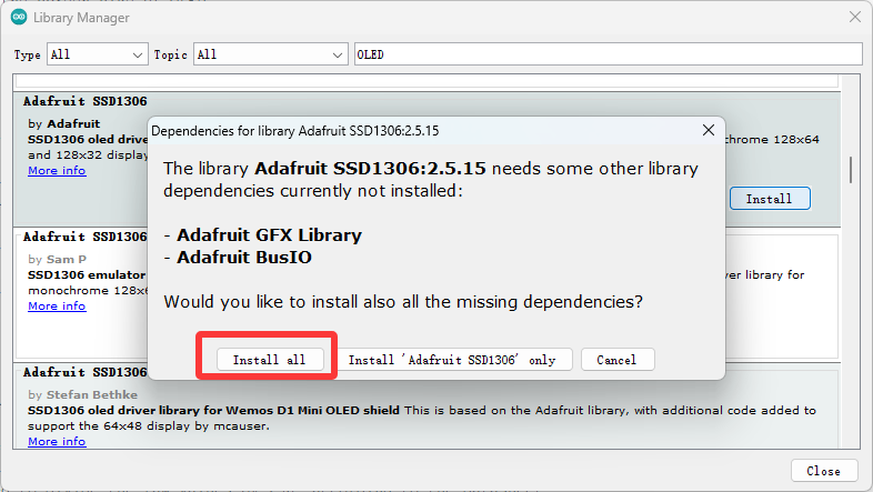
After installing the library, we can start writing code (in fact, we just need to copy it)
#include <Wire.h> // Wire library - used for I2C communication
#include <Adafruit_GFX.h>
#include <Adafruit_SSD1306.h>//OLED library
Adafruit_SSD1306 display(128,64, &Wire, -1);//Set the screen size of OLED
int ADXL345 = 0x53; // The ADXL345 sensor I2C address
float X_out, Y_out, Z_out; // Outputs
void setup() {
Serial.begin(9600);
Wire.begin(); // Initiate the Wire library
// Set ADXL345 in measuring mode
Wire.beginTransmission(ADXL345); // Start communicating with the device
Wire.write(0x2D); // Access/ talk to POWER_CTL Register - 0x2D
// Enable measurement
Wire.write(8); // (8dec -> 0000 1000 binary) Bit D3 High for measuring enable
Wire.endTransmission();
display.begin(SSD1306_SWITCHCAPVCC, 0x3C);//Initialize OLED and set IIC communication address
delay(10);
}
void loop() {
Wire.beginTransmission(ADXL345);
Wire.write(0x32); // Start with register 0x32 (ACCEL_XOUT_H)
Wire.endTransmission(false);
Wire.requestFrom(ADXL345, 6, true); // Read 6 registers total, each axis value is stored in 2 registers
X_out = ( Wire.read()| Wire.read() << 8); // X-axis value
X_out = X_out/256; //For a range of +-2g, we need to divide the raw values by 256, according to the datasheet
Y_out = ( Wire.read()| Wire.read() << 8); // Y-axis value
Y_out = Y_out/256;
Z_out = ( Wire.read()| Wire.read() << 8); // Z-axis value
Z_out = Z_out/256;
Serial.print("Xa= ");
Serial.print(X_out);
Serial.print(" Ya= ");
Serial.print(Y_out);
Serial.print(" Za= ");
Serial.println(Z_out);
display.clearDisplay();//Clear screen
display.setTextColor(WHITE);//Setting text color, monochrome OLED is invalid, but must have
display.setTextSize(2);//Set text size
display.setCursor(0, 0);
display.print("X: ");
display.print(X_out);
display.setCursor(0, 20);
display.print("Y: ");
display.print(Y_out);
display.setCursor(0, 40);
display.print("Z: ");
display.print(Z_out);
display.display();//Execute Display
delay(100);
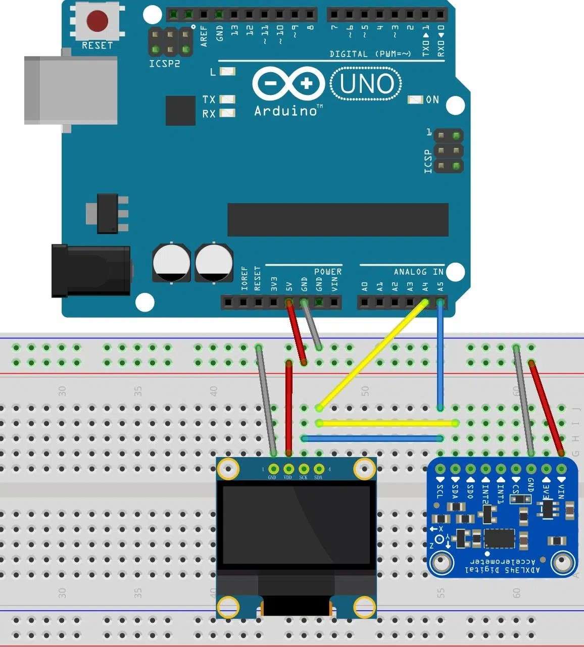
}Finally, the wiring method
Video usage on youtube: