
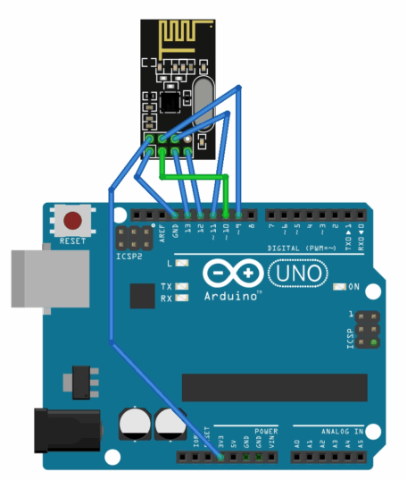
Firstly, we need to connect NRF24l01 to Arduino,like this
Next, we will burn the code into Arduino. Due to the complex code structure, we will directly provide the actual usage code here.
The communication address is very important, and the sending and receiving ends must have the same address. NRF24L01 can store the sending and receiving addresses, and their relationship is very simple. The receiving address can be seen as its own location, while the sending address is like the recipient address on the package. Only when the address of the package matches its own location, can it receive the package. So the reason why the sending address and receiving address must be consistent. Please note that the address of NRF24L01 is a 5-byte array.
#include <SPI.h>
#include <nRF24L01.h>
#include <RF24.h>
#define CE_PIN 9
#define CSN_PIN 10
RF24 radio(CE_PIN, CSN_PIN);
//New Device
const uint8_t TxAddress[5] ={0x00,0x00,0x00,0x00,0x00};
//Sender address
const uint8_t RxAddress[5] ={0x01,0x00,0x00,0x00,0x00};
//Receiver address
char receivedData[32];
//Only one sender and one receiver can transmit up to 32 char arrays
void setup() {
Serial.begin(9600);
while (!radio.begin()) {
Serial.println("NRF24L01 initialization failed!");
delay(100);
}
//radio.setChannel(0);
//Set Communication channel 0-126
//radio.setDataRate(RF24_1MBPS);
//Set the air transmission rate to 250Kbps,1Mbps,2Mbps.
radio.openReadingPipe(0,RxAddress);
//The receiving end setting can be omitted as the sending end.
//Set data channel 0-5, set the receiving end (own) address
radio.openWritingPipe(TxAddress);
//The sender setting can be omitted as the receiver. Set the recipient's address
//radio.setPALevel(RF24_PA_MIN);
//Adjust the transmission power(RF24_PA_MIN、RF24_PA_LOW、RF24_PA_HIGH、RF24_PA_MAX)
//radio.setCRCLength(RF24_CRC_8);
//Modify CRC length(RF24_CRC_DISABLED、RF24_CRC_8、RF24_CRC_16)
radio.stopListening();
//Set as sender
radio.write("hello",5);
//send data and data length
radio.startListening();
//Set as receiving end
Serial.println("NRF24L01 Started, waiting for data..");
Serial.println("-----------------------------------");
}
void loop() {
if (radio.available()) {
//If there is data available
radio.read(&receivedData, sizeof(receivedData));
//read data
Serial.println("new data!");
Serial.print("data1:");
Serial.println(receivedData[0]);
Serial.print("data2:");
Serial.println(receivedData[1]);
Serial.print("data3:");
Serial.println(receivedData[2]);
//...
//Reply to the sender, you don't need to
//delay(10);
//radio.stopListening();
//radio.write("OK",2);
//radio.startListening();
}
delay(10);
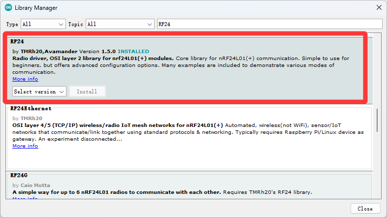
}Note that we need to download this library to run the code properly
Burn the modified address code separately to two Arduino devices to use. If you are unsure how to write the address, you can change all addresses to 0x00.
Actual effect: