
Overview
Women's personal safety and emergency health monitoring remain significant challenges, particularly in situations where immediate manual intervention is not possible. Conventional safety solutions such as panic buttons, mobile SOS applications, and emergency alert systems depend heavily on user interaction, making them ineffective during sudden falls, medical emergencies, unconsciousness, or high-stress situations.
To address this limitation, this project presents a Smart Women Safety Wearable Device based on IoT and embedded system technologies. The wearable continuously monitors the user's physiological and motion-related parameters using integrated sensors, enabling real-time detection of abnormal heart rate conditions and fall events without requiring any manual activation.
The system is built around an ESP32 microcontroller, MPU6050 motion sensor, and MAX30102 heart-rate sensor. Sensor data is processed locally using threshold-based detection algorithms to identify potential emergency situations. Upon confirmation of a critical event, the device initiates a 10-second verification window to minimize false alarms. If no cancellation is received, the system automatically transmits an emergency alert to a mobile application.
The mobile application immediately initiates automated phone calls to two predefined emergency contacts and subsequently sends emergency notification messages along with the user's location information. This fully automated workflow ensures rapid communication and assistance even when the user is unable to operate a smartphone or manually request help.
The proposed solution combines wearable sensing, real-time health monitoring, wireless communication, and automated emergency response into a compact and low-power system designed to improve personal safety and emergency accessibility.
Problem Statement
Personal safety systems currently available in the market primarily rely on manual activation through panic buttons, mobile applications, or wearable triggers. While effective in some situations, these approaches become unreliable when the user is physically incapacitated, unconscious, injured, or unable to access the triggering mechanism during an emergency.
Similarly, many low-cost wearable devices focus on a single functionality such as location tracking or emergency notification, without integrating real-time health monitoring and automatic emergency detection. As a result, critical events such as severe falls, abnormal heart-rate conditions, or sudden medical emergencies may go unnoticed until external assistance becomes available.
The key challenge is to develop an affordable, wearable, and autonomous safety system capable of continuously monitoring both physiological and motion-related parameters, accurately detecting emergency situations, and automatically initiating emergency communication without requiring user intervention.
This project addresses these challenges by integrating fall detection, heart-rate monitoring, smartphone connectivity, automated calling, emergency messaging, and location sharing into a single low-cost wearable platform.
Proposed Solution
To overcome the limitations of conventional safety devices, a fully automated wearable safety system was developed that continuously monitors both physiological and motion-related parameters and responds to emergencies without requiring manual intervention.
The proposed solution consists of a compact wrist-worn device built around the ESP32 microcontroller. The device integrates an MPU6050 inertial measurement unit (IMU) for motion analysis and a MAX30102 sensor for continuous heart-rate monitoring. These sensors operate continuously and provide real-time data to the ESP32 for processing.
Three independent emergency detection mechanisms are implemented:
- Fall Detection
- Heart Rate Anomaly Detection
- Panic Movement Detection
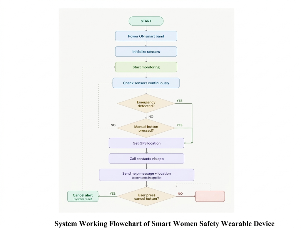
Whenever any of these detection algorithms identifies a potential emergency, the system enters a 10-second verification window. During this period, the user can cancel the alert if it was triggered accidentally. If no cancellation is received, the device automatically generates an emergency alert.
The ESP32 transmits the alert information to Google Firebase Realtime Database through Wi-Fi. A companion Flutter mobile application continuously monitors the database for incoming alerts. Upon receiving an emergency notification, the application automatically retrieves the user's GPS location, generates a Google Maps location link, initiates phone calls to predefined emergency contacts, and sends SMS notifications containing the alert details and live location.
The complete solution combines wearable sensing, embedded intelligence, cloud communication, smartphone integration, and automated emergency response into a single low-cost safety platform capable of operating without user interaction during critical situations.
System Architecture
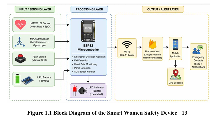
The Smart Women Safety Wearable Device is organized into four major functional layers: the Sensing Layer, Processing Layer, Cloud Communication Layer, and Emergency Response Layer. This layered architecture enables continuous monitoring, intelligent decision-making, reliable communication, and rapid emergency response.
1. Sensing Layer
The sensing layer is responsible for collecting real-time physiological and motion-related data from the user.
MAX30102 Sensor
The MAX30102 optical sensor continuously measures the user's heart rate and blood oxygen saturation (SpO₂). The sensor uses photoplethysmography (PPG) technology to detect blood volume changes and generate physiological data.
MPU6050 Sensor
The MPU6050 is a six-axis inertial measurement unit containing a three-axis accelerometer and a three-axis gyroscope. It continuously monitors body movement, acceleration, orientation, and sudden impacts, enabling reliable fall and panic movement detection.
SOS and Cancel Buttons
A manual SOS button allows the user to trigger an emergency alert voluntarily, while a cancel button is provided to dismiss accidental alerts during the verification period.
2. Processing Layer
The processing layer is implemented using the ESP32 microcontroller, which serves as the central processing unit of the wearable device.
The ESP32 continuously acquires sensor data through the I²C communication bus and executes three independent emergency detection algorithms:
- Fall Detection Algorithm
- Heart Rate Anomaly Detection Algorithm
- Panic Movement Detection Algorithm
The controller evaluates sensor readings in real time and determines whether an emergency condition exists. If an emergency is confirmed, the ESP32 generates an alert packet containing event information and prepares it for transmission.
3. Cloud Communication Layer
The cloud communication layer provides reliable data exchange between the wearable device and the smartphone application.
Google Firebase Realtime Database is used as the communication bridge. Whenever an emergency event is detected, the ESP32 uploads the following information:
- Alert Type
- Device Identifier
- Timestamp
- Heart Rate Value
- Event Status
Firebase ensures real-time synchronization and enables immediate alert delivery to the mobile application
4. Emergency Response Layer
The emergency response layer is implemented through a Flutter-based Android application.
The application continuously monitors Firebase for incoming alerts. When an emergency notification is received, the application performs the following actions automatically:
- Retrieves the user's current GPS location.
- Generates a Google Maps location link.
- Initiates a phone call to Emergency Contact 1.
- Initiates a phone call to Emergency Contact 2.
- Sends emergency SMS messages containing alert details and location information.
This fully automated workflow ensures that emergency contacts receive immediate notification even when the user is unable to interact with the device.
Overall Data Flow
The complete system workflow can be summarized as follows:
MAX30102 + MPU6050 → ESP32 Processing → Emergency Detection → Firebase Database → Flutter Mobile Application → GPS Retrieval → Emergency Calls + SMS Alerts
This architecture provides a reliable, scalable, and low-cost platform for real-time emergency detection and response.
Hardware Components
The wearable safety device is built using a combination of sensing, processing, communication, and power management components. Each component was selected to provide reliable operation while maintaining low cost and compact size.
ESP32 Development Board
The ESP32 serves as the central controller of the system. It acquires data from all sensors, executes emergency detection algorithms, communicates with Firebase over Wi-Fi, and manages the overall system operation.
Key Features:
- Dual-core 240 MHz processor
- Integrated Wi-Fi and Bluetooth
- Low power consumption
- Multiple GPIO and I²C interfaces
MPU6050 Motion Sensor
The MPU6050 is a six-axis Inertial Measurement Unit (IMU) containing a three-axis accelerometer and three-axis gyroscope.
The sensor continuously monitors body motion and orientation, enabling the detection of falls and panic movements.
Functions:
- Acceleration measurement
- Angular velocity measurement
- Fall detection
- Motion analysis
MAX30102 Heart Rate Sensor
The MAX30102 is an optical biosensor used for continuous heart-rate and SpO₂ monitoring.
The sensor operates using photoplethysmography (PPG), where variations in blood flow are detected using infrared and red LEDs.
Functions:
- Heart-rate monitoring
- SpO₂ monitoring
- Abnormal heart-rate detection
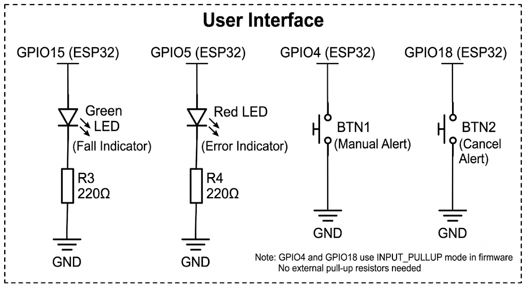
SOS and Cancel Push Buttons
Two push buttons are integrated into the system.
The SOS button allows the user to manually trigger an emergency alert, while the Cancel button allows dismissal of false alarms during the verification period.
Functions:
- Manual emergency activation
- False alarm cancellation
Status LEDs
LED indicators provide visual feedback regarding device status.
Different blinking patterns indicate normal operation, alert pending state, and emergency transmission status.
Functions:
- System status indication
- Alert notification
- Debugging assistance
LiPo Battery
A rechargeable 3.7V LiPo battery powers the complete wearable system.
The battery provides portability and enables continuous operation without external power sources.
Specifications:
- Voltage: 3.7V
- Capacity: 1500mAh
- Runtime: Approximately 8–12 hours
TP4056 Charging Module
The TP4056 module is used for battery charging and protection.
It provides overcharge, over-discharge, and short-circuit protection to ensure safe battery operation.
Functions:
- Battery charging
- Battery protection
- Power management
Component Summary
| Component | Purpose |
|---|---|
| ESP32 | Processing and Wi-Fi communication |
| MPU6050 | Fall and motion detection |
| MAX30102 | Heart-rate monitoring |
| SOS Button | Manual emergency trigger |
| Cancel Button | False alarm cancellation |
| LEDs | Status indication |
| LiPo Battery | Portable power supply |
| TP4056 | Charging and battery protection |
Detection Algorithms
The intelligence of the wearable device is implemented through three independent emergency detection algorithms running continuously on the ESP32. Each algorithm monitors a different type of emergency scenario and can independently trigger the alert sequence.
Fall Detection Algorithm
Fall detection is implemented using data from the MPU6050 accelerometer and gyroscope.
The algorithm follows a two-stage threshold-based approach:
Stage 1 – Free Fall Detection
During a fall, the resultant acceleration magnitude drops significantly due to temporary weightlessness. The system continuously calculates the acceleration vector magnitude and monitors for values below the predefined threshold.
Stage 2 – Impact Detection
Immediately after free fall, a sharp impact occurs when the body hits the ground. This produces a sudden acceleration spike exceeding the impact threshold.
A fall event is confirmed only when both conditions occur within a specified time window. This significantly reduces false detections caused by activities such as running, jumping, or rapid body movements.
Heart Rate Anomaly Detection
Heart rate data is continuously acquired from the MAX30102 sensor.
To improve reliability, a moving average filter is applied to reduce noise and motion artifacts. The filtered heart rate values are compared against predefined emergency thresholds.
An alert is generated when:
- Heart Rate < 45 BPM (Severe Bradycardia)
- Heart Rate > 140 BPM (Extreme Tachycardia)
The abnormal condition must persist for several seconds before an emergency is confirmed.
Panic Movement Detection
Panic movement detection is designed to identify sudden aggressive body movements that may occur during a struggle or physical attack.
The algorithm monitors rapid changes in acceleration and angular velocity. When multiple high-intensity motion events occur within a short duration, a panic condition is declared.
This additional detection mechanism increases user protection even when a complete fall does not occur.
Emergency Verification Logic
Whenever any detection algorithm identifies an emergency condition, the system enters a 10-second verification period.
During this period:
- Alert status is activated.
- Status LED blinks rapidly.
- User may cancel the alert.
- If no cancellation occurs, the alert is automatically transmitted.
This verification stage minimizes false alarms while ensuring genuine emergencies are reported.
Project Development Process
Step 1: Requirement Analysis
The project began with identifying the limitations of conventional women safety systems. Existing solutions were analyzed to determine common shortcomings, particularly their dependence on manual activation.
The primary design objectives were established as:
- Automatic emergency detection
- Health monitoring
- Real-time alert generation
- Location sharing
- Low-cost implementation
Step 2: System Design
A complete system architecture was designed consisting of sensing, processing, cloud communication, and emergency response layers.
Step 3: Power Supply Design
A rechargeable 3.7V LiPo battery was selected as the primary power source.
The power subsystem includes:
- LiPo Battery
- TP4056 Charging Module
- Protection Circuitry
- Voltage Regulation
The design ensures stable operation during continuous sensor monitoring and Wi-Fi communication.

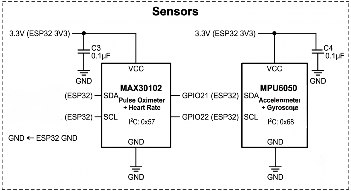
Step 4: Sensor Interfacing
The MPU6050 and MAX30102 sensors were connected to the ESP32 through the I²C communication interface.
The ESP32 continuously acquires sensor data and performs local processing before transmitting alerts.
Step 5: Firmware Development
Firmware was developed using the Arduino IDE.
Major software modules include:
- Sensor Data Acquisition
- Signal Processing
- Emergency Detection Algorithms
- Alert Management
- Firebase Communication
The software architecture was designed to support continuous real-time monitoring.
Step 6: Firebase Integration
Google Firebase Realtime Database was selected as the communication platform between the wearable device and the mobile application.
When an emergency occurs, the ESP32 uploads:
- Alert Type
- Device ID
- Timestamp
- Heart Rate Information
- Alert Status
This enables real-time synchronization between the wearable and mobile application.
Step 7: Mobile Application Development
A Flutter-based Android application was developed to receive alerts and perform emergency response actions.
The application continuously monitors Firebase and automatically responds when an alert is received.
Features include:
- Emergency Contact Management
- GPS Location Retrieval
- Automatic Calling
- Automatic SMS Transmission
- Emergency Helpline Access
Step 8: Prototype Assembly
The system was initially assembled on a breadboard for testing and debugging.
After successful validation, all components were integrated onto a compact hardware platform suitable for wearable deployment.
Proper cable management, power distribution, and sensor placement were implemented to improve reliability.
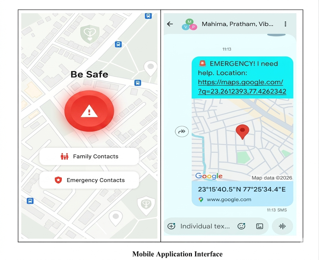
Mobile Application
The companion mobile application serves as the emergency response interface for the wearable device.
The application continuously monitors Firebase for incoming alerts generated by the wearable system.
When an emergency alert is received, the application automatically performs the following actions:
- Retrieves the user's current GPS location.
- Generates a Google Maps location link.
- Calls Emergency Contact 1.
- Calls Emergency Contact 2.
- Sends emergency SMS notifications.
- Stores alert information for future reference.
Additional features include:
- Contact Management
- Emergency Helpline Access
- Alert History
- Location Sharing
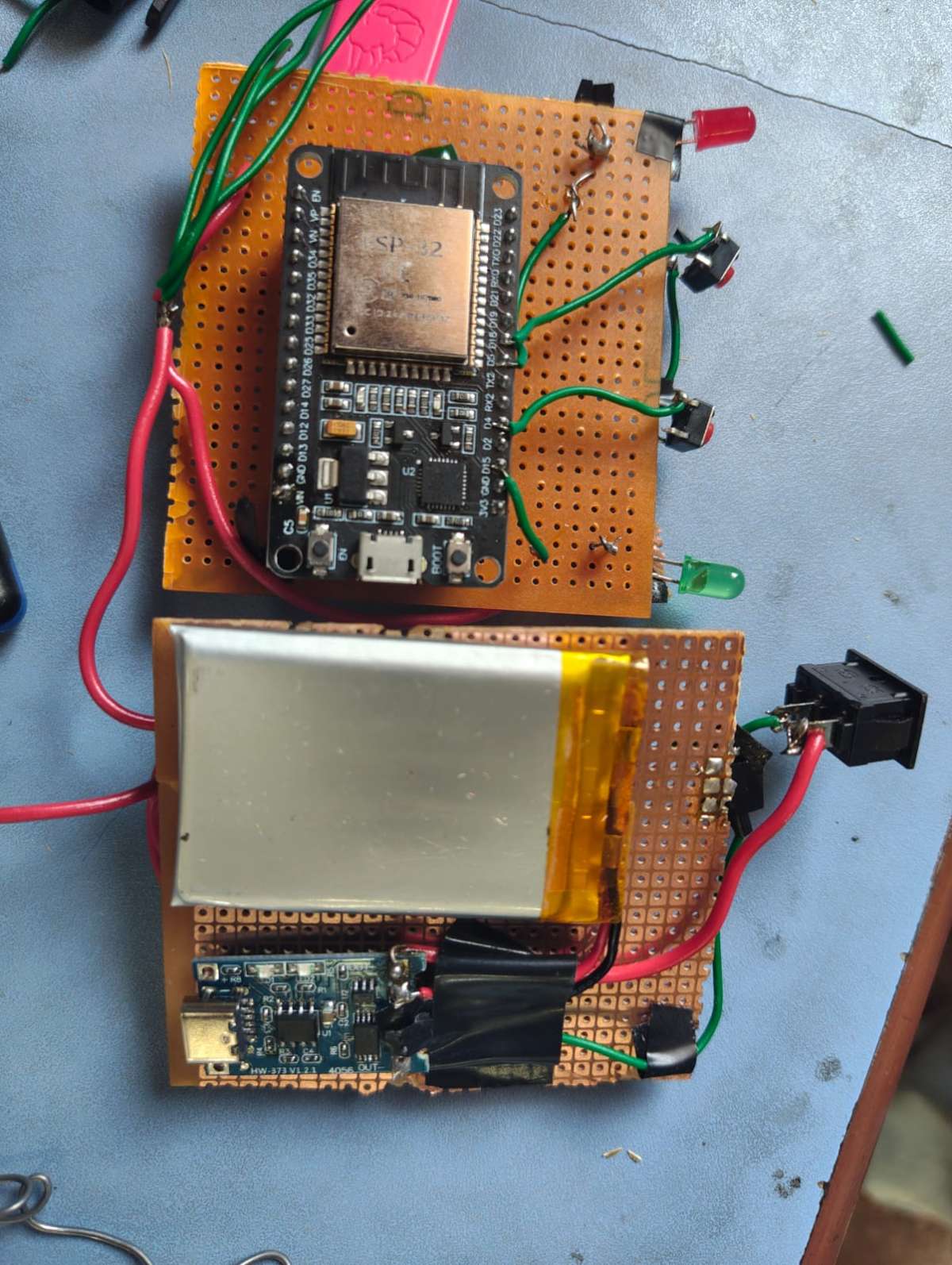
Hardware Implementation
The final prototype integrates sensing, processing, communication, and power management modules into a compact wearable platform.
The device includes:
- ESP32 Controller
- MPU6050 Sensor
- MAX30102 Sensor
- TP4056 Charging Module
- LiPo Battery
- SOS and Cancel Buttons
- Status LEDs
The prototype was tested under multiple operating conditions to evaluate reliability and response time.
.jpeg)
Test Results
The system was evaluated under various real-world scenarios to validate detection accuracy and communication reliability.
| Test Category | Result |
|---|---|
| Fall Detection | All test falls successfully detected |
| Running / Jumping | No false alerts observed |
| Heart Rate Monitoring | Stable and continuous operation |
| High Heart Rate Event | Alert successfully generated |
| Low Heart Rate Event | Alert successfully generated |
| GPS Location Sharing | Successful |
| Automatic Calling | Successful |
| SMS Notification | Successful |
| End-to-End Alert Latency | 3–6 Seconds |
The results demonstrate reliable operation of the wearable safety system and effective emergency communication.
Cost Analysis
| Component | Cost (₹) |
|---|---|
| ESP32 | 450 |
| MPU6050 | 120 |
| MAX30102 | 350 |
| LiPo Battery | 400 |
| TP4056 Module | 40 |
| Buttons, LEDs, Passive Components | 100 |
| Miscellaneous Hardware | 500 |
| Total Cost | 1960 |
The complete system was developed at a significantly lower cost than many commercial wearable safety solutions.
Key Innovations
- Fully automated emergency detection without user intervention.
- Simultaneous monitoring of motion and physiological parameters.
- Three independent emergency detection mechanisms.
- Automatic calling and SMS transmission.
- GPS location sharing through Google Maps links.
- Cloud-connected emergency communication architecture.
- Low-cost implementation suitable for large-scale adoption.
Future Roadmap
Future improvements planned for the system include:
- GSM-based backup communication using SIM800L.
- Custom PCB development for miniaturization.
- AI-based emergency detection using TensorFlow Lite.
- Voice distress keyword recognition.
- Camera-assisted emergency evidence collection.
- iOS application support.
- Advanced battery optimization techniques.
Conclusion
The Smart Women Safety Wearable Device successfully demonstrates a practical and affordable solution for automated emergency detection and response. By combining motion sensing, health monitoring, cloud connectivity, GPS location sharing, and automated communication, the system provides immediate assistance during critical situations without requiring manual user intervention.
The project highlights how embedded systems, IoT technologies, and mobile applications can be integrated to create an effective real-time personal safety platform capable of improving emergency response and enhancing user security.
The companion app is developed in Flutter for Android. Key features include:
- Real-time Firebase listener running in the background — responds to alerts even when the app is minimized
- Automatic GPS location retrieval and Google Maps link generation upon alert trigger
- Sequential emergency calling — calls Contact 1, waits 10 seconds, then calls Contact 2
- Automatic SMS with alert type, timestamp, and live location link sent to all registered contacts
- One-tap access to national emergency helplines: Police (100), Ambulance (108), Women Helpline (1091), Fire (101), Emergency (112)
- Local contact storage using Shared Preferences for offline availability
- Alert reset mechanism to prevent repeated triggering after SOS completion