
A PID controller continuously calculates an error value as the difference between a desired setpoint and a measured process variable and applies a correction based on proportional, integral, and derivative terms.
In our case, the MPU6050 sensor collects data of the position (more precisely the angle) of the device and sends that data to the microcontroller which performs calculations based on previously given algorithms and constants, and sends the result to the electric motor, which with its movement tends to hold the device in the desired position. This loop is performed very quickly so that the device is stable in a vertical position. Nuts and bolts are added to the wheel in order to increase its weight, thus increasing the impact of the rotation on the whole device. This project is open source and the original code can be downloaded from GitHub https://github.com/remrc/One-Axis-Reaction-Wheel-Stick.
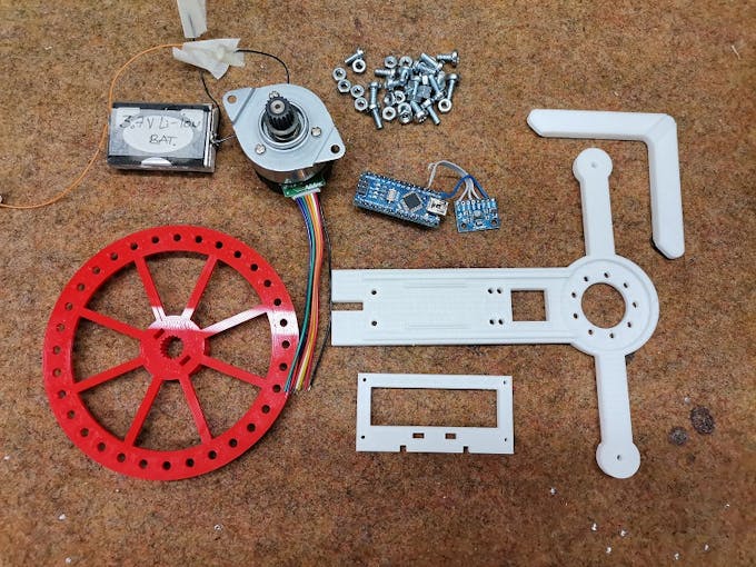
The device is simple to build and contains only a few components:
- Arduino Nano microcontroller
- MPU6050 Gyroscope + Accelerometer sensor module
- Nidec 24H brushless motor
- Buzzer
- 3pcs Lithium-Ion Batteries connected in series
- and 3Dprinted parts
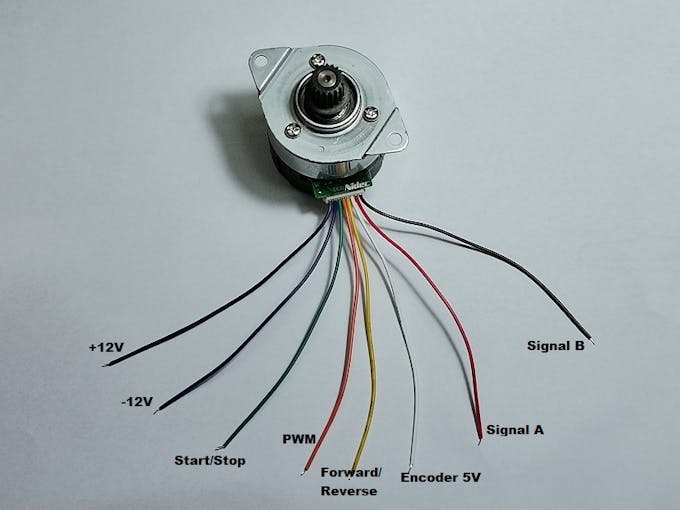
One note about the motor, ignore the colors of the wires and follow the pinout shown in the given picture.
The device starts in this (lying) position and we wait until we hear two short beeps, which indicate that it is ready. Depending on the placement and weight of the batteries and the characteristics of the sensor itself, during the first activation the device will probably not be completely stable and will swing left and right. To stabilize, it is necessary to experiment with the values of floatX1, floatX2, and floatX3 in the code. If it is well tuned even if we try to mechanically shift it to an unbalanced state, it returns automatically to a state of equilibrium. You can download 3D print. STL files at: https://www.thingiverse.com/thing:5361714
Video Link: