SOCIAL DISTANCING INDICATOR
DESCRIPTION:
For the upcoming generation, social distancing indicator is very effective for humans. The government insists and is mandatory to do the social distance. Our project may use for them to reduce health issues.
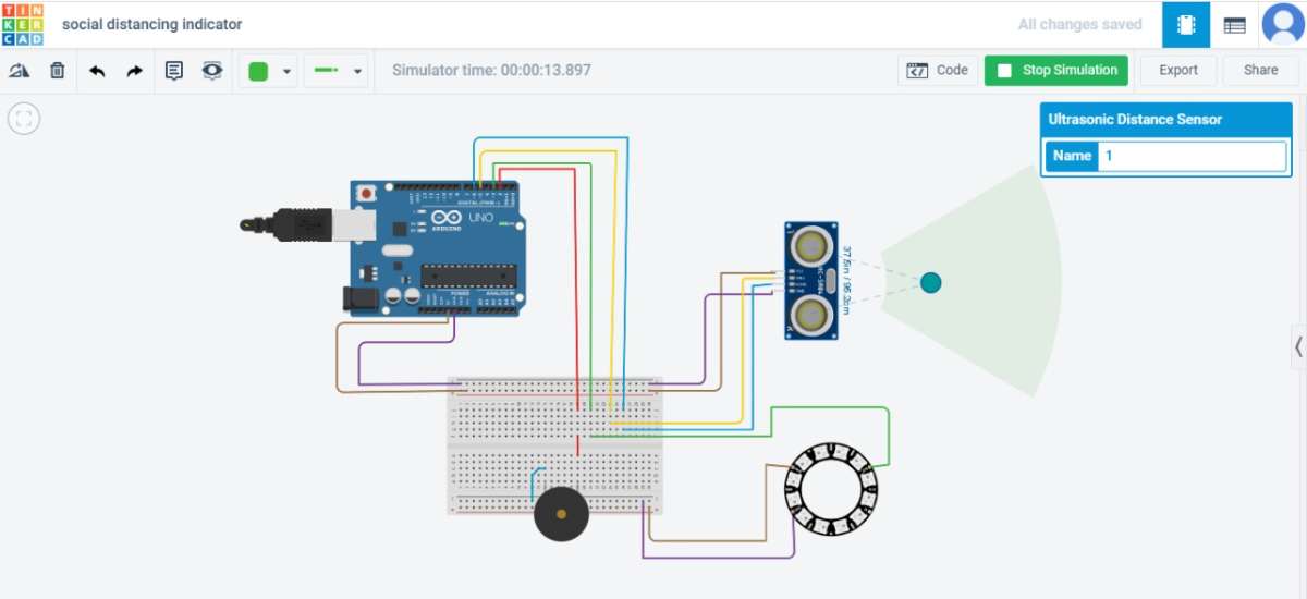
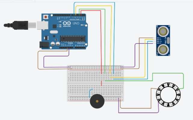
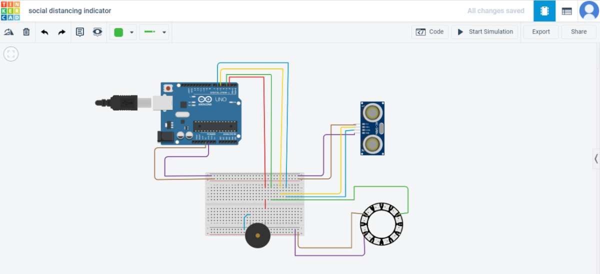
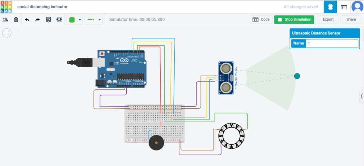
CIRCUIT DIAGRAM:
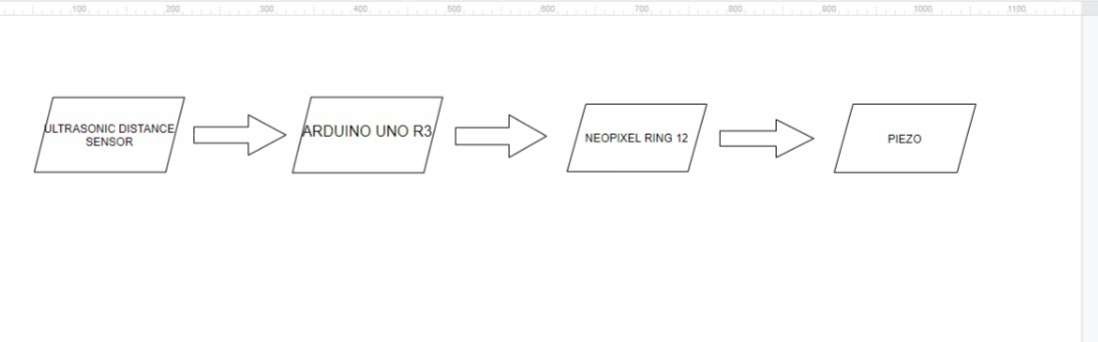
BLOCK DIAGRAM:
https://www.tinkercad.com/things/19f8IbGBpsl
EXPLANATION:
1) Pick the components :
- Breadboard
- Arduino UNO R3
- Ultrasonic Distance sensor
- Piezo
- Connecting Wires
- Neo Pixel ring 12
2) Arrange in order to form a social distancing circuit.
3) While proceeding the Arduino Uno D2 pin(Red wire) is connected to the breadboard.
4) The green wire Arduino Uno D3 pin is connected to the output of the Neo pixel ring 12.
5) The yellowish wire of the Arduino Uno D5 pin is connected to the ultrasonic distance sensor (trigger).
6) The blue wire of the Arduino Uno D6 pin is connected to the ultrasonic distance sensor (echo).
7) The purple wire of the Arduino Uno (ground) is connected in the series with the Ultrasonic distance sensor and Neo pixel ring 12 in the ground.
8) The purple wire of the Arduino Uno (ground) is connected in the series with the Ultrasonic distance sensor and Neo pixel ring 12 in the ground & Neo pixel 12 rings (power).
9) The Red wire of the Arduino Uno D2 pin is connected in series with the piezo buzzer.
10) While executing the circuit, we obtain and recognize the perfect output.
STEP 1:
STEP 2:
STEP 3: