Smart Gas Detector
I am a student and I wanted to make a small but useful safety project that I can actually use at home. That’s how I got the idea of a Smart Gas Leak Detector using ESP32, MQ-2 gas sensor and Blynk. My aim was to detect gas leaks early and also get a notification on my phone.
Step 1: Planning and collecting components
First, I finalized the basic idea:
- Sense gas using MQ-2 sensor
- Use ESP32 as the main controller
- Show status with RGB LED + buzzer
- Send live data and alerts to Blynk app
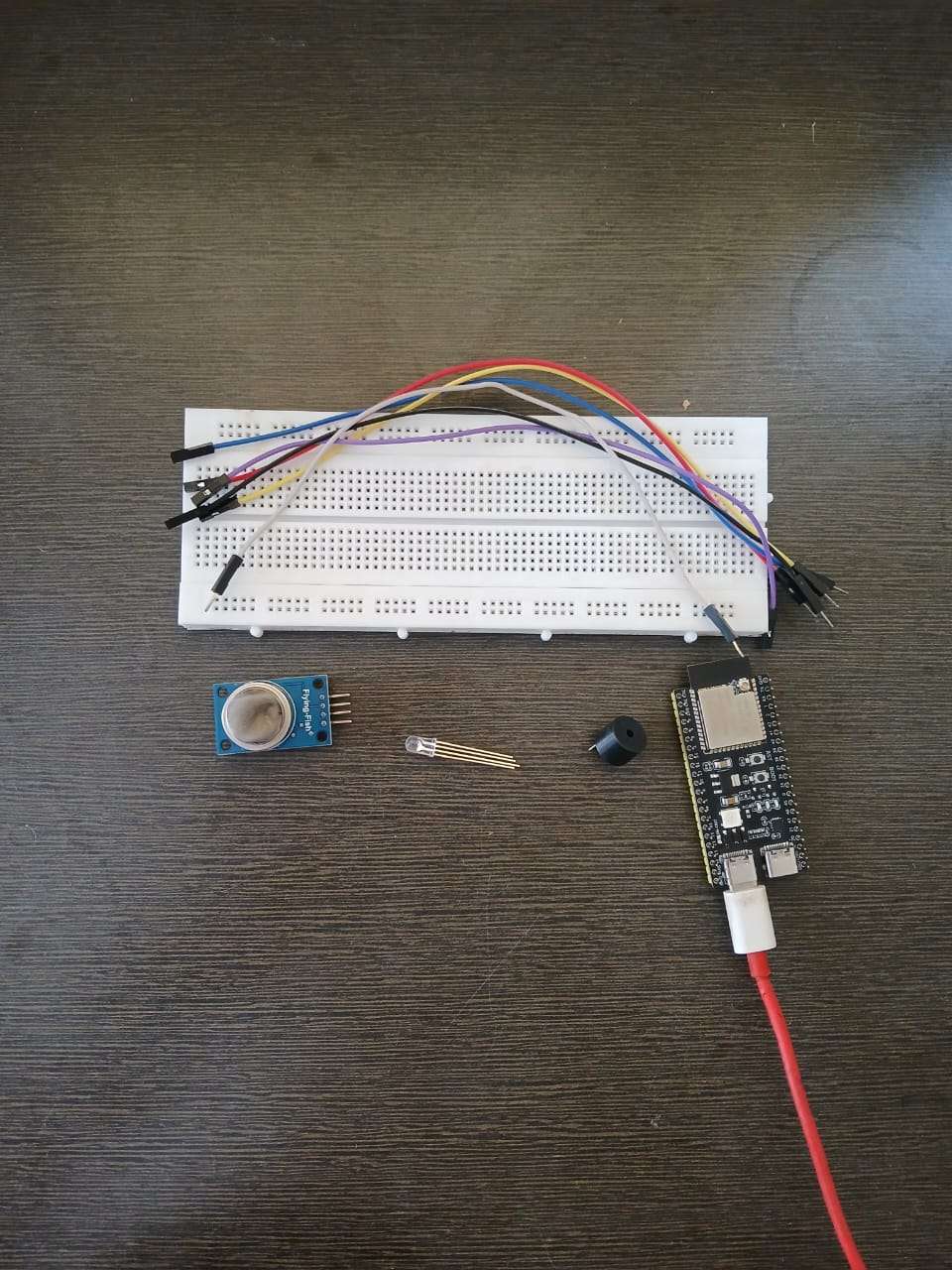
After that I collected all the components – ESP32 board, MQ-2 gas sensor, RGB LED, buzzer, resistors, breadboard, jumper wires and a USB cable.
MyLists | DigiKey – Component List
Here is the complete DigiKey MyList containing all the components used in this Smart Gas Leak Detector project:
https://www.digikey.in/en/mylists/list/HZAQGU7QML
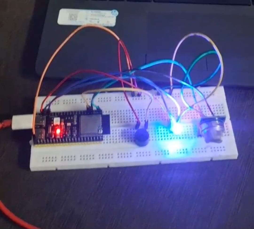
Step 2: Making the circuit on breadboard
Next, I started wiring everything on a breadboard.
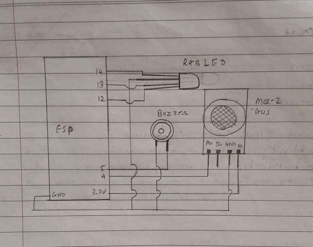
- I connected the MQ-2 sensor VCC and GND to the ESP32, and its analog output pin to GPIO 4.
- Then I connected the RGB LED pins to GPIO 12, 13 and 14 through resistors.
- The buzzer positive pin went to GPIO 5, and the negative pin went to GND.
- Finally, I powered the ESP32 from my laptop using a USB cable.
For the circuit understanding, I also drew a simple hand-drawn schematic in my notebook using pen, showing ESP32, MQ-2, RGB LED and buzzer connections. Then I clicked a clear photo of that page.
.jpeg)
Step 3: Programming the ESP32
After the hardware was ready, I moved to the coding part.
I used Arduino IDE as the programming platform. I added ESP32 board support, installed the Blynk library, and then wrote my code for the project. The code does these main things:
- Connects ESP32 to my WiFi and Blynk cloud
- Reads the analog value from the MQ-2 sensor
- Calculates a baseline and sets a dynamic threshold
- Decides if the air is safe, warning or danger
- Controls the RGB LED and buzzer based on gas level
- Sends sensor values and status to the Blynk app
- Triggers a Blynk event to send notification on gas leak
After updating my Blynk template details and WiFi credentials, I uploaded the code to the ESP32 and opened the Serial Monitor to check if everything was running fine.
.png)
Step 4: Setting up Blynk app and dashboard
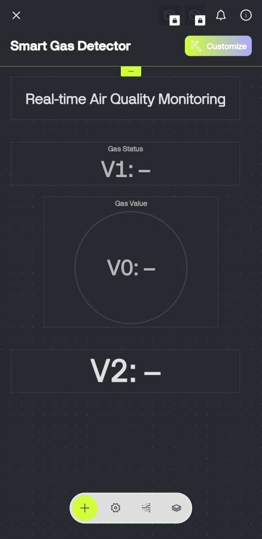
On my phone, I opened the Blynk app and created a new project with ESP32 as the device. I added these widgets:
- A value display for sensor analog value (V0)
- A text/label for status (“Air Safe”, “Warning”, “Danger”) on (V1)
- A value display for the threshold (V2)
I also created a Blynk event called gas_alert so that when the gas level goes above the danger threshold, I get a notification on my mobile.
Then I linked this project with my ESP32 code using the Blynk Auth Token.
.png)
Step 5: Calibration and testing with real gas
When I powered the system, it first went into self-calibration mode. For a few seconds, I kept the sensor in normal clean air so that the code could measure multiple values and calculate a baseline. Then it automatically set a threshold = baseline + 200.
After that, I started testing:
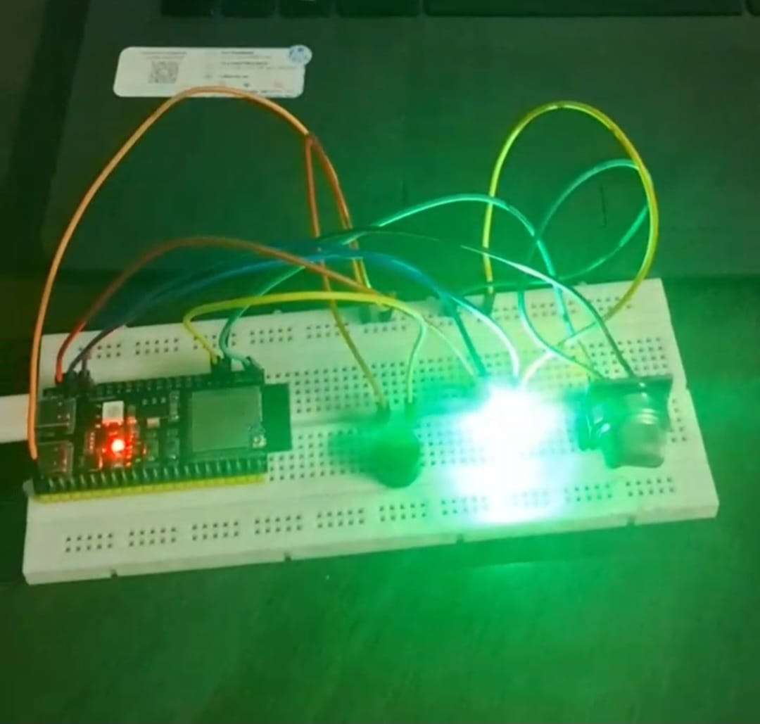
- In normal air, the green LED turned ON, buzzer remained OFF and Blynk showed “✅ Air Safe”.
- When I brought a small amount of gas/smoke near the MQ-2 sensor, first the blue LED turned ON and buzzer gave a soft warning beep, and Blynk showed “⚠️ Warning: Gas Level Rising”.
- When the gas level went above the threshold, the red LED turned ON, the buzzer gave a loud alarm, and I received a Blynk notification saying gas leak detected.
I repeated this test a few times to make sure the readings were consistent and the notification system was working reliably.

Step 6: Final demo and improvements
After everything worked properly, I recorded a short demo video showing:
- The complete hardware setup
- Live values on the Blynk app
- Safe → warning → danger transitions
- The notification coming on my phone
Now the project can be used as a basic kitchen gas leak warning system. In future, I can put it in a proper enclosure, add more sensors like temperature or flame, and make it fully ready for real-life use.