Introduction
Modern agricultural tractors require constant attention from the operator, especially when working in environments where people, animals, or equipment may unexpectedly enter the vehicle's path. The goal of this project was to develop a low-cost semi-autonomous safety system that can detect obstacles and automatically stop an electric tractor before a collision occurs.
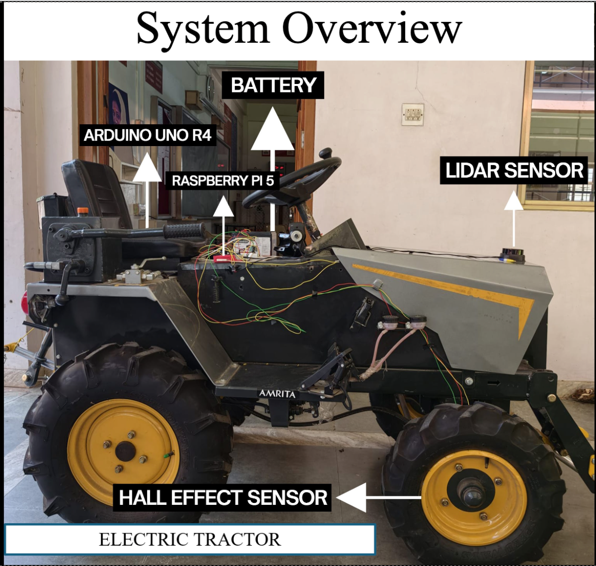
The project was implemented on a Sukoon Haldar 750 Mini Electric Tractor using a Raspberry Pi 5, an industrial-grade RPLIDAR S2E, and an Arduino UNO R4 running Zephyr RTOS. Instead of making the tractor fully autonomous, the focus was placed on adaptive cruise control and automatic obstacle avoidance while allowing the operator to retain steering control. This approach significantly reduced system cost and complexity while still providing meaningful safety improvements.
Step 1: Understanding the Tractor Electronics
Before adding any automation, I first needed to understand how the tractor was built.
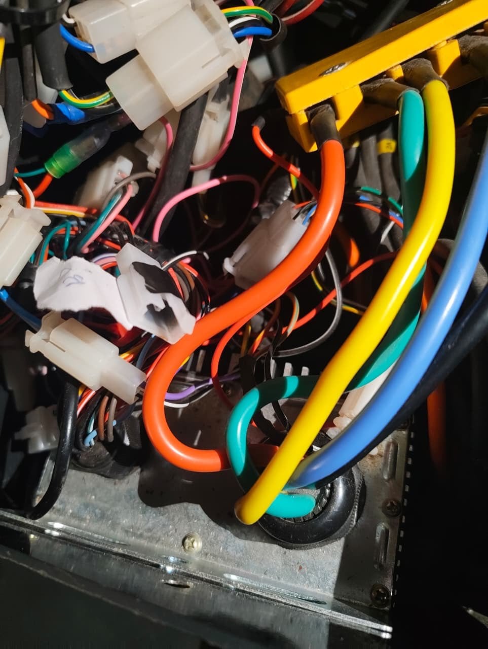
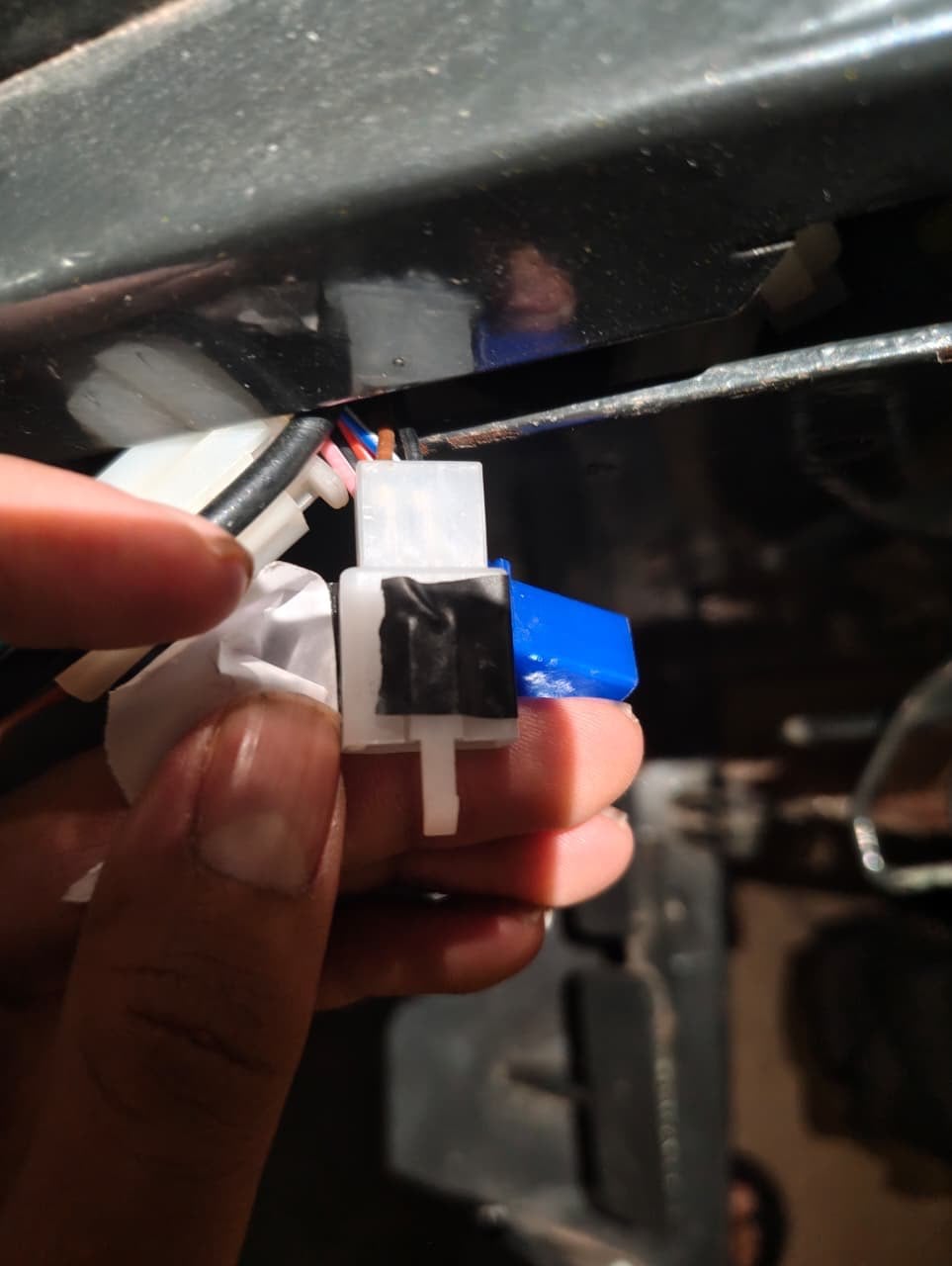
The motor controller was located inside a compartment near the steering column. After opening the enclosure, I carefully traced the wiring to identify the throttle signal, power connections, and control interfaces. Since wiring documentation was unavailable, I followed individual wires and compared them with common BLDC motor controller wiring conventions.
Initially, I assumed the braking system was electronically controlled. However, after examining the vehicle more closely, I discovered that the tractor used a completely mechanical brake system. This meant I could not simply send a braking command electronically.
To solve this problem, I decided to use a linear actuator that could physically press the brake mechanism whenever an emergency stop was required.
(Trick:Even though the wires seem messy, We can backtrack the wiring eg- To Find the acceleration wiring we tugged at the exposed wire and found out the corresponding wire and verified using the data sheet)
Step 2: Hardware Selection
The next step was choosing hardware capable of detecting obstacles while keeping costs reasonable.
After comparing several options, I selected the RPLIDAR S2E. Unlike cameras, LiDAR can accurately measure distance regardless of lighting conditions, making it more suitable for outdoor agricultural environments.
For processing, I chose a Raspberry Pi 5 because it provides enough computing power to process LiDAR data in real time while remaining affordable and easy to develop on.
The main components used in the project were:
Raspberry Pi 5(8gb-16 gb ram)
.jpg)
RPLIDAR S2E LiDAR
.png)
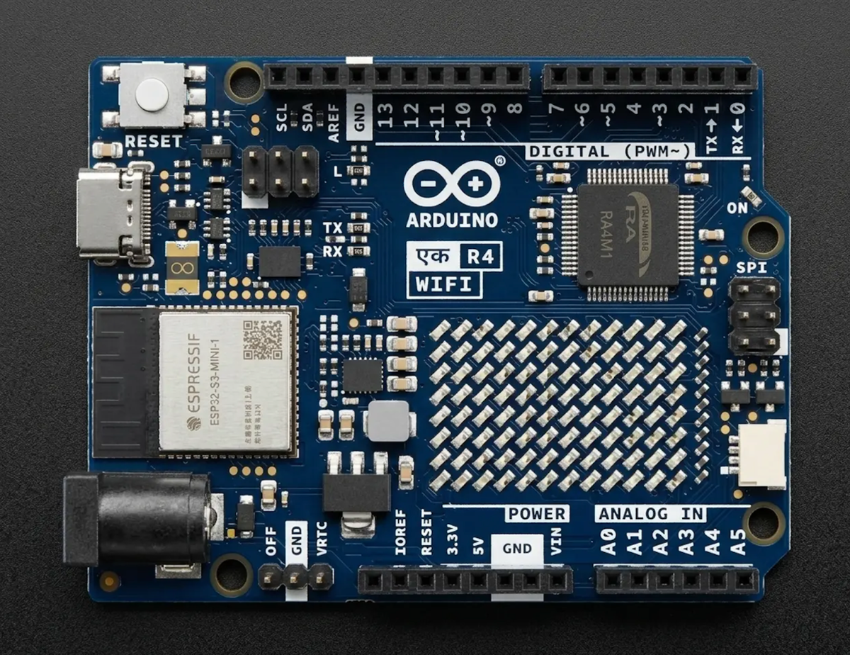
Arduino UNO R4
- Linear brake actuator( Any generic one)
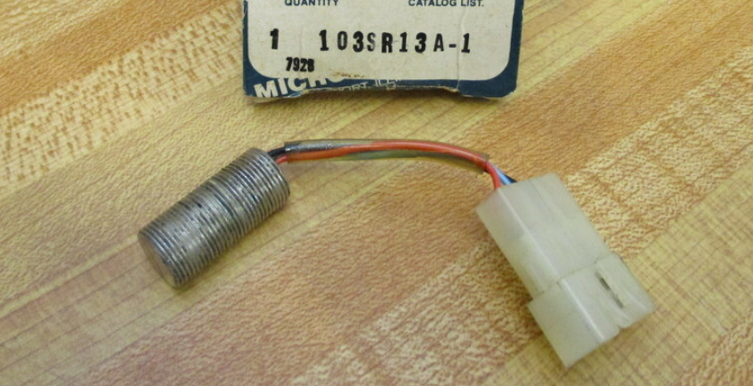
- Hall-effect wheel speed sensor( 103sr13A)
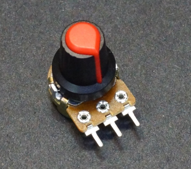
- Potentiometer for speed selection( Preferably with a knob)
Other misc(power cables and sd card for the raspberry pi )
Step 3: Raspberry Pi 5 Setup and Operating System Configuration
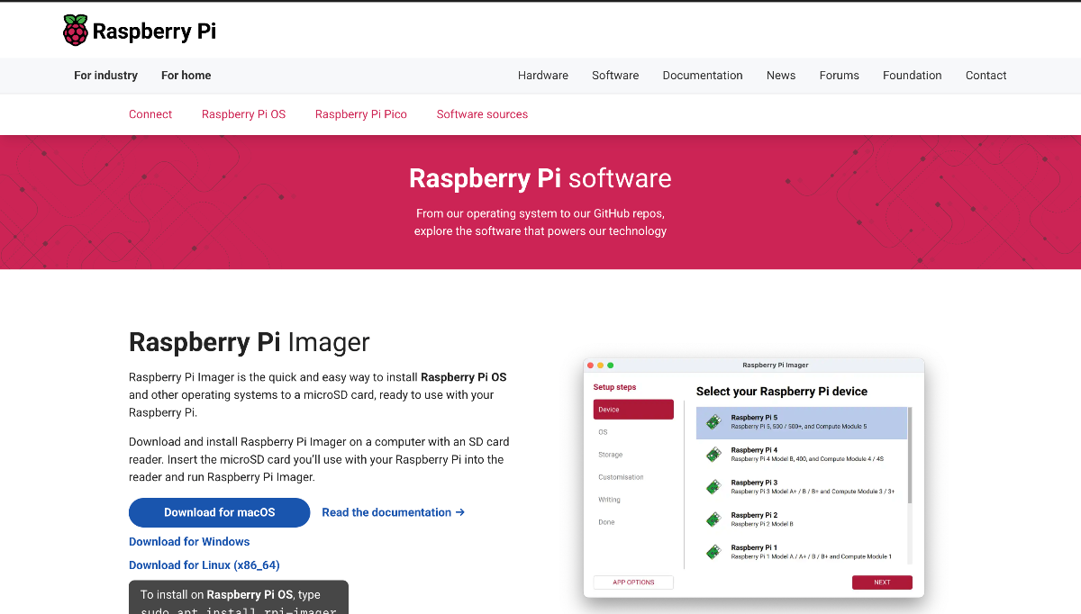
Pi imager does not enable ssh automatically if you are using the OS version with GUI ,So we had to connect a Display for the initial step, and manually enable ssh
The Raspberry Pi 5 was selected as the primary perception and decision-making computer due to its high processing capability, low power consumption, and excellent Linux support. Ubuntu 24.04 LTS was installed using the Raspberry Pi Imager and flashed onto a high-speed microSD card.(This can be found on Raspberry pi's Official web page)
During installation, SSH was enabled to allow remote access without requiring a monitor or keyboard. After connecting the Raspberry Pi to the local Wi-Fi network, its IP address was identified, and all development and deployment activities were performed remotely using:
ssh username@<raspberry-pi-ip>
This headless setup simplified development and allowed software updates, debugging, and monitoring directly from a laptop without physically accessing the tractor.
Step 4: RPLIDAR S2E Integration
For obstacle detection, the project utilizes the RPLIDAR S2E industrial-grade 2D LiDAR sensor. The sensor was selected because it offers a 360-degree field of view, long detection range, industrial reliability, and Ethernet-based communication. Compared to USB-based LiDARs, Ethernet communication provides greater stability, reduced latency, and better noise immunity in agricultural environments.
The official SLAMTEC SDK was used for development:
RPLIDAR SDK Repository:
https://github.com/Slamtec/rplidar_sdk
The SDK provides low-level access to scan data, device configuration, and networking functionality, allowing custom obstacle-detection algorithms to be developed without relying on heavyweight middleware.
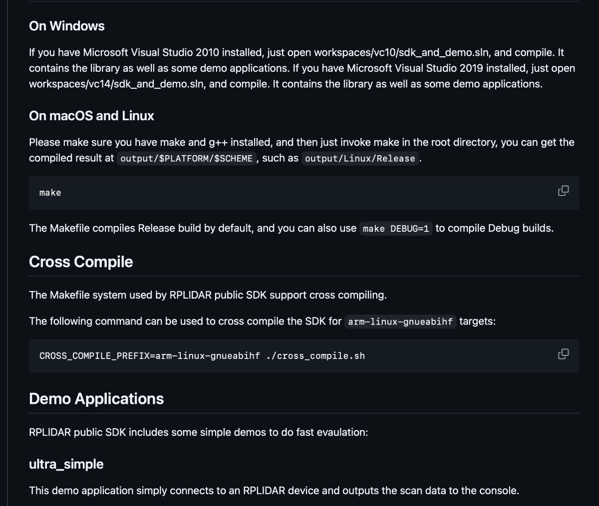
The Rplidar github repo has good demo applications which were used to understand the structure and the way the sdk worked
All the specific commands can be found in the link above
Step 5: Physical Installation of the LiDAR
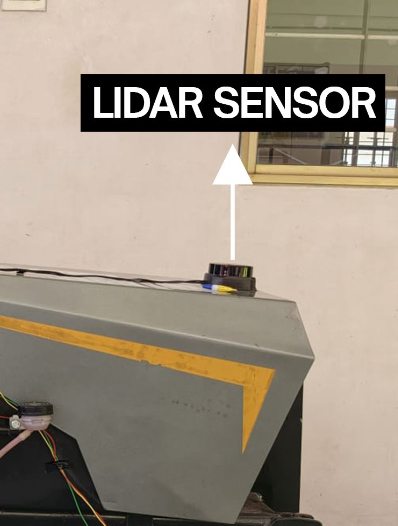
LiDAR placement was one of the most critical design decisions in the project.
The RPLIDAR S2E was mounted near the front-center region of the tractor at an elevated position above the hood. This location provided an unobstructed forward field of view while minimizing interference from tractor components.
Several mounting locations were evaluated before finalizing the design. Mounting the sensor too low resulted in frequent detections of uneven terrain and vegetation, while mounting it too high reduced sensitivity to low-lying obstacles.
The final mounting position was selected to ensure:
- Maximum forward visibility.
- Reduced occlusion from tractor components.
- Reliable detection of humans, animals, rocks, and field equipment.
- Stable operation under vibration.
Since the tractor itself occupies a portion of the LiDAR's 360-degree field of view, scan sectors corresponding to the rear region and structural elements of the tractor were intentionally excluded from obstacle processing.
This prevented the system from continuously detecting its own chassis and generating unnecessary emergency stops.
Step 6: Ethernet Configuration and LiDAR Networking
.jpeg)
The RPLIDAR S2E communicates through Ethernet and therefore requires both devices to be on the same subnet.
The LiDAR operates using a fixed network configuration. To establish communication, the Raspberry Pi Ethernet interface was configured with a static IP address:
sudo ip addr add 192.168.11.1/24 dev eth0
sudo ip link set eth0 up
After configuration, both the Raspberry Pi and the LiDAR existed within the same network segment, enabling direct communication.
The physical connection was straightforward:
- Ethernet cable connected from the RPLIDAR S2E to the Raspberry Pi 5 Ethernet port.
- Ethernet interface manually configured.
- Connectivity verified through SDK discovery tools.
- Real-time scan acquisition initiated through the RPLIDAR SDK.
Once communication was established, the Raspberry Pi continuously received laser scan packets from the sensor and processed them in real time. if the above command is successful run the following command:
ultra_simple <serial_port_device>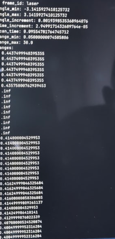
If the connection is successful you should be able to see the lidar printing the points above
Step 7: Obstacle Detection Algorithm:
Go to the same workspace and execute the following example to see the lidar build a map:
SDK Initialization and Termination
#include "sl_lidar.h"
#include "sl_lidar_driver.h"

int main(int argc, char* argv)
{
    ///  Create a communication channel instance
    IChannel* _channel;
    Result<ISerialChannel*> channel = createSerialPortChannel("/dev/ttyUSB0", 115200);
    ///  Create a LIDAR driver instance
    ILidarDriver * lidar = *createLidarDriver();
    auto res = (*lidar)->connect(*channel);
    if(SL_IS_OK(res)){
        sl_lidar_response_device_info_t deviceInfo;
        res = (*lidar)->getDeviceInfo(deviceInfo);
        if(SL_IS_OK(res)){
            printf("Model: %d, Firmware Version: %d.%d, Hardware Version: %d\n",
            deviceInfo.model,
            deviceInfo.firmware_version >> 8, deviceInfo.firmware_version & 0xffu,
            deviceInfo.hardware_version);
        }else{
            fprintf(stderr, "Failed to get device information from LIDAR %08x\r\n", res);
        }
    }else{
        fprintf(stderr, "Failed to connect to LIDAR %08x\r\n", res);
    }
    // TODO

    /// Delete Lidar Driver and channel Instance
    * delete *lidar;
    * delete *channel;
}
Start spinning motor
The LIDAR is not spinning by default for A1, A2 and A3. Method startMotor() is used to start this motor. If the Lidar is S1 or S2, please skip this step.
For RPLIDAR A1 series, this method will enable DTR signal to make the motor rotate; for A2 and A3 serieses, the method will make the accessory board to output a PWM signal to MOTOR_PWM pin.
lidar->startMotor();
// TODO
lidar->stopMotor();
Start scan
Slamtec RPLIDAR support different scan modes for compatibility and performance. Since RPLIDAR SDK 1.6.0, a new API getAllSupportedScanModes() has been added to the SDK.
std::vector<LidarScanMode> scanModes;
lidar_drv->getAllSupportedScanModes(scanModes);
You can pick a scan mode from this list like this:
lidar->startScanExpress(false, scanModes[0].id);
Or you can just use the typical scan mode of RPLIDAR like this:
LidarScanMode scanMode;
lidar->startScan(false, true, 0, &scanMode);
Grab scan data
When the RPLIDAR is scanning, you can use grabScanData() and grabScanDataHq() API to fetch one frame of scan. The difference between grabScanData() and grabScanDataHq() is the latter one support distances farther than 16.383m, which is required for RPLIDAR A2M6-R4 and RPLIDAR A3 series.
The
grabScanDataHq()API is backward compatible with old LIDAR models and old firmwares. So we recommend always using this API, and usegrabScanData()only for compatibility.
sl_lidar_response_measurement_node_hq_t nodes[8192];
size_t nodeCount = sizeof(nodes)/sizeof(sl_lidar_response_measurement_node_hq_t);
res = lidar->grabScanDataHq(nodes, nodeCount);

if (IS_FAIL(res))
{
    // failed to get scan data
}

A visualisation of what The LIDAR sees,Whenever a new object comes into the line of sight the map gets updated
.jpeg)
The LiDAR continuously generates a 360-degree point cloud representing the surrounding environment.
Each scan consists of distance measurements associated with corresponding angular positions. The software processes every scan frame and divides the environment into predefined safety sectors.
Only the forward operational region of the tractor is considered for obstacle detection. Scan points corresponding to the rear section and the tractor's own physical structure are ignored.
.jpeg)
For each incoming scan:
- Distance measurements are extracted.
- Rear-sector measurements are discarded.
- Measurements inside the tractor footprint are ignored.
- Remaining points are compared against a configurable safety threshold.
- Potential obstacles are tracked over multiple scan frames.
An obstacle is considered valid only if it appears consistently across several consecutive scans.
This temporal filtering mechanism was implemented to eliminate false positives caused by:
- Dust particles.
- Vegetation movement.
- Temporary reflections.
- Sensor noise.
- Rain droplets.
- Uneven ground surfaces.
Only when an obstacle remains present for multiple consecutive frames is an emergency stop command generated.
This significantly improved reliability during field testing and prevented unnecessary braking events.
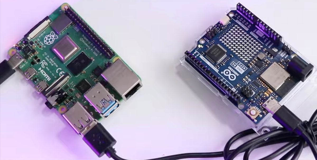
Step 8: Communication Between Raspberry Pi and Controller
Insert the following code and try sending G and s through arduino's serial monitor
/* Arduino Uno R4 - Zero Latency Speed Controller */
const int dacPin = A0;

// 12-bit DAC: 0-4095
const int V_IDLE = 655;   // 0.8V
const int V_1MPH = 1147;  // 1.4V

int currentOutput = V_IDLE;
int targetOutput = V_IDLE;
bool safetyStop = true;
unsigned long lastUpdate = 0;

void setup() {
  analogWriteResolution(12);
  Serial.begin(9600);
  analogWrite(dacPin, V_IDLE);
}

void loop() {
  // ZERO LATENCY READ
  if (Serial.available() > 0) {
    char c = Serial.read();
    if (c == 'S') {
      safetyStop = true;
      targetOutput = V_IDLE;
      currentOutput = V_IDLE; // Instant voltage drop
      analogWrite(dacPin, V_IDLE);
    }
    else if (c == 'G') {
      safetyStop = false;
      targetOutput = V_1MPH;
    }
  }

  // ACCELERATION RAMP (Only when clear)
  if (!safetyStop && millis() - lastUpdate > 30) {
    if (currentOutput < targetOutput) {
      currentOutput += 15; // Faster increment for better response
      if (currentOutput > targetOutput) currentOutput = targetOutput;
      analogWrite(dacPin, currentOutput);
    }
    lastUpdate = millis();
  }
}
Once a valid obstacle is detected, the Raspberry Pi immediately transmits a stop command to the real-time controller through USB serial communication.
The controller continuously listens for:
- GO commands
- STOP commands
Under normal operation, the controller regulates vehicle speed according to the user-selected speed setting and Hall-effect sensor feedback.
When a STOP command is received:
- Throttle output is instantly reduced.
- Cruise control is overridden.
- The braking actuator is activated.
- The tractor enters a safe stopped state.
When the obstacle disappears and the area becomes clear, the controller receives a GO command and normal operation resumes.
Step 9: Real-Time Controller Development Using Zephyr RTOS:
While the Raspberry Pi handled perception, I needed a dedicated controller to manage safety-critical functions.
For this purpose, I used an Arduino UNO R4 running Zephyr RTOS. The controller manages speed regulation, Hall-effect sensor monitoring, throttle control, communication, and emergency braking.
Using an RTOS allowed me to separate the software into multiple tasks with different priorities. The emergency braking task was assigned the highest priority to ensure that obstacle detection always resulted in an immediate response.
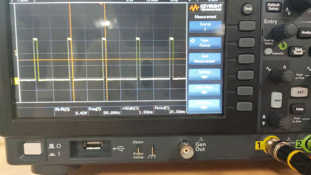
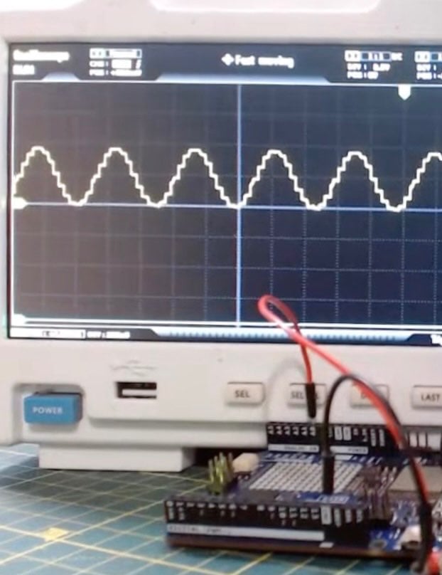
Oscilloscope showing the output of the RTOS as a Square wave as the actual spped increasses beyond set speed the period decreases
By running as an independent RTOS task, speed regulation remains stable even when other parts of the system are busy.
Integration with the Tractor
The original throttle signal line connected to the BLDC motor controller was intercepted and routed through the controller.
The UNO R4 DAC output became the new throttle source
Connect the A0 DAC pin of the Arduino to the oscilloscope to test the DAC output
This allowed the controller to regulate acceleration while still preserving operator control through the speed-selection potentiometer.
The controller therefore acts as an intelligent intermediary between the operator and the motor controller.
Safety and Reliability Benefits
Using Zephyr RTOS provided several advantages compared to a conventional Arduino implementation:
- Predictable execution timing.
- Reliable multitasking.
- Fast emergency response.
- Improved software modularity.
- Easier future expansion.
- Increased operational safety.
The final architecture combines the computational power of the Raspberry Pi 5 with the deterministic behavior of Zephyr RTOS, creating a hybrid system capable of both intelligent perception and reliable real-time vehicle control.
Step 10: System Automation:
To ensure ease of deployment, startup scripts were configured on the Raspberry Pi using python .
During boot:
- Ethernet configuration is applied.
- LiDAR communication is initialized.
- Obstacle-detection software launches automatically.
- Controller communication is established.
- Monitoring services begin execution.
As a result, the operator only needs to power on the tractor. The complete perception, safety, and control system becomes operational automatically without requiring manual software intervention.