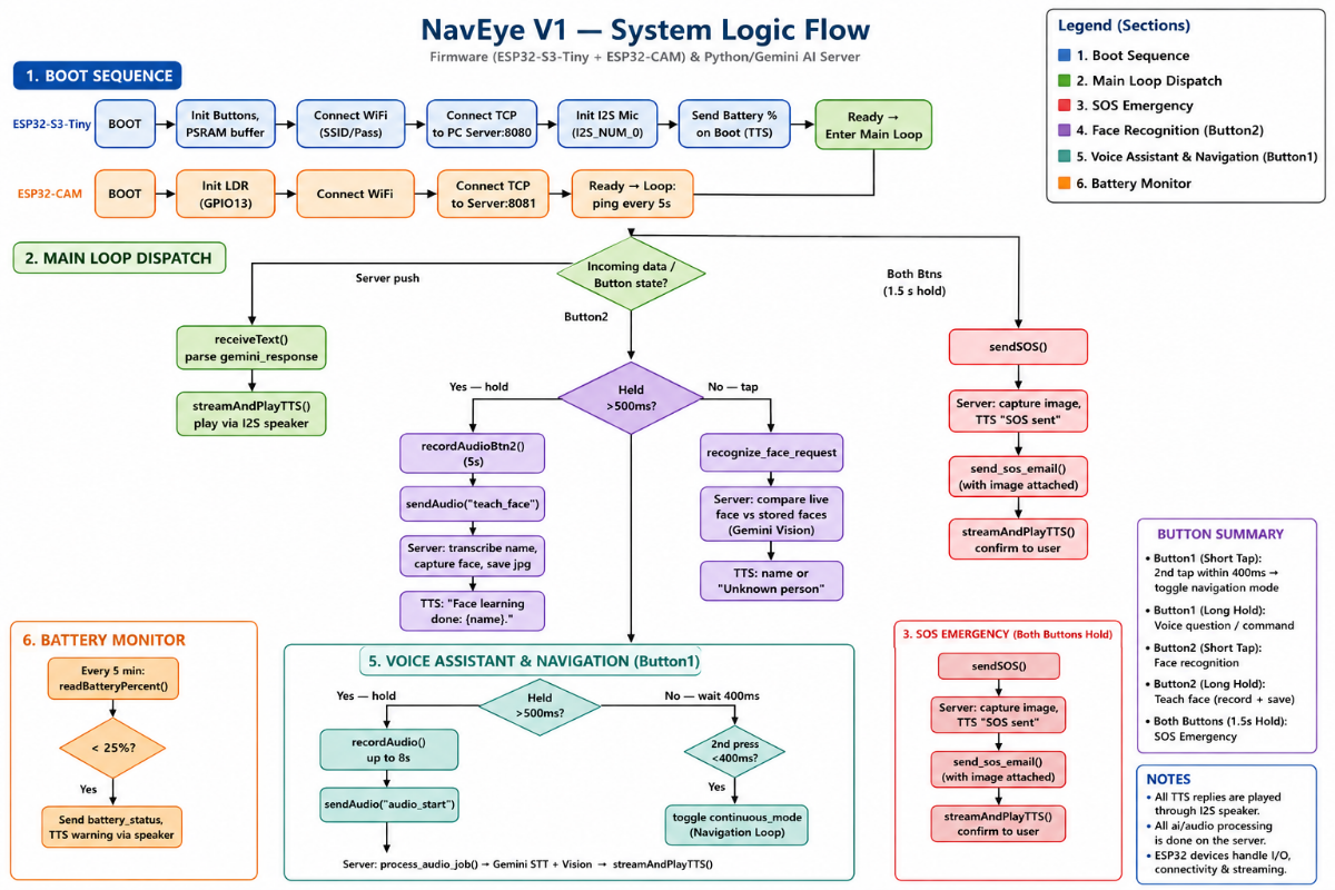



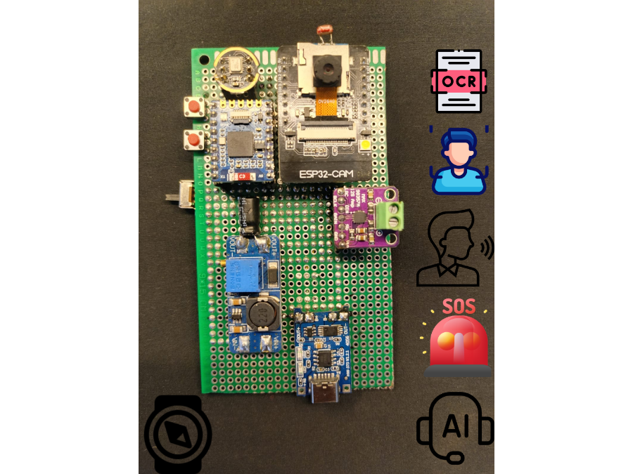
NavEye_V1 – Your AI Guide Beyond Sight
The NavEye V1 is a groundbreaking assistance technology designed to help people with visual impairments navigate more independently and interact better with their surroundings. This system boasts a range of features, including smart navigation, object recognition, optical character recognition for text reading, facial recognition, voice control, an SOS function, and an intelligent AI assistant.
Inspiration
Problem 1: –
For people with visual impairments, one of the challenges is identifying drugs when there’s no packaging designed specifically for them. Drug labels are usually small and not easily readable by touch, and instructions aren’t available in audio format either.
In many real-life situations, users rely on others or try to guess based on the shape and size of objects.
An analysis conducted on patients with visual impairment suggests that most face significant difficulties in managing medications. This was demonstrated by the participants' inability to accurately locate their drugs, missing doses, and even taking incorrect quantities of the medications. The majority lacked a proper system for managing their drugs.
.jpg)
Problem 2: –
Navigation happens to be among the greatest problems faced by visually impaired people. Lack of appropriate tactile guidance or audio assistance in both private and public areas such as offices, homes, and streets poses great problems when navigating. Even little things such as furniture pose significant problems and sometimes they step on objects and it gets broken.

Problem 3:-
It’s difficult to find items like keys, bottles, edible objects, or tools on a table without the ability to see. Many people with visual impairments rely on their memory or sense of touch to locate objects, but this isn’t very efficient.
AI-based object detection technologies are designed to help visually impaired individuals find their belongings by utilizing voice and camera functions.
.gif)
Solution to all these problems = Naveye_v1
Key Features
- Smart Navigation – Helps users move safely by identifying paths and obstacles.
- Object Detection – Recognizes and identifies objects in the vicinity in real time.
- OCR Text Reading – Reads printed text, signs, labels, and documents aloud.
- Face Recognition & Learning – Identifies known individuals and can learn new faces.
- AI Assistant – Answers questions, provides information, and helps with daily tasks.
- SOS Emergency System – Sends alerts and emergency notifications when assistance is needed.
- Real-Time Audio Feedback – Provides spoken instructions and notifications via a speaker
- Portable & Battery Powered – Designed for everyday use with a compact and mobile form factor.
- Image translation – Extracts text from images and translates it into the user’s preferred language.
- Voice Translation – Translates spoken language in real time, enabling communication across different languages.
- Battery Percentage Announcement – Announces battery percentage on startup and warns automatically when it runs low, so the user stays aware of power level without needing to check manually.
How Each Mode Helps Visually Impaired Users
1. AI Mode
Features:Gemini AI model support
- Real-time conversation with AI
- 100+ language support
- Audio/image translation
- Audio output via speaker
2. Continuous/Navigation Mode
Features:- Detects obstacles while walking
- Announces nearby objects
- Reads signs/text automatically
- Hands-free operation
- Improves safety and independence
3. Face Recognition Mode
Features:- Announces who's in front of the user
- Distinguishes known vs. unknown people
- Builds confidence in social interactions
- Secure identification in public/private spaces
- How it works:
- Long-press "Add New Face" button
- User speaks the name (e.g., "Kartik")
- Camera captures a sample image
- System extracts name from audio, saves image under that name
- Gemini AI compares live faces against stored profiles
- On match, speaker announces the person's name
4. SOS Emergency Mode
How it works:- User presses SOS button or triggers voice command
- Camera captures image
- Alert emailed with image attached
- Emergency contacts notified instantly
- Audio confirmation played ("SOS Sent")
- How it helps:
- Fast help during accidents or disorientation
- One-step emergency trigger
- Reduces dependence on others during crises
Image of components used: –
.png)
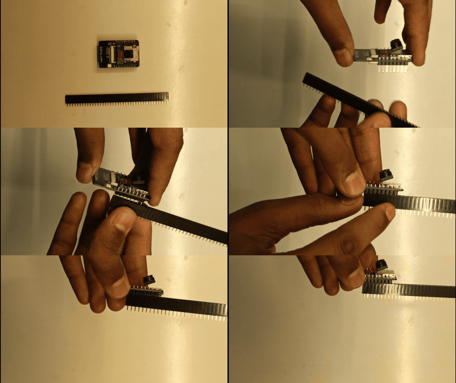
Step 1 — Trim Header Pins
Cut female header strips to match each component's pin count.
"Exampel"
Step 2 — Place & Solder Headers
Insert headers into perf board, solder all pins.
"Exampel"
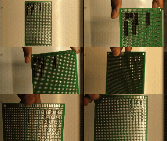
Step 3 — Place & Solder Other Components
Add TP4056, MT3608 buck converter, and buttons. Solder per circuit diagram.
"Example"
.gif)
Circuit Diagram
.png)
Step 4 — Mount Main Components
Place remaining main components onto the board per layout.
Exampel:-
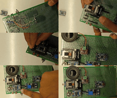
Circuit board assembly complete.
ESP32-S3 Firmware Setup
- Arduino IDE → File → Preferences → Additional Boards Manager URLs:
https://raw.githubusercontent.com/espressif/arduino-esp32/gh-pages/package_esp32_index.json.png)
- Tools → Board → Boards Manager → search "ESP32" → install esp32 by Espressif Systems (latest). Restart IDE if board list doesn't refresh.
.png)
- Open
NaveEye_V1.ino - Tools → Board → ESP32 → Waveshare ESP32-S3-Zero
- Connect via USB-C
- Tools → Port → select correct COM port
- Tools → USB CDC On Boot → Enable
- In code, set:
const char* ssid = "YOUR_WIFI_SSID";
const char* password = "YOUR_WIFI_PASSWORD";
const char* serverIP = "YOUR_PC_LAN_IP";  // from server console "Server IP" line
- Upload (→ arrow icon)
.png)
python server firmware
Setup: PC Server (Thonny IDE)
- Download Thonny: thonny.org (select your OS installer)
- Install and open Thonny
- Open the Nova server script (
File > Open) - In Thonny's Shell panel, run:
!pip install google-generativeai gtts requests- Press Enter, wait for install to finish
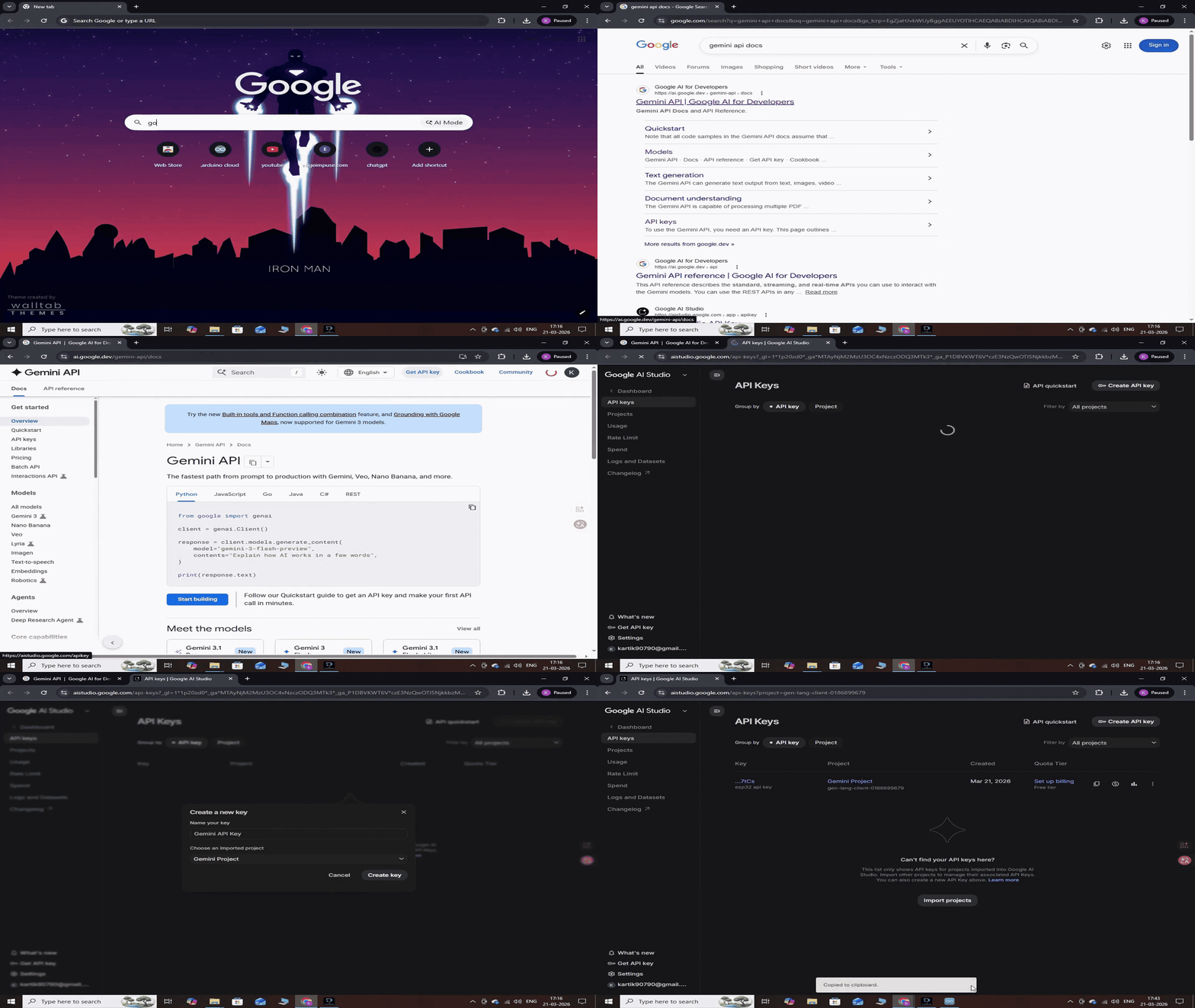
- Replace
GEMINI_API_KEYin the code with your own key - Get an API key by following this step: aistudio.google.com/apikey
- SOS Configuration — Step-by-Step
Location in code:
SOS_GMAIL_SENDER = "[email protected]" SOS_GMAIL_PASSWORD = "your_app_password" SOS_FAMILY_EMAILS = ["[email protected]"] SOS_DEVICE_NAME = "Naveye" SOS_USER_NAME = "Your Name"- 1.
SOS_GMAIL_SENDER - The Gmail account that sends the emergency alert. It's best to use a dedicated or secondary Gmail account rather than your primary personal one — that way, even if the credentials are ever exposed, your main account stays safe.
SOS_GMAIL_SENDER = "[email protected]"- 2.
SOS_GMAIL_PASSWORD— App Password (not your regular Gmail password) - Gmail no longer allows plain password login for SMTP, so you'll need to generate a 16-character App Password instead:
- Go to myaccount.google.com/security
- Under "How you sign in to Google," turn on 2-Step Verification (required before App Passwords become available)
- Once enabled, go to myaccount.google.com/apppasswords
- Under "Select app," choose Mail (or "Other" and name it "Naveye")
- Click Generate
- Google will show a 16-character code, like
abcd efgh ijkl mnop - Copy it exactly as shown (spaces are fine) and paste it into the code:
SOS_GMAIL_PASSWORD = "abcd efgh ijkl mnop"- This password only works for app/SMTP access — it can't be used to log into the Gmail website directly, so it's safe to use here.
- 3.
SOS_FAMILY_EMAILS— recipients - These are the email addresses that will receive the SOS alert along with the captured image. You can add as many recipients as needed:
SOS_FAMILY_EMAILS = ["[email protected]", "[email protected]", "[email protected]"]- Keep it as a Python list — even with just one email, the brackets and quotes are required.
- 4.
SOS_DEVICE_NAME - A cosmetic label used in the email subject and body, e.g. "EMERGENCY SOS ALERT from Naveye."
SOS_DEVICE_NAME = "Naveye"- 5.
SOS_USER_NAME - The name shown in the email body — "Please contact {name} immediately."
SOS_USER_NAME = "Your Name"
- In Thonny, click Run (green play button) or press F5
- Shell should print
NOVA AI SERVERbanner with your IP and ports - Keep Thonny open — closing it stops the server
.png)
ESP32-CAM (AI Thinker) Setup
Hardware needed: AI Thinker ESP32-CAM, USB-to-TTL (FTDI/CH340), jumper wires
Wiring (flash mode):
| ESP32-CAM | USB-TTL |
|---|---|
| 5V | 5V |
| GND | GND |
| U0R | TX |
| U0T | RX |
| IO0 | GND (flash mode only) |
Steps:
- Connect IO0 to GND before powering on (puts board in flash/upload mode)
- Power the board via USB-TTL 5V
- Arduino IDE → Tools → Board → ESP32 → AI Thinker ESP32-CAM
- Tools → Port → select COM port
- Tools → Partition Scheme → Huge APP (3MB No OTA/1MB SPIFFS)
- Tools → Upload Speed → 115200 (lower if upload fails)
- Open
NaveEye_V1_CAM.ino - Click Upload
- When IDE shows "Connecting....", press the onboard RESET button once
- Wait for "Hard resetting via RTS pin" = upload success
After upload:
11. Disconnect IO0 from GND
12. Press RESET again to boot into normal (run) mode
13. Open Serial Monitor @115200 baud to confirm WiFi connect + server connection logs
.png)
Naveye Enclosure Assembly
3d print
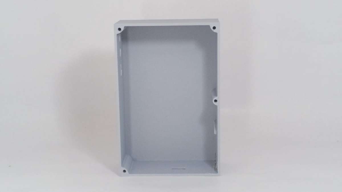
"Both the housing and cover were 3D printed in light gray on a Bambu Lab A1 . Parts came out strong, precise, and professional-looking — giving the Naveye Body a robust build with visual consistency between the Lid and Body design."
- Parts: Body (base), Lid (with braille "Naveye" embossed)
- Body
- Lid
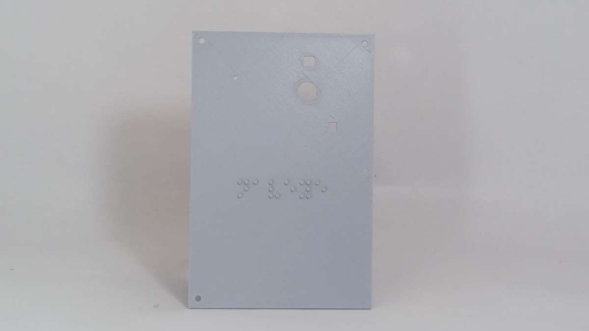
3d print
"Both the housing and cover were 3D printed in light gray on a Bambu Lab A1 . Parts came out strong, precise, and professional-looking — giving the Naveye Body a robust build with visual consistency between the Lid and Body design."
3D Prints File
- Naveye Lid STL: download here
Naveye Body STL: download here
Step 1
.jpeg)
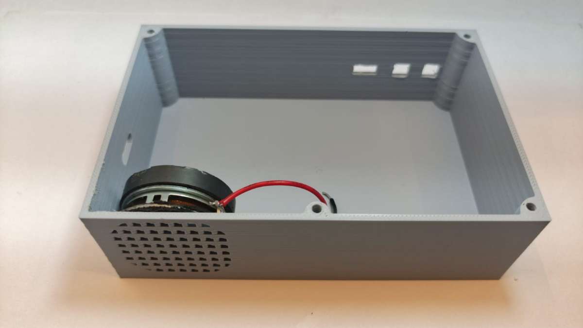
- Take the Naveye body and the 4Ω 3W speaker.
- Place the speaker into the body, ensuring correct orientation so it aligns properly with the speaker grille
.jpeg)
Step 2
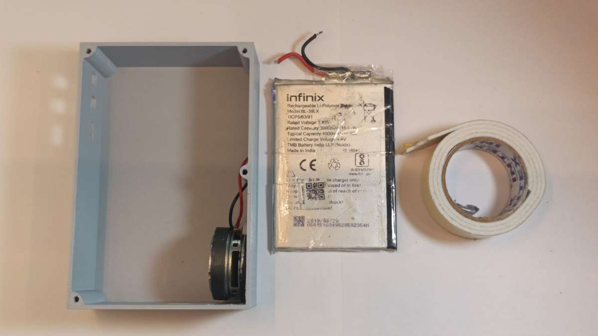
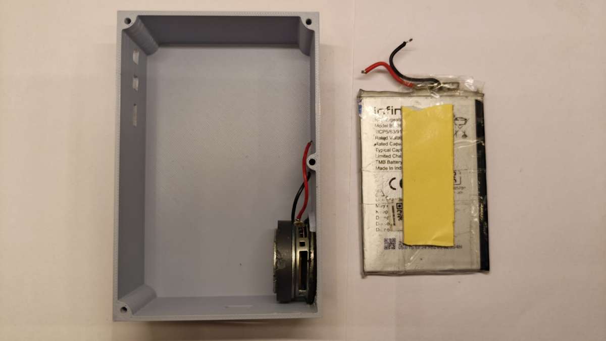
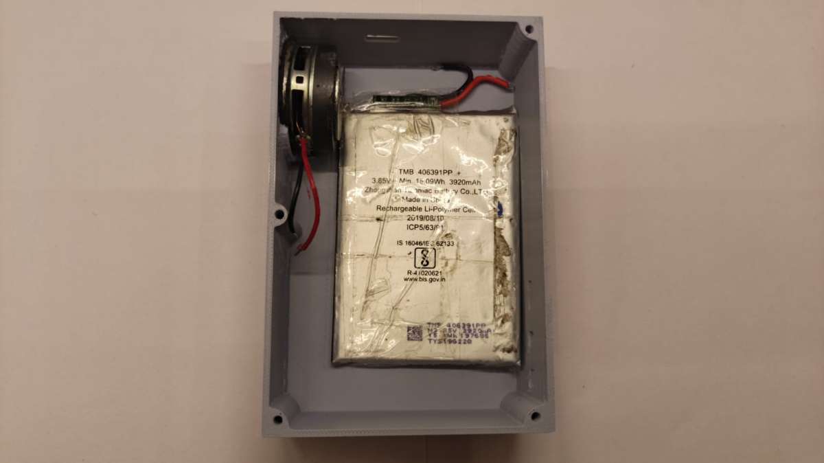
- Take battery and double-sided tape
- Cut a small strip of tape (match battery footprint, avoid overhang)
- Apply tape to battery's flat back face
- Peel off protective backing
- Press battery into Body cavity, positive/negative terminals facing correct connector side
- Press firmly for 5-10s for tape adhesion
Step 3
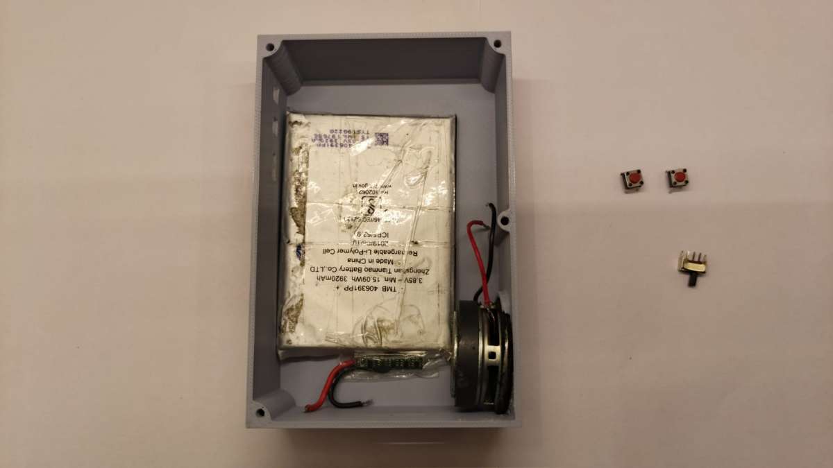
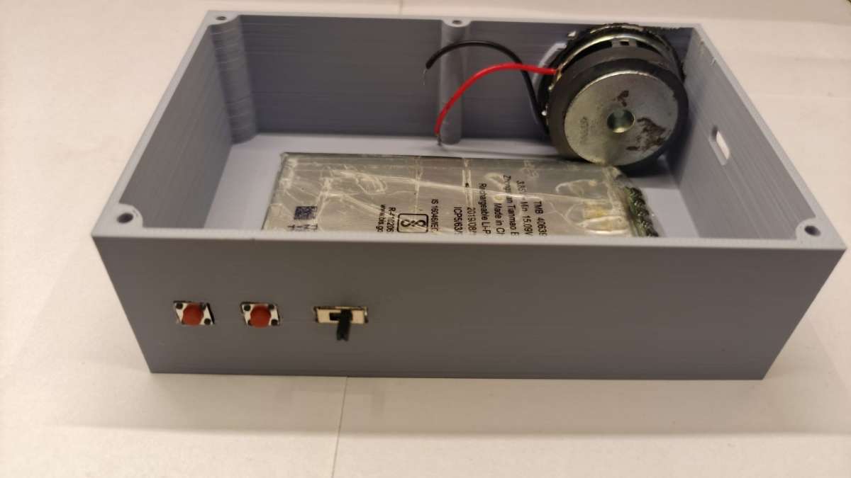
- 2× tactile switches + slide switch → seat into Body cutouts
- Tactile switches flush, centered, no tilt
- Slide switch flush, lever moves freely, not proud/recessed
.jpeg)
Step 4
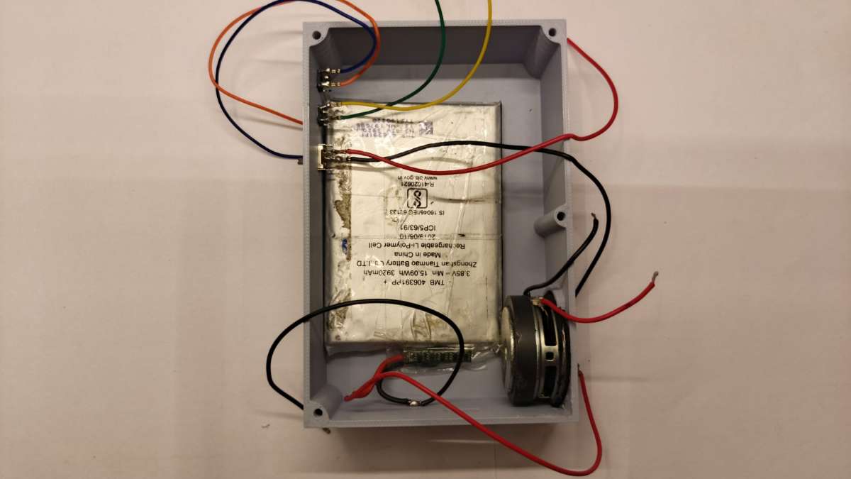
- Solder wire leads to tactile/slide switch terminals
Step 5
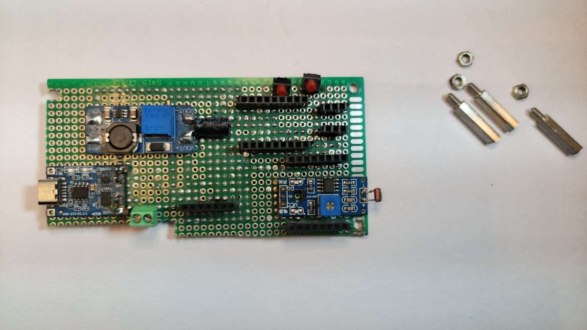
- Take circuit board + M3×15mm hex standoffs (×3)
- Screw standoffs into 3 mounting holes on Body
.jpeg)
Step 6
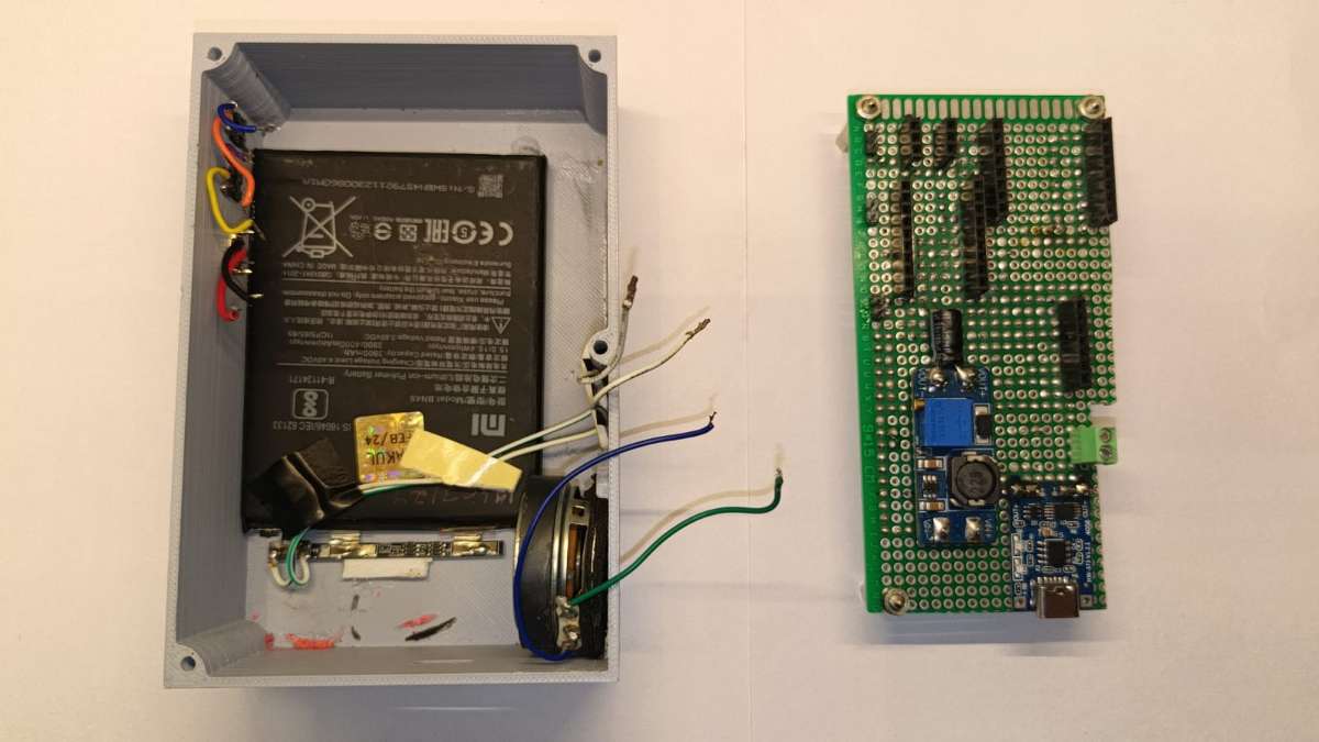
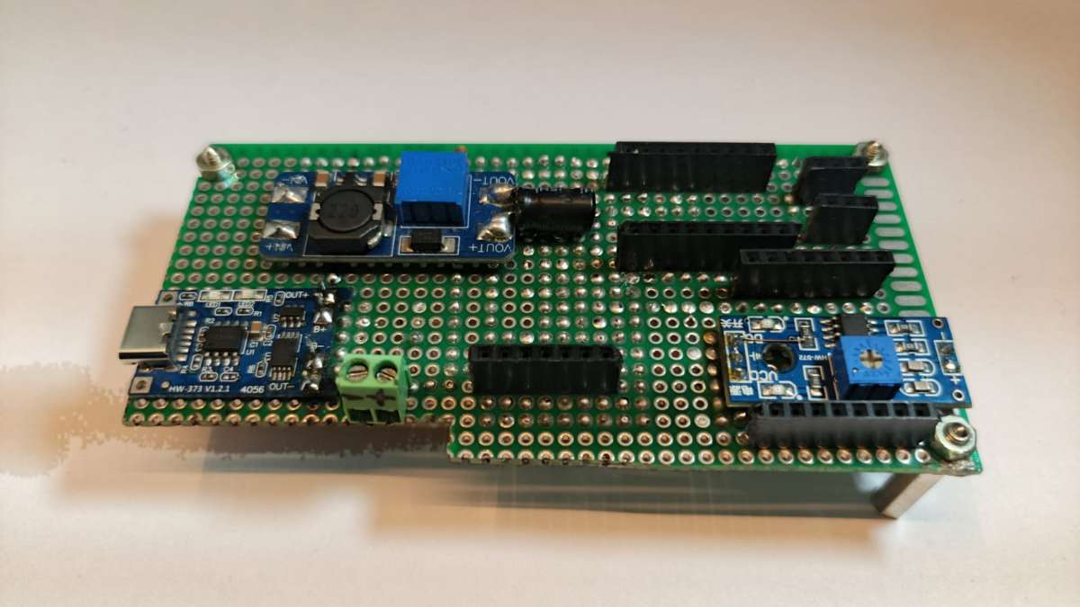
- Place circuit board onto standoffs, align mounting holes
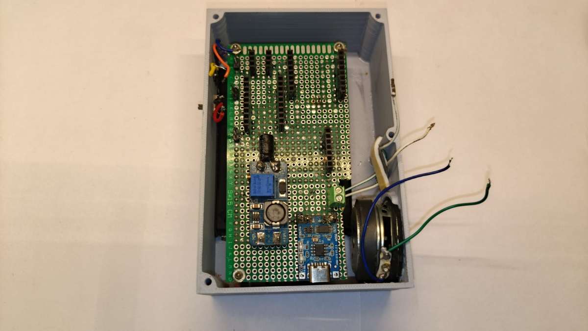
- Secure with M3 standoffs
- Solder button leads to designated pads
- Solder speaker leads (+/-) to amp output pads
- Connect battery to TP4056 input, verify polarity
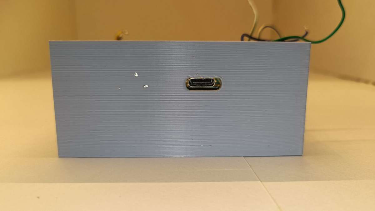
- Confirm USB-C port aligns correctly with Body's USB-C cutout before final seating
Step 7
.jpeg)
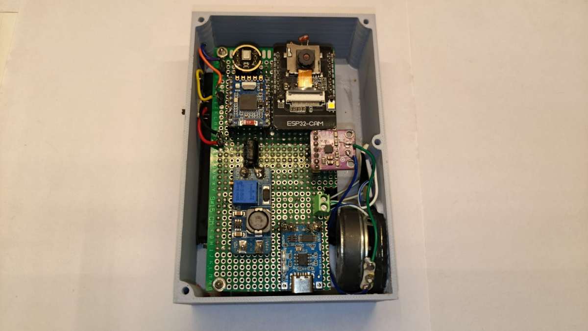
- Place all the main components (ESP32-S3-Tiny, Max98357a, INMP441, ESP32cam) onto the circuit board, making sure each one is seated with the correct pin orientation before securing.
STEP 8
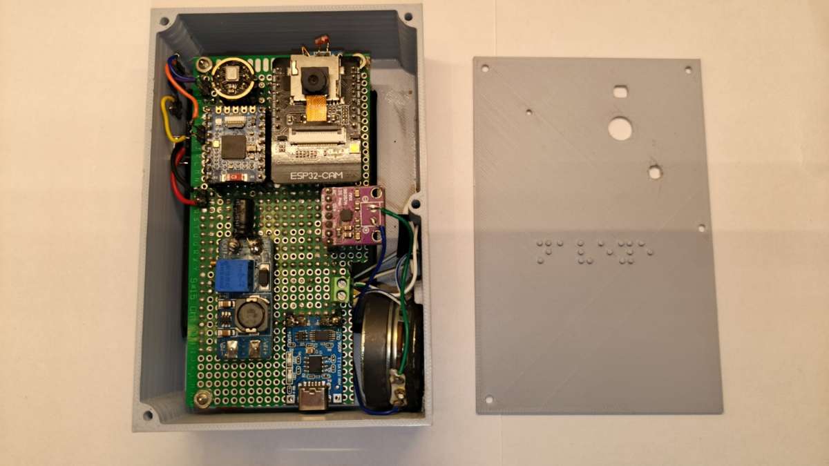
- Take Lid and Body
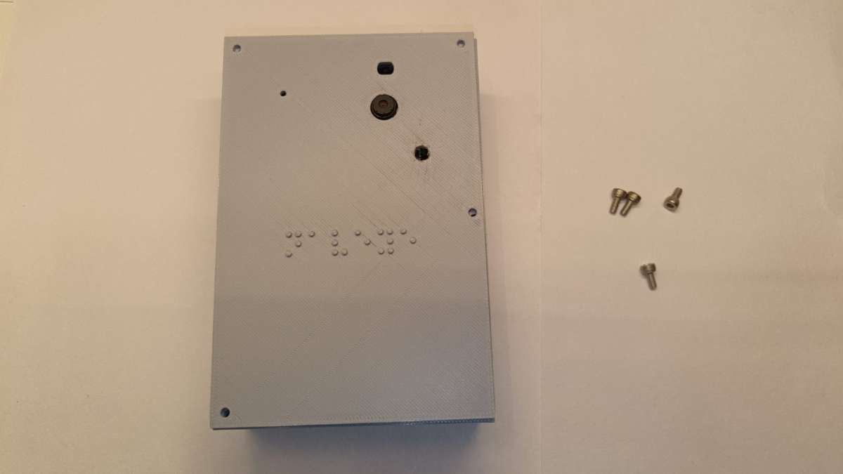
- Place Lid onto Body, ensure perfect alignment with mounting holes
- Take M3×6mm screws
- Screw into all Lid-Body mounting holes to secure
.jpeg)
.jpeg)
How it work