
Aim and Importance of the Project:
The primary aim of the ExpEYES AI Safety Bot in Industry 4.0 project is to develop a smart industrial safety monitoring system that enhances worker safety and machine protection in automated environments. Modern industries increasingly rely on high-speed machinery such as conveyor belts, robotic arms, drilling machines and motor-driven equipment. Without proper safety mechanisms, these systems can pose significant risks to human operators and nearby personnel.
This project uses an ultrasonic sensor to continuously monitor the surrounding area for the presence of humans or obstacles. When an object is detected within a predefined safety distance, the system automatically stops the motor, activates an audible alarm and provides visual warnings through LEDs. Once the area becomes safe, normal operation resumes automatically.
The project demonstrates the practical application of embedded systems, sensors, automation and Industry 4.0 concepts for improving workplace safety. It provides a low-cost and effective solution for reducing industrial accidents, preventing machine damage, minimizing downtime and ensuring safer interaction between humans and machines.
Furthermore, the proposed system can be extended for deployment in smart factories, automated production lines, warehouse robots, industrial safety monitoring systems, autonomous mobile robots and other Industry 4.0 applications. The project also highlights the importance of technology-driven safety solutions in modern industrial environments and promotes awareness of intelligent automation for accident prevention and operational efficiency.
1. Construction of the Project:
This project is explained step by step using both the ExpEYES kit and the Arduino UNO platform, allowing users to implement the system based on the available hardware. Both implementations follow the same working principle; however, only the pin connections differ between the PIC24-based ExpEYES kit and the Arduino UNO.
For detailed information regarding the ExpEYES 17 kit, including datasheets, user manuals, software downloads, purchasing details, and pin configurations, refer to: https://csparkresearch.in/expeyes17/. For Arduino UNO documentation and resources, visit: https://www.arduino.cc/.
This document describes how these platforms are utilized to design an AI Smart Bot for Industry 4.0 applications.
Components Required:
First, the required components must be collected as listed below.
| Component | Purpose |
| ExpEYES Kit / Arduino UNO | Main controller and interface |
| Ultrasonic Sensor (HC-SR04 / HSO4) | Human/object detection |
| DC Motor | Industrial machine simulation |
| NPN Transistor (2N3904) | Motor switching/control |
| Diode | Protection against back EMF from motor |
| Red LED | Danger indication |
| Green LED | Safe indication |
| Buzzer | Alarm sound |
| Resistors | Current limiting |
| Connecting wires | Circuit connections |
| Power supply | Circuit operation |
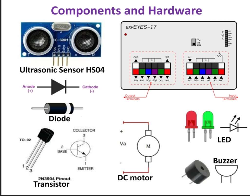
The symbols and images of each component are shown below to avoid confusion during selection and placement in the circuit.
Pin connections:
After selecting the required components, they are interfaced with the MCU kit to enable communication and proper system operation. The table below specifies the pin configuration used to connect each component to the corresponding interface pins.
| ExpEYES Pin | Arduino UNO Pins | Connected Device | Function |
| SQ2 & IN2 | D6 & D7 | Ultrasonic sensor output | Human/Object detection input |
| SQ1 | D8 | Buzzer | Alarm output |
| OD1 | D4 | Transistor base → DC Motor | Motor ON/OFF control |
| PV1 | D13 | Red LED | Danger indication |
| PV2 | D12 | Green LED | Safe indication |
Circuit Design and Construction:
The ExpEYES kit provides an easy-to-use interface with built-in connectors, making hardware connections simple and user-friendly. In this project, sensors and actuators such as the ultrasonic distance sensor, red and green LEDs, buzzer, and DC motor are interfaced with the ExpEYES kit as shown in the figures below. For clear identification, the connections are highlighted using different colors in the images.
| .png) |
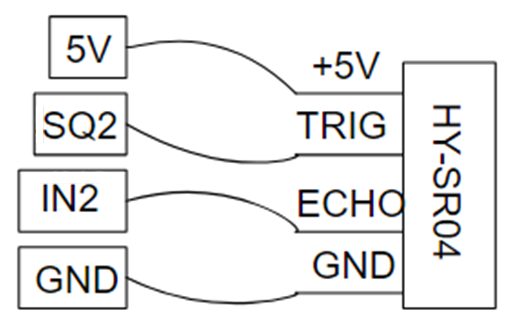
In the above figure, the SQ2 output pin is used to generate the trigger signal for the ultrasonic sensor, while the echo pulse is received through the IN2 input pin. Different colored male-to-female jumper wires (purple, yellow, green, and blue) are used to interface the distance sensor module with the PIC24-based ExpEYES kit. The distance is calculated based on the time difference between the transmitted ultrasonic pulse and the received echo signal. A predefined threshold value is used to trigger safety actions such as activating the buzzer, controlling DC motor operation (START/STOP), and switching LED indicators (ON/OFF). * In the Arduino UNO implementation, digital pins D6 and D7 are used for the trigger and echo connections of the ultrasonic distance sensor respectively. | |
 | .png) |
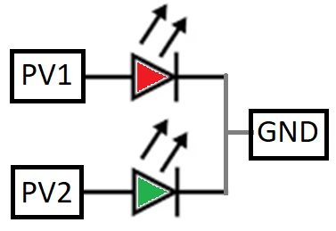
In the above figure, the connections of the RED and GREEN LEDs are shown. The RED LED is connected to the PV1 output pin through a 100 Ω series resistor and is used to indicate a danger or STOP condition. The GREEN LED is connected to the PV2 output pin through a 100 Ω series resistor and indicates a safe or START condition. The PV1 and PV2 pins are configured in the program to output either 5V or 3.3V as required. Based on the threshold value detected by the ultrasonic distance sensor, the LEDs are switched accordingly to provide visual alerts. * In the Arduino UNO implementation, digital pins D13 and D12 are used to control the RED and GREEN LEDs respectively, and are programmed using the Arduino IDE. | |
 | .png) |
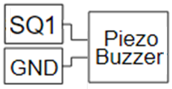
In the above circuit, the piezo buzzer is used to generate an audible siren for alerting or cautioning when a person or object approaches the system. The SQ1 output pin is used to produce a pulsed, variable-frequency signal that drives the buzzer. The SQ1 output is connected to the positive terminal of the buzzer, while the negative terminal is connected to ground. The siren is activated or deactivated based on the threshold value set by the ultrasonic distance sensor. * In the Arduino UNO implementation, digital pin D8 is used to generate the siren signal and control the buzzer operation. | |
 | .png) |
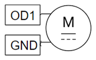
The DC motor is interfaced with the ExpEYES kit through a transistor-based driver circuit to protect the controller from high current. The OD1 output pin is used to control the DC motor, and it is connected to the base of a 2N transistor through a 100 Ω series resistor. The motor is connected to the collector terminal, while the emitter is grounded. A flyback diode is connected in parallel with the motor to protect the circuit from back EMF generated during switching. The transistor operates as a switch and is controlled by the OD1 signal, which is enabled or disabled based on the distance threshold detected by the ultrasonic sensor. * In the Arduino UNO implementation, digital pin D4 is used to drive the DC motor through a similar transistor-based switching circuit, enabling ON/OFF control based on sensor input. | |
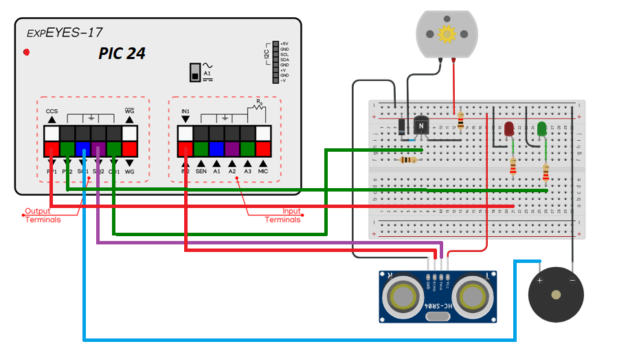
The final circuit connection using the PIC24-based ExpEYES 17 kit is shown in the diagram below for the implementation of the AI Smart Bot in Industry 4.0.
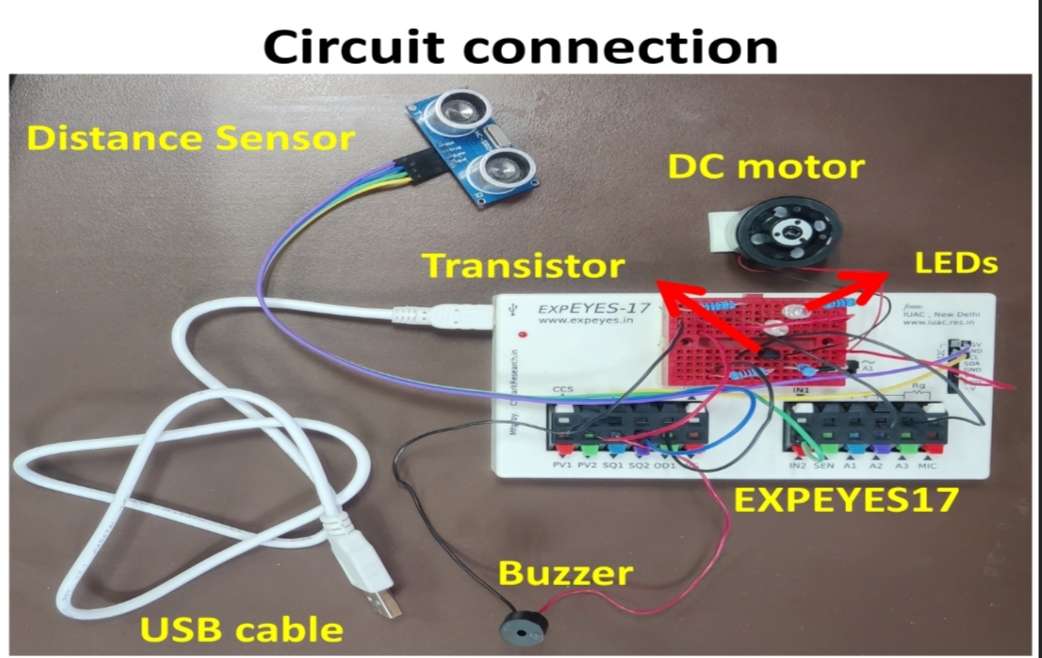
The physical connections of the complete circuit using all components on the ExpEYES kit are shown in the figure below.
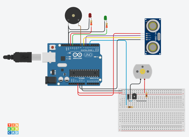
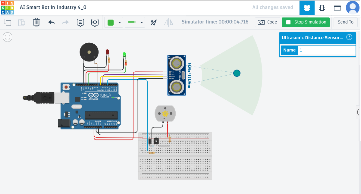
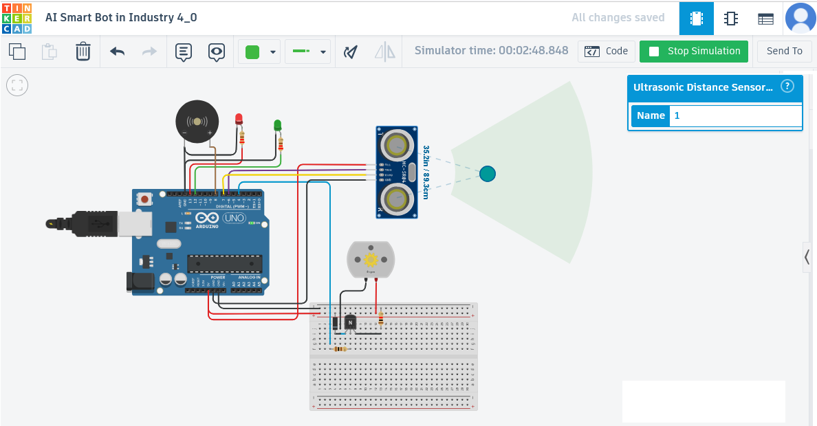
The AI Smart Bot for Industry 4.0 can also be implemented using the Arduino UNO kit. The circuit diagram is designed using Tinkercad, and the simulation screenshots are shown below, demonstrating system behavior when the obstacle distance is above and below the 90 cm threshold.
TEST and Simulation:
When the measured distance is greater than the 90 cm threshold defined in the program, the motor is turned ON and the green LED is activated, indicating a safe operating condition.
When the measured distance falls below the 90 cm threshold defined in the program, the motor is turned OFF, the buzzer siren is activated, and the red LED is turned ON to indicate a danger condition.
The video demonstration of the Arduino UNO simulation is shown below. The circuit design and simulation can be created using tools such as Tinkercad and Fritzing for better visualization and validation of the system.
2. Programming
Flow Chart and Python code:
The flowchart illustrates the control process of the system using the ExpEYES kit, showing how sensor inputs are processed to make intelligent safety decisions and control the connected actuators.
	Start System
		↓
Read Ultrasonic Sensor
		↓
Human/object Detected?

		Stop Motor	 ←←←←←←  YES
   Turn ON Red LED
Turn OFF Green LED
   Activate Buzzer

NO →→→→→→   Start Motor
			Turn ON Green LED
			Turn OFF Red LED
			Stop Buzzer
		↓
Repeat Continuously
The Python program used to control the bot using the ExpEYES kit is given below. It utilizes appropriate libraries to interface with the hardware and implement the safety monitoring and control functions.
#####.  Python Code. ####

import eyes17.eyes
import time
p = eyes17.eyes.open()

THRESHOLD = 90

print("= OBSTACLE DETECTION SYSTEM STARTED =")

def siren():
    for f in range(800, 2500, 150):
        p.set_sqr1(f)
        time.sleep(0.03)

    for f in range(2500, 800, -150):
        p.set_sqr1(f)
        time.sleep(0.03)

while True:
    try:
        distance = p.sr04_distance()

        if distance is None:
            print("Sensor error")
            p.set_state(OD1=0)
            p.set_pv1(3)
            p.set_pv2(0)
            p.set_sqr1(0)
            time.sleep(1)
            continue
        print("Distance:", distance, "cm")

        if distance <= THRESHOLD:
            print("Obstacle Detected")
            p.set_state(OD1=0)
            p.set_pv1(3)
            p.set_pv2(0)
            siren()

        else:
            print("Safe Distance")
            p.set_state(OD1=1)
            p.set_pv1(0)
            p.set_pv2(3)
            p.set_sqr1(0)

        time.sleep(0.3)

    except Exception as e:
        print("Error:", e)
        p.set_state(OD1=0)
        p.set_pv1(3)
        p.set_pv2(0)
        p.set_sqr1(0)
        time.sleep(1)
Below code is for Arduino UNO: The following Arduino code can be used when an Arduino UNO board is available as the controller platform. It performs the same safety monitoring and control functions as the ExpEYES-based implementation, including obstacle detection, motor control, LED indication, and alarm activation.
#define BUZZER_PIN 8
#define RED_LED    13
#define GREEN_LED  12
#define MOTOR_PIN  4
#define TRIG_PIN   6
#define ECHO_PIN   7

const int THRESHOLD = 90;   // cm

void setup() {
  Serial.begin(9600);
  pinMode(BUZZER_PIN, OUTPUT);
  pinMode(RED_LED, OUTPUT);
  pinMode(GREEN_LED, OUTPUT);
  pinMode(MOTOR_PIN, OUTPUT);
  pinMode(TRIG_PIN, OUTPUT);
  pinMode(ECHO_PIN, INPUT);
  digitalWrite(BUZZER_PIN, LOW);
  Serial.println("= OBSTACLE DETECTION SYSTEM STARTED =");
}

float getDistance() {
  digitalWrite(TRIG_PIN, LOW);
  delayMicroseconds(2);
  digitalWrite(TRIG_PIN, HIGH);
  delayMicroseconds(10);
  digitalWrite(TRIG_PIN, LOW);
  long duration = pulseIn(ECHO_PIN, HIGH, 30000);
  if (duration == 0)
    return -1;
  float distance = duration * 0.0343 / 2.0;
  return distance;
}

void siren() {
  for (int f = 800; f < 2500; f += 150) {
    tone(BUZZER_PIN, f);
    delay(30);
  }
  for (int f = 2500; f > 800; f -= 150) {
    tone(BUZZER_PIN, f);
    delay(30);
  }
}

void loop() {
  float distance = getDistance();
  if (distance < 0) {
    Serial.println("Sensor Error");
    digitalWrite(RED_LED, HIGH);
    digitalWrite(GREEN_LED, LOW);
    digitalWrite(MOTOR_PIN, LOW);
    noTone(BUZZER_PIN);
    delay(1000);
    return;
  }
  Serial.print("Distance: ");
  Serial.print(distance);
  Serial.println(" cm");
  if (distance <= THRESHOLD) {
    Serial.println("Obstacle Detected");
    digitalWrite(RED_LED, HIGH);
    digitalWrite(GREEN_LED, LOW);

    // Stop motor
    digitalWrite(MOTOR_PIN, LOW);
    siren();
  } else {
    Serial.println("Safe Distance");
    digitalWrite(RED_LED, LOW);
    digitalWrite(GREEN_LED, HIGH);

    // Run motor
    digitalWrite(MOTOR_PIN, HIGH);
    noTone(BUZZER_PIN);
  }
  delay(300);
}
3. Execution and Operation
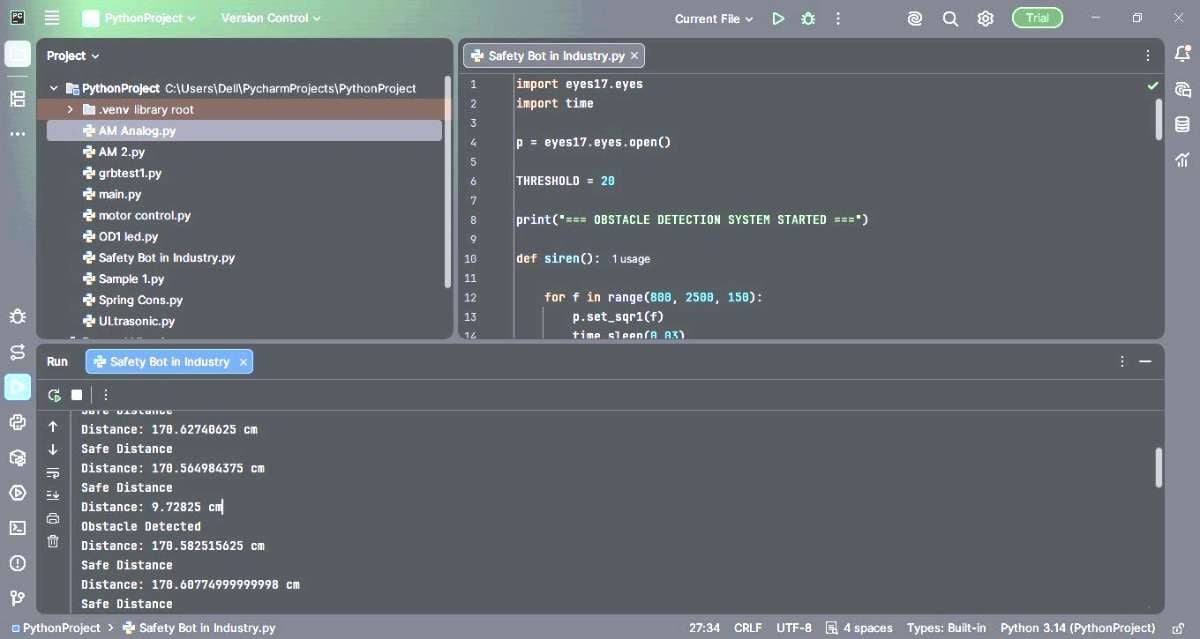
Python coding on Pycharm IDE:
In this project, the Python program was developed and executed using the PyCharm IDE. The code communicates with the PIC24-based ExpEYES kit to acquire data from the ultrasonic sensor and control the connected devices, including the DC motor, LEDs, and buzzer. PyCharm provided a convenient development environment for writing, testing, and debugging the Python application used in the industrial safety monitoring system.
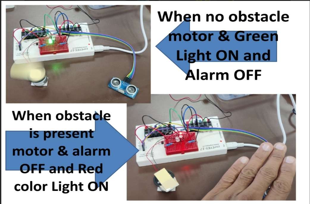
The figure below demonstrates the operation of the industrial safety system. As a human or object approaches the predefined safety zone, the ultrasonic sensor detects the obstacle and triggers the control system to stop the DC motor, activate the alarm with Buzzer, and provide visual warning indications with RED & GREEN LED's. This safety mechanism helps reduce the risk of workplace accidents and prevents collisions between personnel and moving industrial equipment.
4. Video Demo:
The final video demonstrates the operation of the AI-based Smart Safety Bot for Industry 4.0 applications. The system continuously monitors the surrounding area, detects human or object presence, and automatically performs safety actions to prevent accidents and ensure safe human-machine interaction. This prototype represents a simplified model of the intelligent safety systems used in modern industrial robots and automated production environments.
Conclusion:
The ExpEYES Safety Bot successfully demonstrates an industrial safety monitoring system using the ExpEYES kit and an ultrasonic sensor. The system continuously monitors the surrounding environment, detects the presence of humans or objects and automatically performs safety actions such as stopping the DC motor, activating an audible alarm with Buzzer and providing visual indications through RED and GREEN LEDs. Once the obstacle is removed and the area becomes safe, the system automatically resumes normal operation.
This project highlights the practical application of embedded systems, sensors and automation technologies in industrial safety and robotics. It provides a simple, low-cost, and effective solution for enhancing worker safety, reducing the risk of accidents and preventing damage to industrial equipment. The implementation also demonstrates how Industry 4.0 concepts can be integrated into safety-critical environments to enable safer interaction between humans and machines.
Although the current project is a basic prototype, it has significant potential for further development and real-world deployment. Future enhancements may include the integration of artificial intelligence, computer vision, IoT-based remote monitoring, predictive safety analytics, and machine learning algorithms for advanced hazard detection. Similar safety systems can be applied in autonomous robots, drones, Advanced Driver Assistance Systems (ADAS), self-cleaning robots, agricultural robots (Agri-bots), smart warehouses and automated manufacturing facilities.
Overall, the project serves as an effective demonstration of how intelligent automation can contribute to creating safer, smarter, and more efficient industrial environments.