.jpg)
Introduction
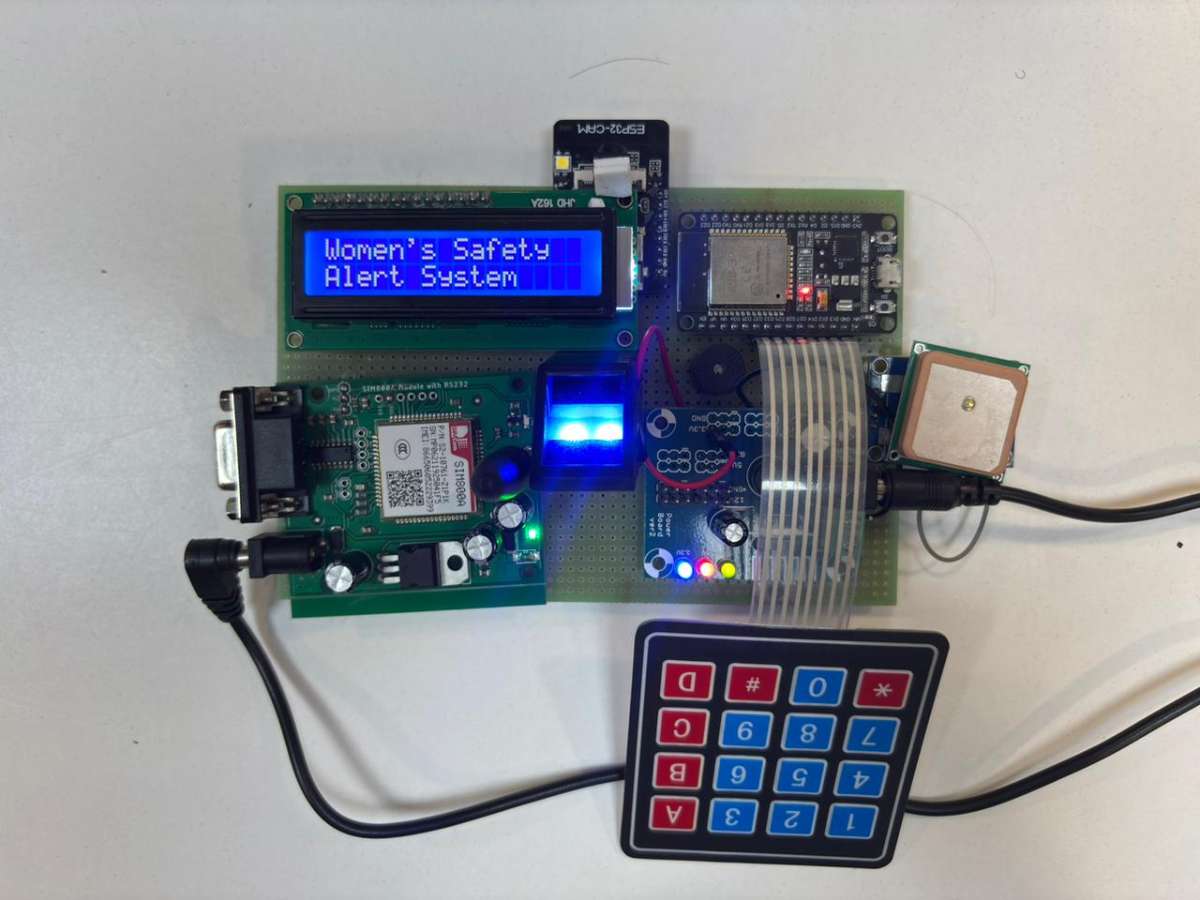
Women face various safety challenges while traveling alone, especially on two-wheelers. In emergency situations, it may be difficult to contact family members or authorities quickly. This project provides a smart safety solution that combines biometric authentication, GPS tracking, GSM communication, image capture, and emergency alert features into a single system.
The system is built using an ESP32 microcontroller and is designed to improve the safety of women riders by providing quick assistance during emergencies.
Objectives
- Provide secure access using fingerprint authentication.
- Send emergency alerts to predefined contacts.
- Share real-time GPS location during emergencies.
- Capture images using ESP32-CAM for evidence.
- Generate a loud alarm using a buzzer.
- Display system status through an LCD.
- Verify users using OTP through a keypad.
Components Used
- ESP32 Development Board
- ESP32-CAM Module
- SIM800A GSM Module
- NEO-6M GPS Module
- AS608 Fingerprint Sensor
- 16x2 LCD Display
- 4x4 Matrix Keypad
- Active Buzzer
- Prototype PCB (Perf Board)
- Connecting Wires
DC Power Supply
.png)
Working Principle
Step 1: System Initialization
When power is supplied, the ESP32 initializes all connected modules including GSM, GPS, LCD, Fingerprint Sensor, Keypad, Buzzer, and ESP32-CAM.
Step 2: User Authentication
The user places a finger on the fingerprint sensor.
- If the fingerprint matches a stored fingerprint, access is granted.
- If the fingerprint does not match, access is denied.
Step 3: Emergency Activation
In an emergency situation, the user can activate the safety mode.
The ESP32 immediately performs multiple actions:
- Activates the buzzer.
- Reads GPS coordinates.
- Captures an image using ESP32-CAM.
- Generates an OTP.
- Sends SMS alerts through the GSM module.
Step 4: GPS Tracking
The GPS module continuously provides latitude and longitude coordinates.
The location is included in the SMS alert so family members can track the rider's position.
Step 5: Image Capture
The ESP32-CAM captures images of the surrounding environment.
These images can help identify people or events related to the emergency.
Step 6: SMS Alert
The GSM module sends an emergency message containing:
- Alert notification
- GPS location
- OTP information
The message is sent to predefined emergency contacts.
Step 7: OTP Verification
The keypad allows the user to enter the OTP.
The system verifies the OTP before allowing specific actions such as disabling the emergency mode.
Circuit Diagram
The circuit diagram illustrates the interconnection between the ESP32 controller and all peripheral modules used in the Smart Women's Safety and Emergency Alert System. The ESP32 serves as the central controller and interfaces with the GSM module, GPS module, ESP32-CAM, AS608 fingerprint sensor, 4x4 keypad, 16x2 LCD display, and buzzer. During an emergency, the system captures location data, generates alerts, captures images, and sends notifications to predefined contacts, ensuring enhanced safety and security for women riders.
.png)
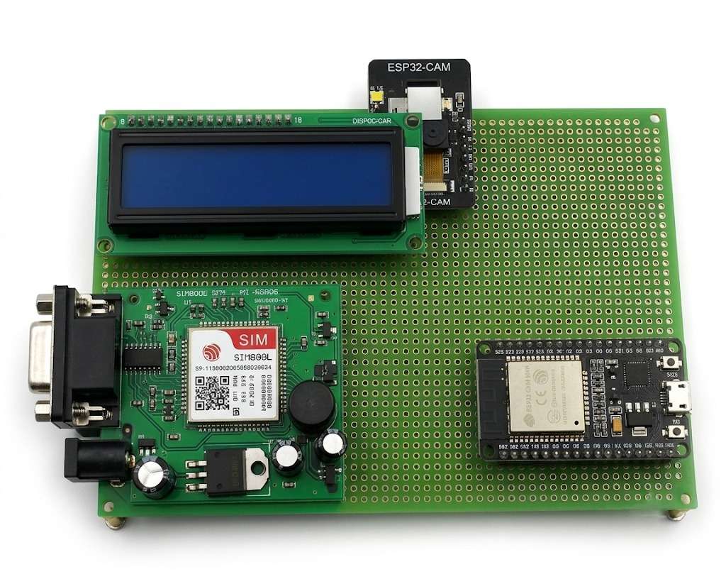
Hardware Assembly
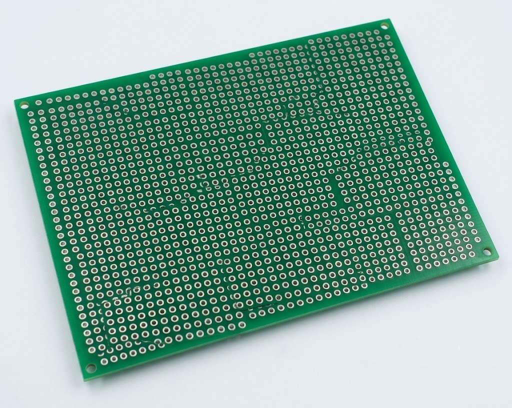
Step 1: Hardware Base Preparation
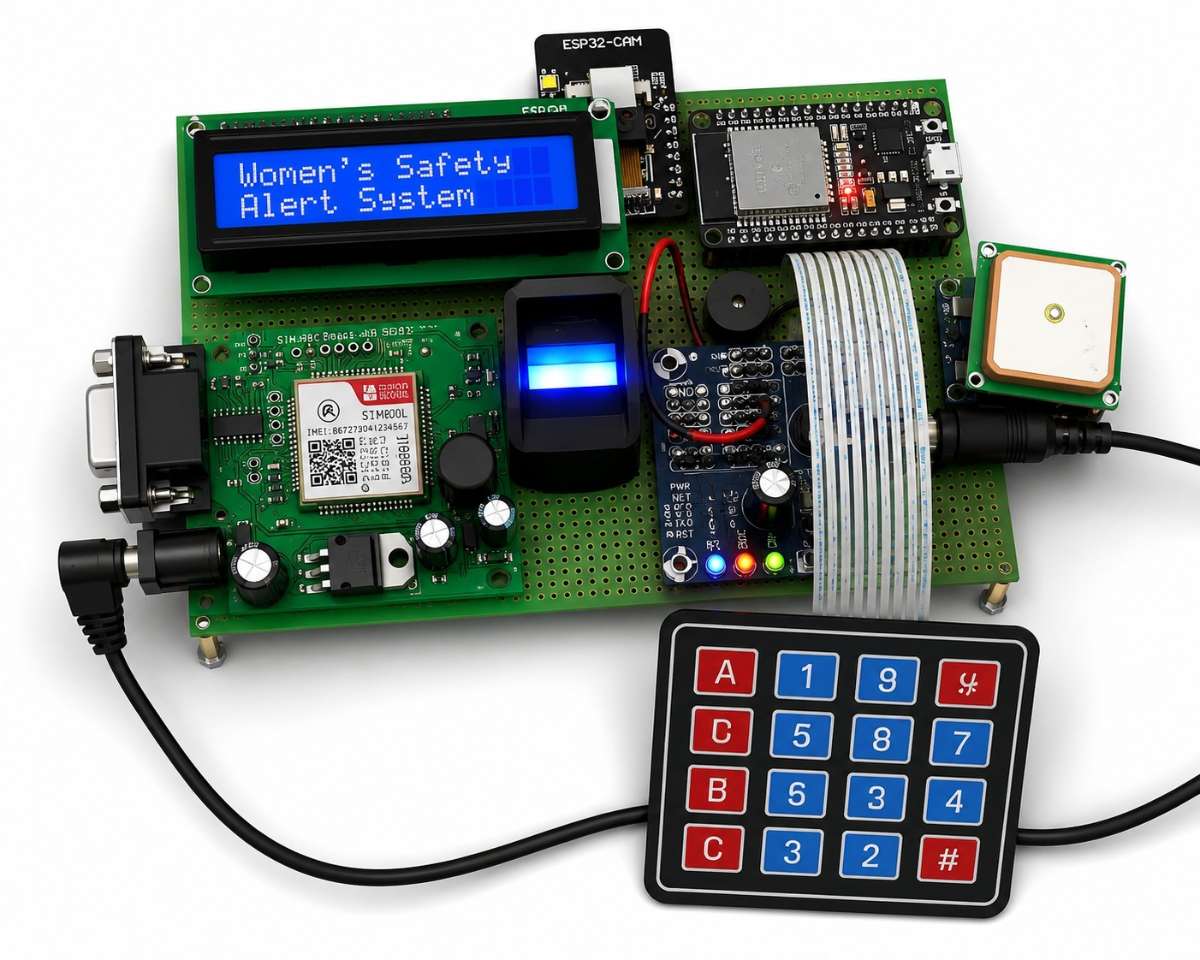
The prototype PCB serves as the foundation for assembling the Smart Women's Safety and Emergency Alert System. All electronic components including the ESP32, GSM module, GPS module, fingerprint sensor, ESP32-CAM, LCD display, keypad, and buzzer are mounted and interconnected on this board.
The prototype PCB provides a flexible platform for creating custom circuits without the need for a fabricated PCB. Components are securely soldered onto the board, ensuring reliable electrical connections and easy integration of all modules used in the project.
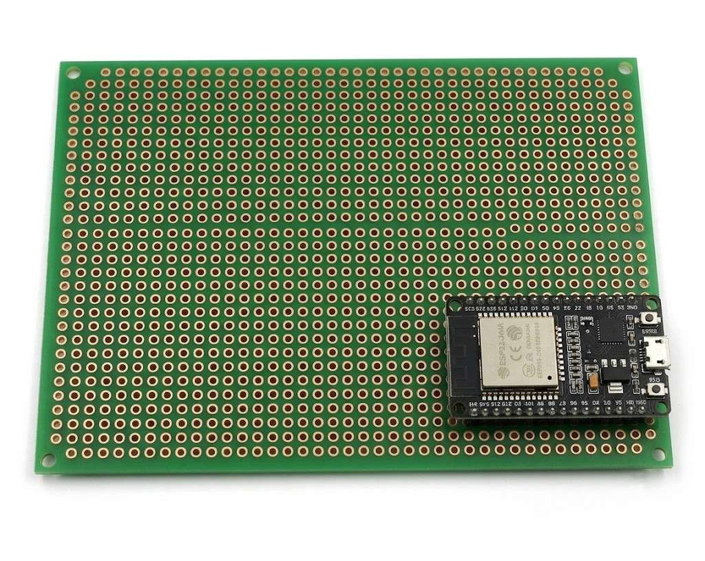
Step 2: ESP32 Development Board Installation
The ESP32 Development Board is mounted on the prototype PCB and serves as the main controller of the Smart Women's Safety and Emergency Alert System. It coordinates communication between all connected modules, including the GPS module, GSM module, fingerprint sensor, ESP32-CAM, keypad, LCD display, and buzzer.
The ESP32 processes user inputs, manages emergency alerts, acquires GPS location data, controls image capture through the ESP32-CAM, and handles OTP verification. Due to its built-in Wi-Fi and Bluetooth capabilities, low power consumption, and high processing performance, the ESP32 is an ideal controller for IoT-based safety applications.
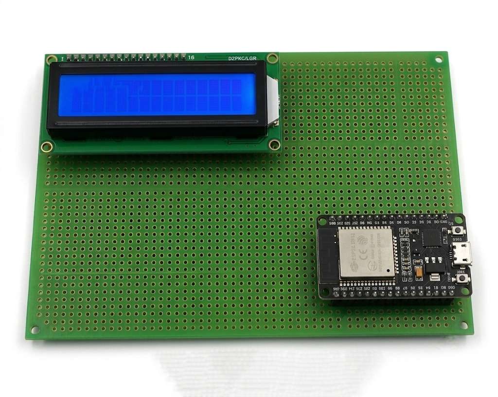
Step 3: LCD Display Integration
The 16x2 LCD display is mounted on the prototype PCB to provide real-time system information to the user. The display is used to show system status, fingerprint authentication messages, OTP verification prompts, GPS status, and emergency alert notifications.
The LCD enhances user interaction by providing clear visual feedback during system operation. It helps users understand the current state of the system without requiring additional devices.
Step 4: ESP32-CAM Integration
The ESP32-CAM module is added to the prototype PCB to enable image capture during emergency situations. This module allows the system to record visual evidence and monitor the surrounding environment when the emergency mode is activated.
The ESP32-CAM works alongside the ESP32 controller and captures images whenever an emergency alert is triggered. The captured images can be stored or transmitted for further analysis, enhancing the overall safety and security of the rider.
.jpeg)
Step 5: GSM Module Integration
The SIM800L GSM module is integrated into the prototype PCB to enable wireless communication during emergency situations. This module is responsible for sending SMS alerts and OTP verification messages to predefined emergency contacts.
When the emergency mode is activated, the ESP32 communicates with the GSM module to transmit important information such as emergency alerts, OTP codes, and location details obtained from the GPS module. This ensures that family members or guardians are immediately informed about the user's situation.
Step 6: Fingerprint Sensor Integration
The AS608 Fingerprint Sensor is integrated into the prototype PCB to provide secure user authentication. This biometric module ensures that only authorized users can access and operate the Smart Women's Safety and Emergency Alert System.
The fingerprint sensor captures and verifies the user's fingerprint before granting access to system functions. During operation, the ESP32 communicates with the fingerprint module to authenticate users and enhance the overall security of the system.
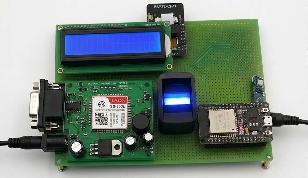
Step 7: Buzzer Integration and System Alert Testing
The active buzzer is integrated into the Smart Women's Safety and Emergency Alert System to provide an immediate audible alert during emergency situations. When the emergency mode is activated, the ESP32 triggers the buzzer to generate a loud alarm, helping attract nearby attention and alert people in the surrounding area.
At this stage, the major hardware components including the ESP32, GSM module, ESP32-CAM, fingerprint sensor, LCD display, and buzzer are assembled and tested together on the prototype PCB.

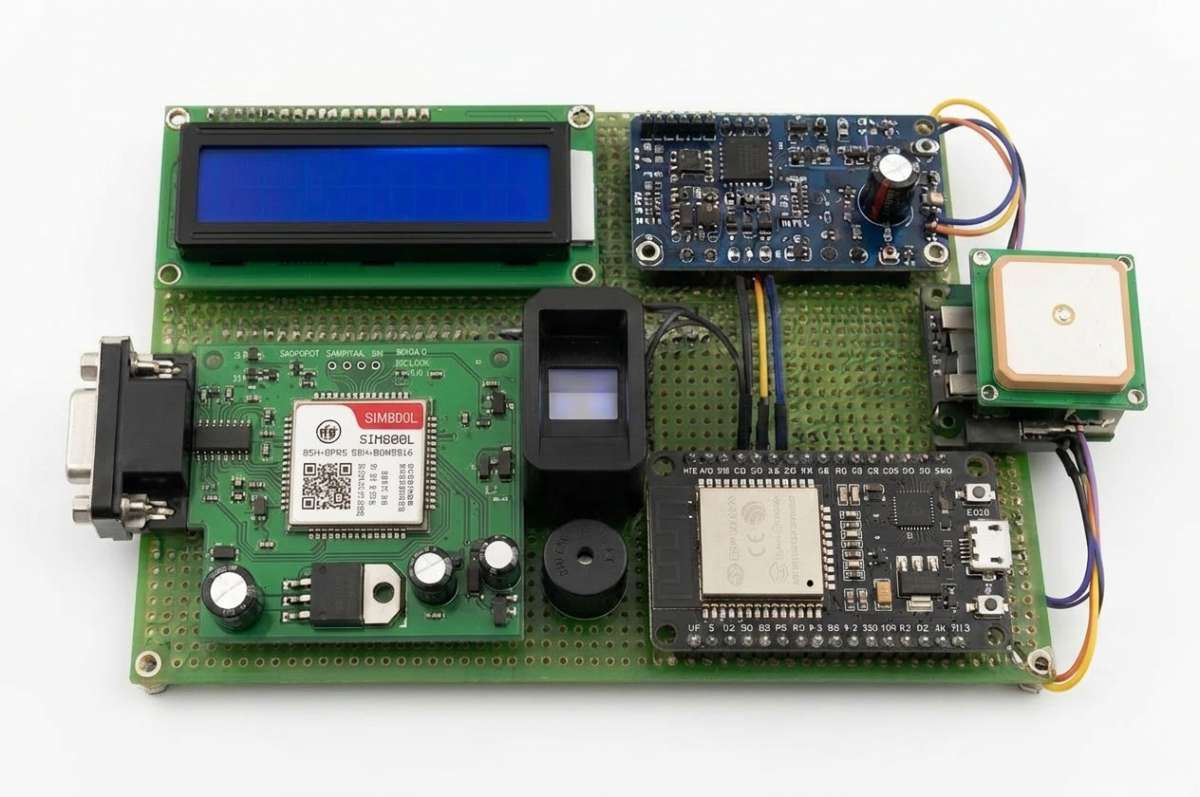
Step 8: Major Module Integration
After integrating all individual modules, the complete Smart Women's Safety and Emergency Alert System is assembled on the prototype PCB. The system now consists of the ESP32 controller, GSM module, GPS module, fingerprint sensor, LCD display, buzzer, and supporting circuitry working together as a single embedded safety solution.
At this stage, all modules are securely mounted and interconnected according to the circuit design. The assembled hardware is ready for software deployment, functional testing, and real-world operation.
Step 8: Matrix Keypad Integration
The 4x4 Matrix Keypad is integrated into the Smart Women's Safety and Emergency Alert System to provide user input functionality. The keypad allows users to enter passwords, OTPs, emergency commands, and system configuration settings.
The ESP32 continuously scans the keypad rows and columns to detect key presses. During emergency situations, the keypad can be used for OTP verification and secure access to system functions.
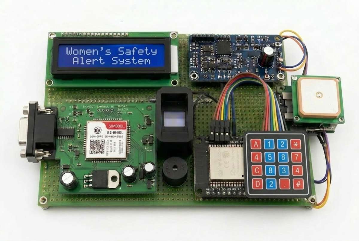
Step 10: Final Hardware Setup
The final hardware prototype integrates all modules into a single working system. The ESP32 acts as the central controller, coordinating communication between the GSM module, GPS module, fingerprint sensor, ESP32-CAM, LCD display, keypad, and buzzer. The assembled system is ready for software deployment, testing, and real-world operation.
Software Implementation
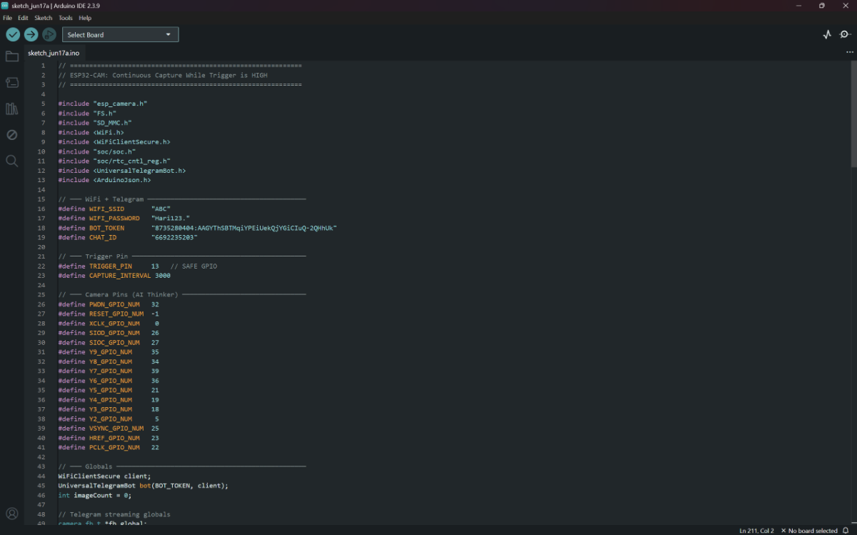
Step 1: ESP32-CAM Programming
The ESP32-CAM module is programmed using Arduino IDE to capture images during emergency situations. When an emergency trigger is activated, the ESP32-CAM captures photographs and stores or transmits them through the communication system. The camera module helps collect visual evidence and enhances the overall effectiveness of the Smart Women's Safety and Emergency Alert System.
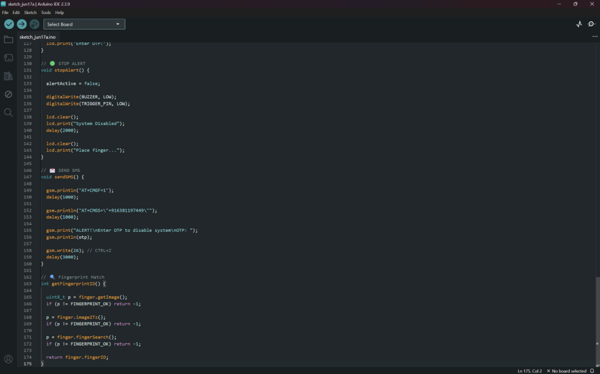
Step 19: ESP32 Main Controller Programming
The ESP32 main controller is programmed using the Arduino IDE. The firmware manages communication between all hardware modules including the GSM module, GPS module, fingerprint sensor, LCD display, matrix keypad, buzzer, and ESP32-CAM. The ESP32 continuously monitors user authentication, emergency events, location tracking, OTP verification, and alert generation.
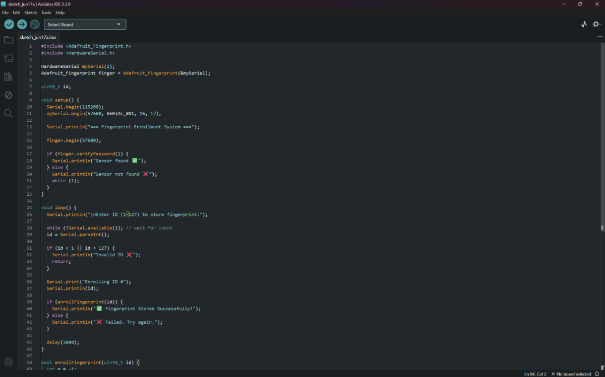
Step 20: Fingerprint Enrollment Program
Before using the system, authorized users must register their fingerprints in the fingerprint sensor memory. A dedicated enrollment program is uploaded to the ESP32 to capture and store fingerprint templates. These templates are later used for authentication during system operation.
Real-World Implementation and Testing
Step 1: Device Installation Inside Scooter
The ESP32 controller is installed inside the scooter and connected to the vehicle power supply. It acts as the central processing unit of the Smart Women's Safety and Emergency Alert System. The controller continuously monitors all connected modules and coordinates communication between the GPS, GSM, fingerprint sensor, LCD, keypad, and ESP32-CAM.
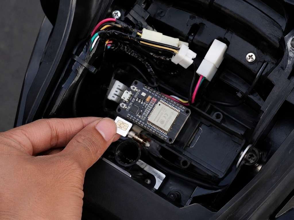
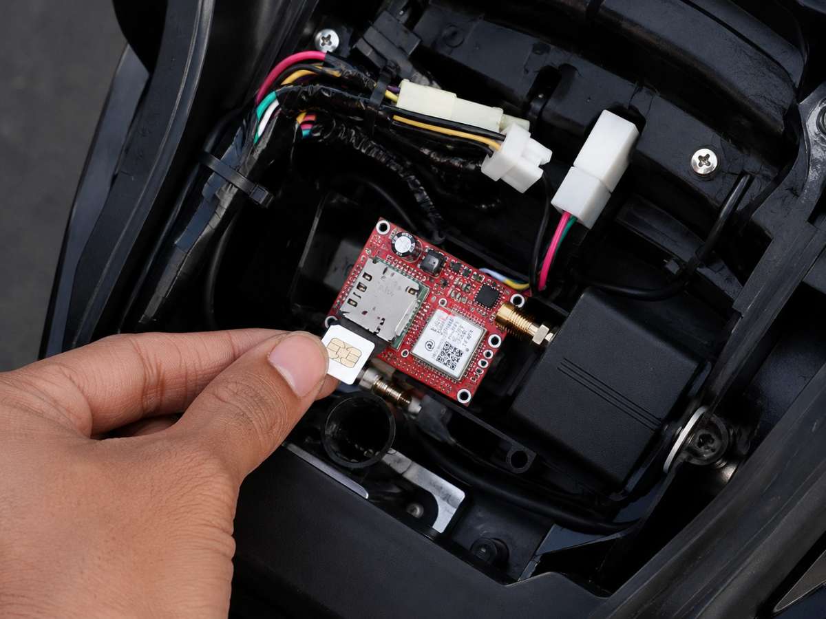
Step 2: GSM Module SIM Card Installation
A SIM card is inserted into the GSM module to enable cellular communication. The GSM module is responsible for sending emergency SMS alerts, OTP messages, and location information to predefined emergency contacts whenever the safety mode is activated.
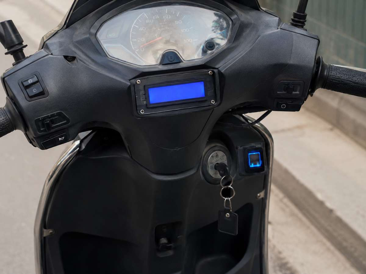
Step 3: LCD and Fingerprint System Mounted on Scooter
The LCD display and fingerprint sensor are mounted on the scooter dashboard for easy user access. The LCD provides system status messages, while the fingerprint sensor ensures that only authorized users can access and operate the vehicle.
Step 4: User Authentication Through Fingerprint Verification
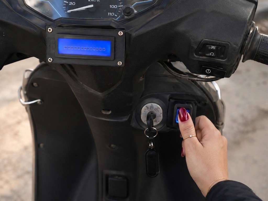
Before starting the vehicle, the rider places a finger on the fingerprint sensor. The system compares the scanned fingerprint with the stored fingerprint database. If a match is found, the user is authenticated and system access is granted.
Step 5: Emergency Alert SMS Generation
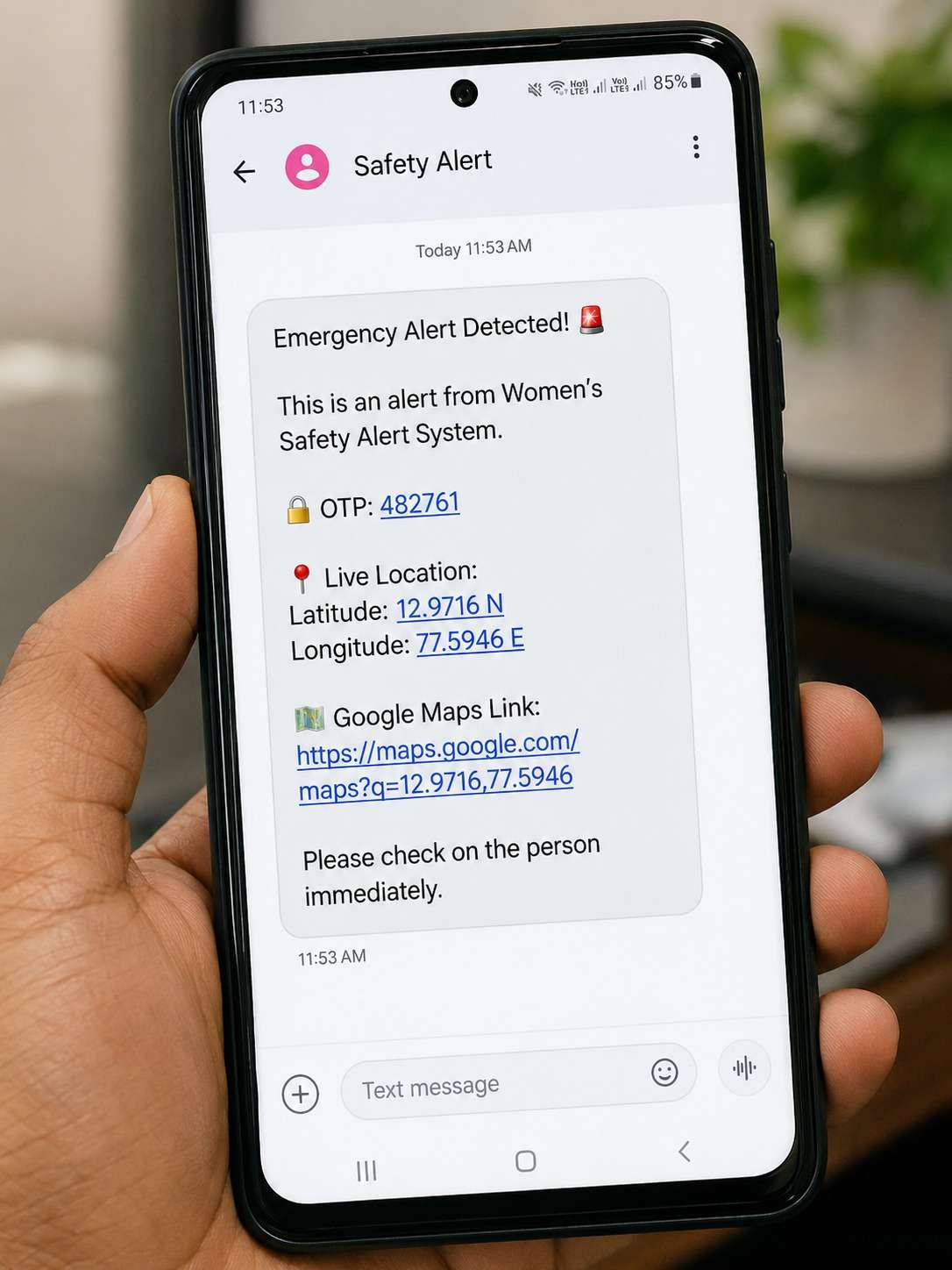
When an emergency situation is detected, the ESP32 immediately activates the GSM module and sends an emergency SMS. The message contains an alert notification, OTP, GPS coordinates, and a Google Maps link to the user's current location.
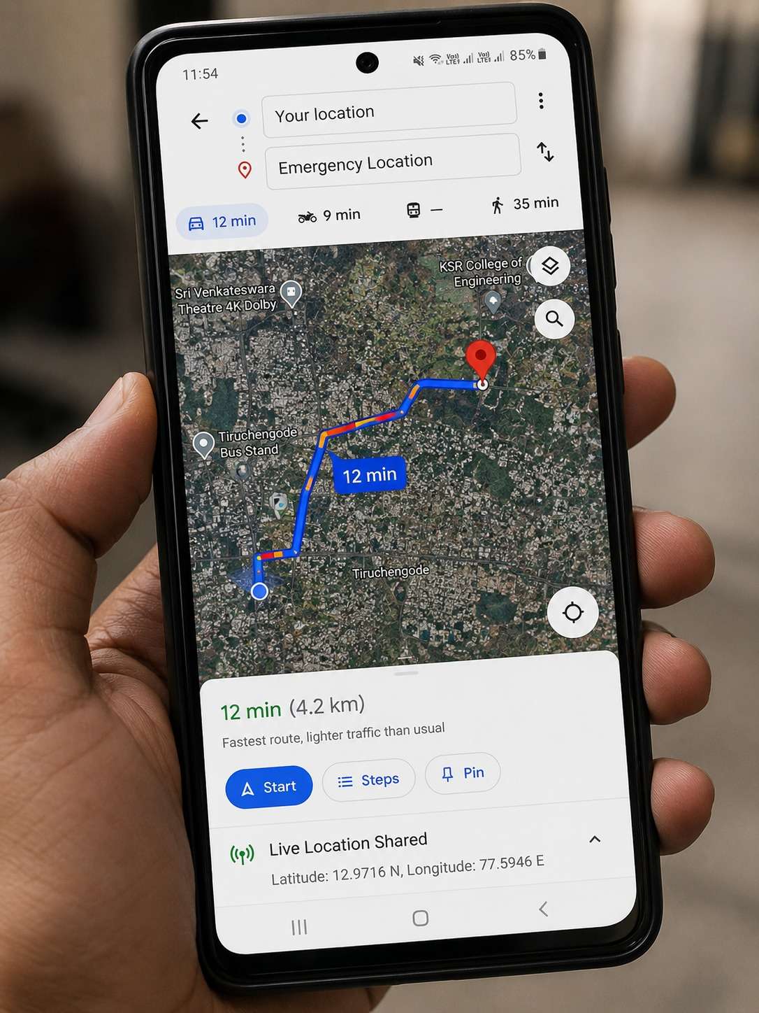
Step 6: Live GPS Location Tracking
The GPS module continuously tracks the rider's location. Emergency contacts can open the received Google Maps link and view the exact location of the rider in real time, enabling quick assistance and response.
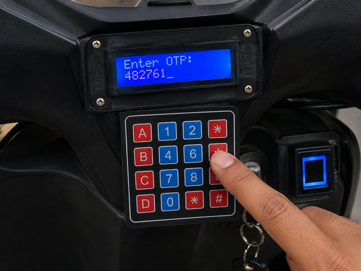
Step 7: OTP Verification Using Matrix Keypad
The emergency SMS contains a One-Time Password (OTP). The authorized user enters this OTP through the 4×4 matrix keypad. The ESP32 verifies the entered OTP before allowing access to protected functions such as disabling emergency mode or unlocking the vehicle.
Advantages
- Fast emergency response.
- Real-time GPS location tracking.
- Secure fingerprint authentication.
- OTP-based user verification.
- Emergency SMS alert system.
- Image capture using ESP32-CAM.
- User-friendly LCD display interface.
- Suitable for two-wheeler safety applications.
Applications
- Women's Safety Systems.
- Smart Vehicle Security.
- Personal Emergency Alert Devices.
- Two-Wheeler Tracking Systems.
- Student Safety Monitoring.
- Elderly Safety Assistance.
- IoT-Based Security Solutions.
Results
The Smart Women's Safety and Emergency Alert System was successfully designed and implemented using ESP32, GPS, GSM, fingerprint sensor, ESP32-CAM, LCD display, buzzer, and matrix keypad. The system successfully authenticated users through fingerprint verification, generated OTP-based verification, transmitted emergency SMS alerts with GPS location, and enabled real-time tracking through Google Maps. The prototype demonstrated reliable performance during testing and effectively improved user safety during emergency situations.
Future Enhancements
- Mobile application integration.
- Cloud-based data storage.
- Voice-activated emergency trigger.
- AI-based threat detection.
- Live video streaming using ESP32-CAM.
- Accident detection using sensors.
- Emergency calling feature.
- Battery backup support.
Conclusion
The Smart Women's Safety and Emergency Alert System for Two Wheelers provides an effective solution for enhancing rider safety during emergencies. By integrating fingerprint authentication, GPS tracking, GSM communication, OTP verification, ESP32-CAM image capture, and real-time alerts, the system ensures quick response and improved security. The successful implementation and testing of the prototype demonstrate its potential for real-world deployment in modern safety applications.