Smart Earthing Monitoring System
"In large public areas like parking lots and railway stations, electrical pole lights are equipped with earthing systems for safety. However, if the earthing malfunctions or the earth resistance becomes too high, it can leave dangerous leakage current on the conductor — posing a serious risk of electric shock to the public. Manually inspecting every earthing point requires huge manpower and is time consuming."
"The Smart Earthing Monitoring System addresses this challenge by continuously and automatically monitoring two critical parameters — leakage current and earth resistance — in real time. The end result is a smart, sensor-based system that instantly detects any abnormality, triggers a buzzer and LED alert on-site, and simultaneously sends a notification to the online monitoring dashboard, enabling maintenance staff to identify and resolve the issue quickly — before it becomes a threat to human life."
Step 1: Hardware Components
Before starting the assembly, ensure you have all the necessary components ready.
| Components | Quantity | Photo |
| ESP32 Wroom 32 | 1 | 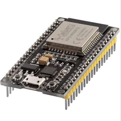 |
| ACS712 Current Sensor | 2 | 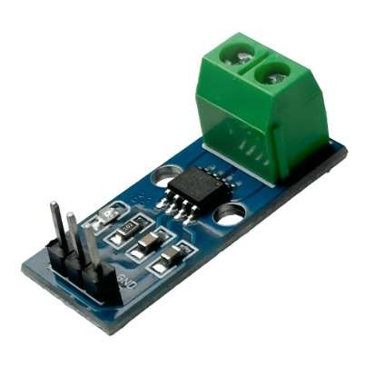 |
| ZMPT101B Voltage Sensor | 1 | 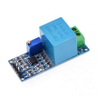 |
| Soil Moisture Sensor | 1 | 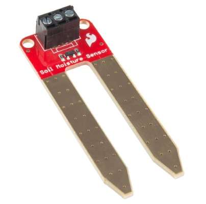 |
| 16x2 LCD with I2C Module | 1 | 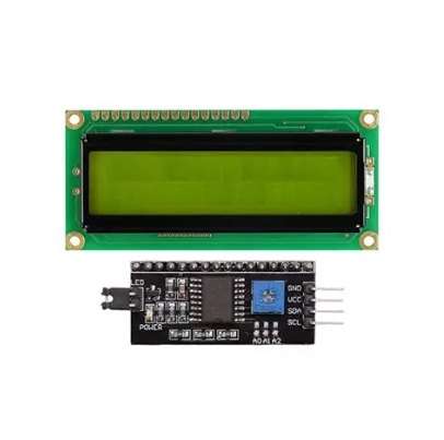 |
| 5V Buzzer | 1 | 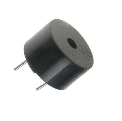 |
| Red LED's | 3 | 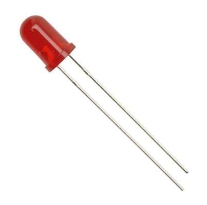 |
| Perf board | 1 | .jpeg) |
| 330ohm Resistor | 3 | 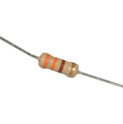 |
| Jumper Wires | as required | 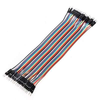 |
| Bulb and Bulb holder | 2 each | 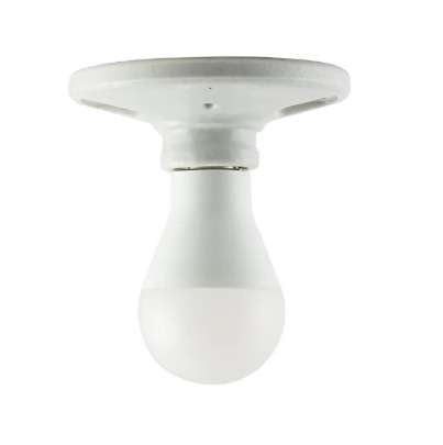 |
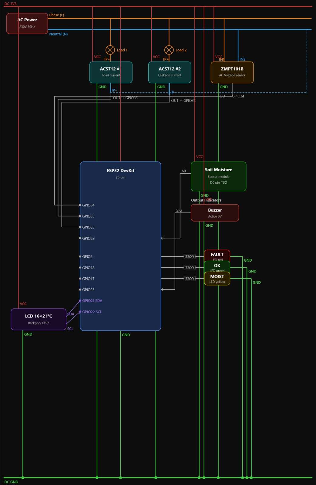
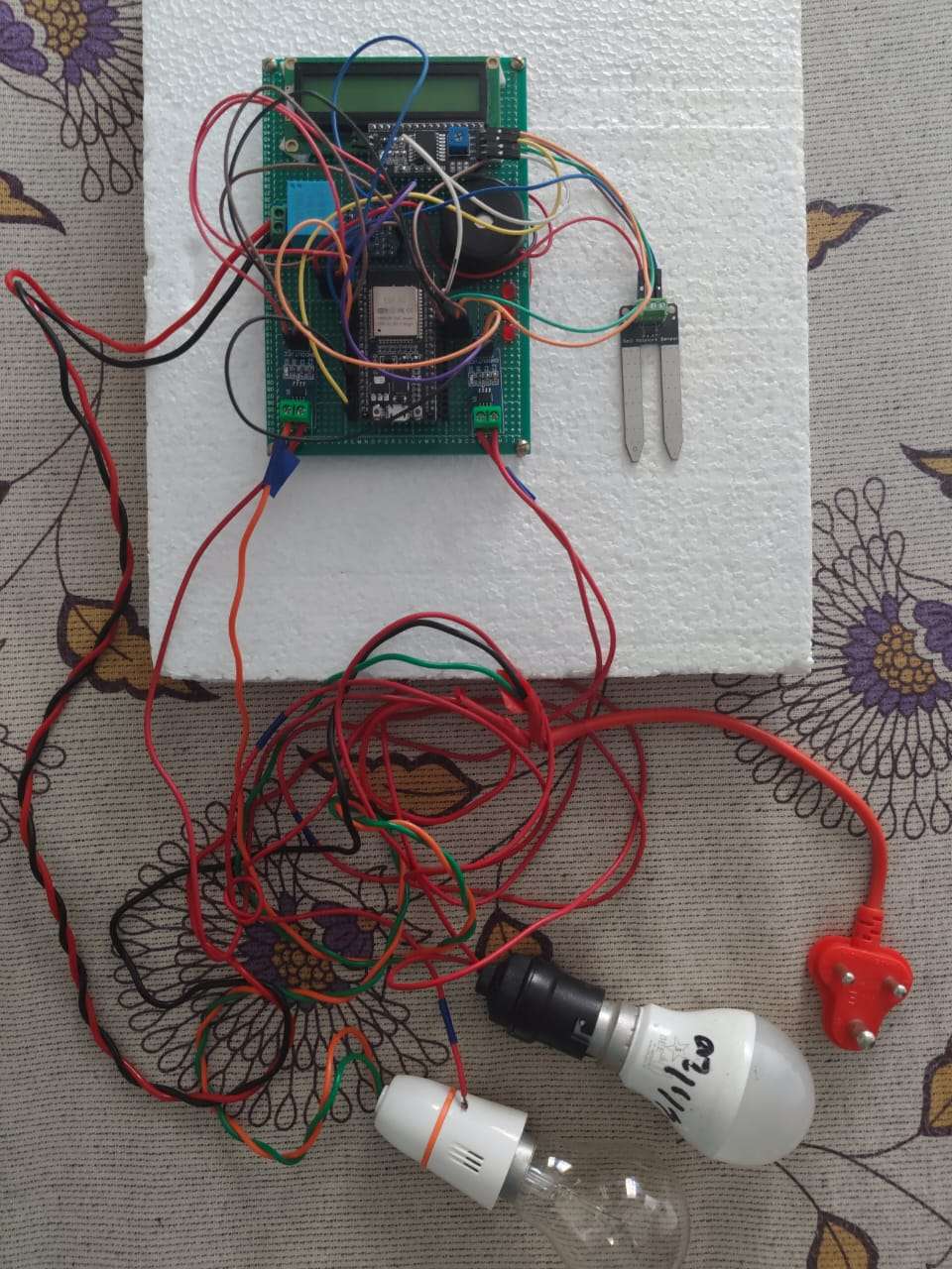
Step 2: Microcontroller & Power Setup
- Fix the ESP32 board securely on the perf board.
- Then solder the ESP32 board with perf board.
- Ensure the ESP32 is securely mounted so the micro-USB port is easily accessible to power up the ESP32 and programming
Step 3: Sensor Wiring & Pin Mapping
Sensors:
- ZMPT101B (Voltage): VCC to 3.3V, GND to GND, OUT to GPIO 34
- ACS712 (Load Current): VCC to 3.3V, GND to GND, OUT to GPIO 35
- ACS712 (Leakage Current): VCC to 3.3V, GND to GND, OUT to GPIO 33
- Soil Moisture Sensor: VCC to 3.3V, GND to GND, Analog OUT to GPIO 32
Display & Indicators:
- 16x2 LCD Display with I2C Module: VCC to 5V, GND to GND, SDA to GPIO 21, SCL to GPIO 22
- LED (Fault): Anode to GPIO 5 (via resistor)
- LED (OK): Anode to GPIO 18 (via resistor)
- LED (Moisture): Anode to GPIO 17 (via resistor)
- Active Buzzer: Positive terminal to GPIO 23
Safety Warning: When connecting the AC load to the ZMPT101B and ACS712 sensors, ensure all power is completely disconnected.

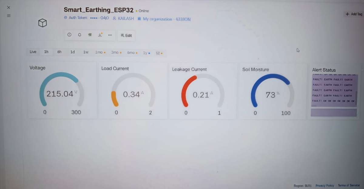
Step 4: Configuring the Blynk IoT Dashboard
Set up the cloud receiver, before uploading the code.
Log into the Blynk IoT and create a new Template named "Smart Earthing Monitoring System".
Go to Datastreams and create five Virtual Pins:
- V0 (Double): Line Voltage
- V1 (Double): Load Current
- V2 (Double): Leakage Current
- V3 (Integer): Moisture Percentage
- V4 (String): System Status
Build your Web Dashboard using three Gauges (for V0, V1, V2), one Level/Gauge (V3), and a Value Display (V4).
Copy your BLYNK_AUTH_TOKEN from the device info page.
Step 5: Uploading the code to the ESP32
- Open the Arduino IDE.
- Ensure you have the ESP32 Board Manager installed, along with the
BlynkandLiquidCrystal_I2Clibraries. - Paste the code into the IDE.
- Update the Wi-Fi credentials (
ssidandpassword) and paste your uniqueBLYNK_AUTH_TOKENat the top of the code. - Select your specific ESP32 board model from the Tools menu, choose the correct COM port, and click Upload.
#define BLYNK_TEMPLATE_ID "TMPL38Z--_573"
#define BLYNK_TEMPLATE_NAME "Smart Earthing Monitoring System"
#define BLYNK_PRINT Serial

#include <Wire.h>
#include <WiFi.h>
#include <BlynkSimpleEsp32.h>
#include <LiquidCrystal_I2C.h>

// ================= WIFI & BLYNK =================
char auth[] = "2Ip70ugs9wabVCnyFGyY5bVyYJ0BQ4jO";
const char* ssid = "ss";
const char* password = "12345678";

// ================= PIN DEFINITIONS =================
#define VOLTAGE_PIN        34   // ZMPT101B
#define LOAD_CURRENT_PIN   35   // ACS712 - Load current
#define LEAK_CURRENT_PIN   33   // ACS712 - Leakage current
#define MOISTURE_PIN       32

#define LED_FAULT     5
#define LED_OK        18
#define LED_MOISTURE  17
#define BUZZER        23

// ================= LCD =================
LiquidCrystal_I2C lcd(0x27, 16, 2);

// ================= CONSTANTS =================
#define ADC_MAX 4095.0
#define VREF 3.3
#define ACS_SENSITIVITY 0.100     // ACS712-20A (100 mV/A)
#define LOAD_CAL_FACTOR   0.111
#define LEAK_CAL_FACTOR   0.098

#define LEAKAGE_THRESHOLD 0.30     // 20 mA

#define MOISTURE_DRY 3300
#define MOISTURE_WET 1200

// ================= VARIABLES =================
float Vrms = 0;
float LoadIrms = 0;
float LeakIrms = 0;

float loadOffset = 0;
float leakOffset = 0;

int moistureValue = 0;
unsigned long lastRead = 0;
unsigned long leakStartTime = 0;
unsigned long lastLCD = 0;


// ================= SETUP =================
void setup() {
  Serial.begin(115200);

  analogReadResolution(12);
  analogSetAttenuation(ADC_11db);

  analogSetPinAttenuation(VOLTAGE_PIN, ADC_11db);
  analogSetPinAttenuation(LOAD_CURRENT_PIN, ADC_11db);
  analogSetPinAttenuation(LEAK_CURRENT_PIN, ADC_11db);
  analogSetPinAttenuation(MOISTURE_PIN, ADC_11db);

  pinMode(LED_FAULT, OUTPUT);
  pinMode(LED_OK, OUTPUT);
  pinMode(LED_MOISTURE, OUTPUT);
  pinMode(BUZZER, OUTPUT);

  Wire.begin(21, 22);
  lcd.init();
  lcd.backlight();

  lcd.setCursor(0,0);
  lcd.print("Smart Earthing");
  lcd.setCursor(0,1);
  lcd.print("Initializing...");
  delay(2000);
  lcd.clear();

  calibrateCurrentSensors();

  WiFi.begin(ssid, password);
  Blynk.config(auth);
  Blynk.connect();
}

// ================= LOOP =================
void loop() {
  Blynk.run();


  if (millis() - lastRead >= 1000) {
    lastRead = millis();

    readVoltage();
    readLoadCurrent();
    readLeakageCurrent();
    readMoisture();

if (LoadIrms < 0.05) {LeakIrms = 0.0;}


    if (millis() - lastLCD >= 1000) {
    lastLCD = millis();
    updateLCD();
}

    sendToBlynk();
    handleAlerts();
  }
}

// ================= VOLTAGE RMS =================
void readVoltage() {
  const int samples = 1000;
  float sumSq = 0;

  for (int i = 0; i < samples; i++) {
    float adc = analogRead(VOLTAGE_PIN);
    float voltage = (adc * VREF) / ADC_MAX;
    float ac = voltage - (VREF / 2.0);
    sumSq += ac * ac;
    delayMicroseconds(200);
  }

  float sensorVrms = sqrt(sumSq / samples);
  float VOLT_CAL = 645.71;   // Adjust with multimeter
  Vrms = sensorVrms * VOLT_CAL;
}

// ================= CALIBRATION =================
void calibrateCurrentSensors() {
  const int samples = 1500;
  long sumLoad = 0;
  long sumLeak = 0;

  Serial.println("Calibrating ACS712...");
  Serial.println("REMOVE ALL LOADS!");
  delay(4000);

  for (int i = 0; i < samples; i++) {
    sumLoad += analogRead(LOAD_CURRENT_PIN);
    sumLeak += analogRead(LEAK_CURRENT_PIN);
    delayMicroseconds(200);
  }

  loadOffset = (sumLoad / (float)samples) * VREF / ADC_MAX;
  leakOffset = (sumLeak / (float)samples) * VREF / ADC_MAX;

  Serial.print("Load Offset: ");
  Serial.println(loadOffset, 4);
  Serial.print("Leak Offset: ");
  Serial.println(leakOffset, 4);
}

// ================= LOAD CURRENT =================
void readLoadCurrent() {
  const int samples = 1000;
  float sumSq = 0;

  for (int i = 0; i < samples; i++) {
    float adc = analogRead(LOAD_CURRENT_PIN);
    float voltage = (adc * VREF) / ADC_MAX;
    float ac = voltage - loadOffset;
    float current = (ac / ACS_SENSITIVITY) * LOAD_CAL_FACTOR;
    sumSq += current * current;
    delayMicroseconds(200);
  }

  LoadIrms = sqrt(sumSq / samples);
  if (LoadIrms < 0.01) LoadIrms = 0.0;
}


void readLeakageCurrent() {

  // If no load is flowing, leakage must be zero
  if (LoadIrms < 0.05) {
    LeakIrms = 0.0;
    return;
  }

  const int samples = 1000;
  float sumSq = 0;

  for (int i = 0; i < samples; i++) {
    float adc = analogRead(LEAK_CURRENT_PIN);
    float voltage = (adc * VREF) / ADC_MAX;
    float ac = voltage - leakOffset;
    float current = (ac / ACS_SENSITIVITY) * LEAK_CAL_FACTOR;
    sumSq += current * current;
    delayMicroseconds(200);
  }

  LeakIrms = sqrt(sumSq / samples);

  // HARD clamp
  if (LeakIrms < 0.1) LeakIrms = 0.0;
}


// ================= MOISTURE =================
void readMoisture() {
  int raw = analogRead(MOISTURE_PIN);

  moistureValue = map(raw, MOISTURE_DRY, MOISTURE_WET, 100, 0);
  moistureValue = constrain(moistureValue, 0, 100);
}

// ================= LCD =================
void updateLCD() {
  lcd.clear();

  lcd.setCursor(0,0);
  lcd.print("L:");
  lcd.print(LoadIrms,2);
  lcd.print("A ");

  lcd.print("E:");
  lcd.print(LeakIrms,3);

  lcd.setCursor(0,1);
  lcd.print("Moist:");
  lcd.print(moistureValue);
  lcd.print("%");
}


// ================= BLYNK =================
void sendToBlynk() {
  Blynk.virtualWrite(V0, Vrms);
  Blynk.virtualWrite(V1, LoadIrms);
  Blynk.virtualWrite(V2, LeakIrms);
  Blynk.virtualWrite(V3, moistureValue);

  String alert = "OK";

  if (LeakIrms > LEAKAGE_THRESHOLD && LoadIrms > 0.1) {
    alert = "EARTH FAULT!";
  }else if (moistureValue < 30) {
    alert = "LOW MOISTURE";
  }

  Blynk.virtualWrite(V4, alert);
}

// ================= ALERTS =================
void handleAlerts() {
  digitalWrite(LED_OK, LOW);
  digitalWrite(LED_FAULT, LOW);
  digitalWrite(LED_MOISTURE, LOW);
  digitalWrite(BUZZER, LOW);

  // ---------- EARTH FAULT CONFIRMATION ----------
  if (LeakIrms > LEAKAGE_THRESHOLD && LoadIrms > 0.1) {

    if (leakStartTime == 0) {
      leakStartTime = millis();   // start timing
    }

    if (millis() - leakStartTime >= 3000) {
      // EARTH FAULT CONFIRMED
      digitalWrite(LED_FAULT, HIGH);
      digitalWrite(BUZZER, HIGH);
    }

  } else {
    leakStartTime = 0;   // reset timer
    digitalWrite(LED_OK, HIGH);
  }

  // ---------- MOISTURE ALERT ----------
  if (moistureValue < 30) {
    digitalWrite(LED_MOISTURE, HIGH);
    digitalWrite(BUZZER, HIGH);
  }
}
Step 6: Testing & Calibration
- Wait for the initialization to finish.
- Turn on your simulated streetlight load (the incandescent bulbs). The LCD and Blynk dashboard should immediately show a stable voltage and a normal load current.
- Test the Soil Sensor: Remove the moisture probe from the soil. The LED(LED_MOISTURE) should light up, the buzzer will sound, and the dashboard will warn "LOW MOISTURE".
- Test the Leakage Fault: Carefully introduce your bypass ground fault. The system will wait 3 seconds to verify the fault, then trigger the RED LED(LED_FAULT), the buzzer, and update the cloud status to "EARTH FAULT!".