



Introduction
My name is Kamal Deen, from Ghana, near Kumasi, where some communities still face limited access to healthcare due to poor road infrastructure.
In these areas, access to essential medical supplies such as insulin, first-aid kits, and basic medication can be slow and unreliable. During emergencies, these delays can become life-threatening.
Motivated by these challenges, this project explores how engineering and open-source hardware can provide a practical and scalable solution.
This work presents a medical delivery drone system designed to transport essential medical supplies quickly, safely, and reliably to underserved communities.
Project Overview
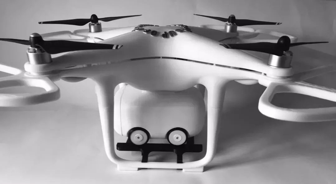
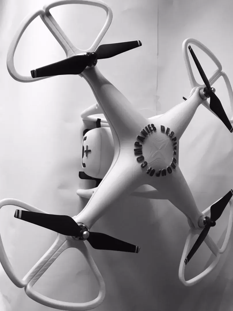
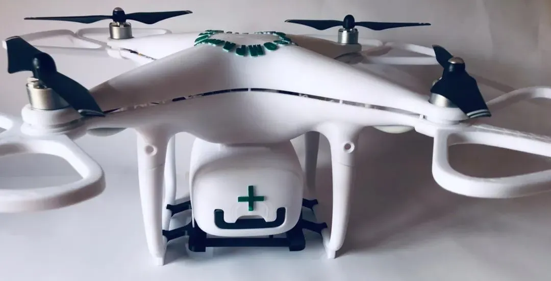
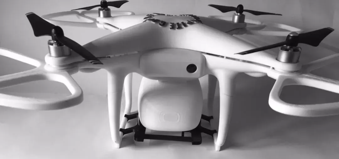
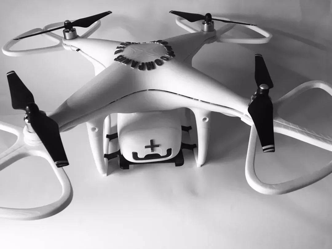
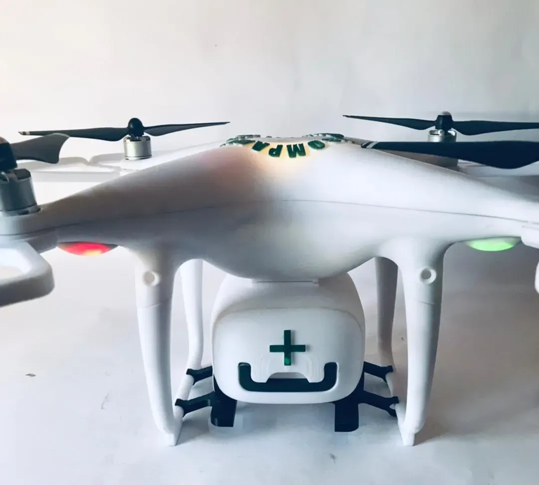

This project is a Phantom-style quadcopter medical delivery drone designed for short-range transport of lightweight medical supplies.
The drone operates using a landing-based delivery approach, where it autonomously travels to a target location, lands, and allows direct access to the payload.
This approach ensures:
- Safe handling of fragile medical supplies
- High delivery accuracy
- Reduced risk to people and property
The system integrates:
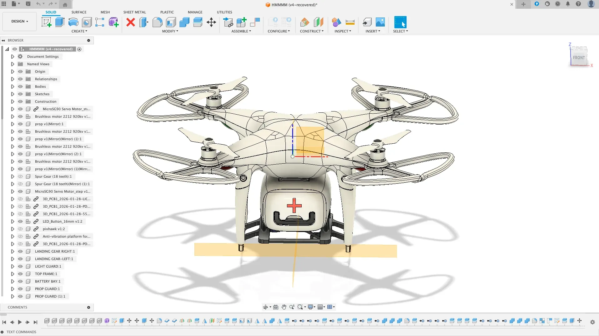
- Custom 3D-designed airframe
- Pixhawk-based flight control
- Custom PCB electronics
- Enclosed medical payload bay
System Architecture
The system is divided into two main subsystems:
1. Flight-Critical System
- Pixhawk 2.4.8 flight controller
- ESCs, motors, GPS, and battery
- Autonomous flight via Mission Planner
2. Payload & Auxiliary System
- Enclosed medical payload bay
- Custom PCB systems (timing, LED control, power distribution)
- Landing-based payload access system
This modular architecture improves:
- Safety
- Reliability
- Ease of troubleshooting
Key Innovations
- Landing-Based Delivery System
- Fully Enclosed Airframe Architecture
- Integrated Medical Payload Bay
- Custom 555 Timer Auxiliary System
- Modular Electronics Architecture
- Custom Power Distribution Design (PCB-based PDB)
Medical Payload Bay Design
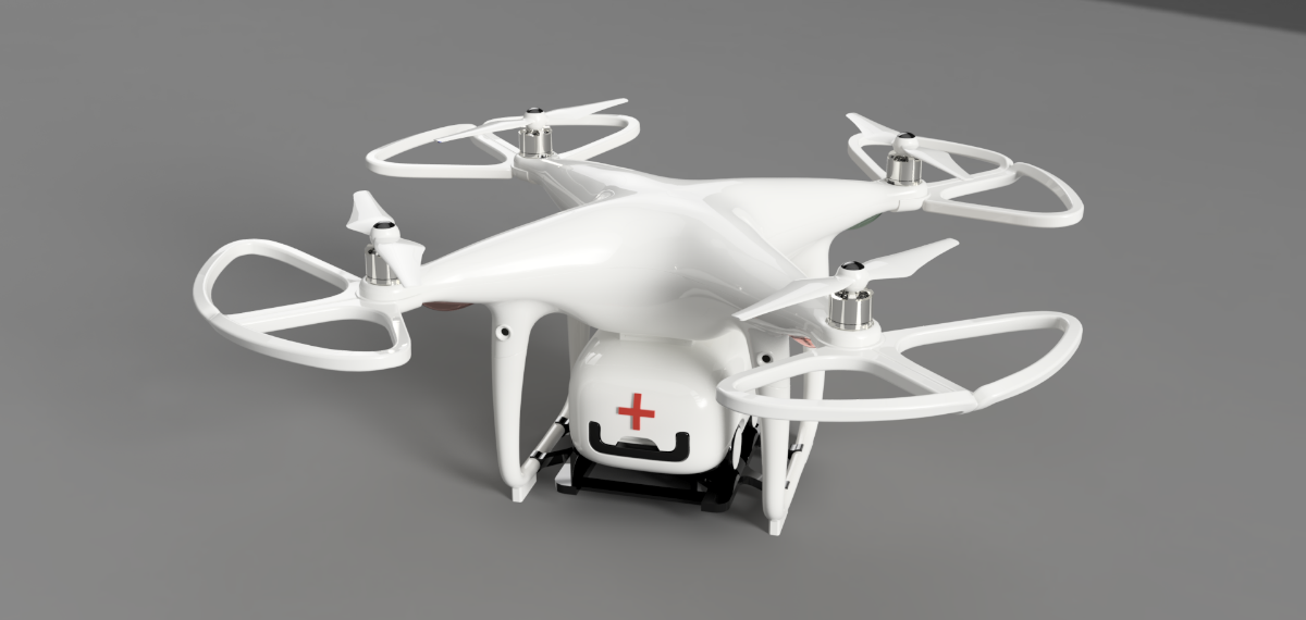
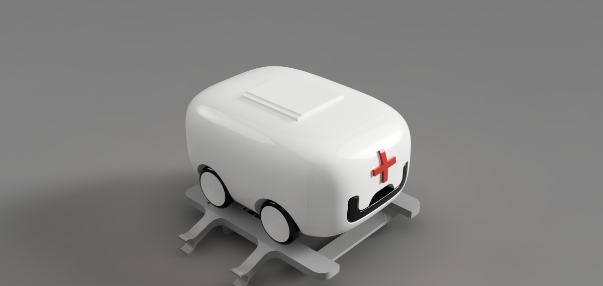
The payload bay is integrated into the drone’s central frame and designed to:
- Protect medical supplies from dust and environmental exposure
- Minimize vibration for sensitive items such as insulin
- Maintain stable flight by aligning with the center of gravity
Unlike aerial drop systems, this design prioritizes controlled ground-level delivery.
Mechanical Design and 3D Printing
All structural components were designed in CAD and optimized for additive manufacturing:
- Frame and arms
- Landing gear
- Payload bay
- Mounting systems
Material Selection:
- ABS (recommended): strong, heat-resistant, impact-tolerant
- PETG: suitable for secondary components
Design features:
- Reinforced stress regions
- Standard fasteners
- 3–3.5 mm wall thickness
Custom Electronics and PCB Design
The project includes three custom PCBs:
1. Dual 555 Timer Control PCB
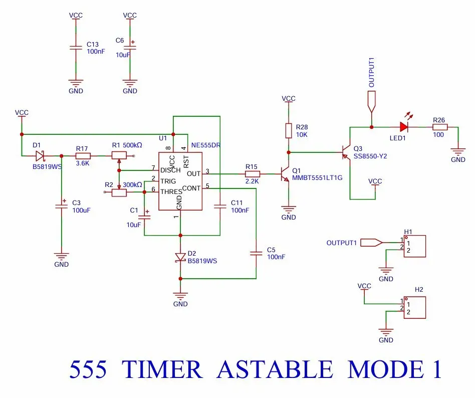
(555 Timer-based LED control circuit with transistor driver stage)
This PCB is built around the 555-timer IC and generates stable timing signals for LED indication and auxiliary control.
The output is amplified using a complementary transistor pair:
- MMBT5551LT1G
- SS8550-Y2
This allows efficient switching of multiple LEDs without overloading the timer IC.
The circuit operates as:
- 555 → signal generator
- NPN → signal amplifier
- PNP → load driver
- LEDs → visual feedback system
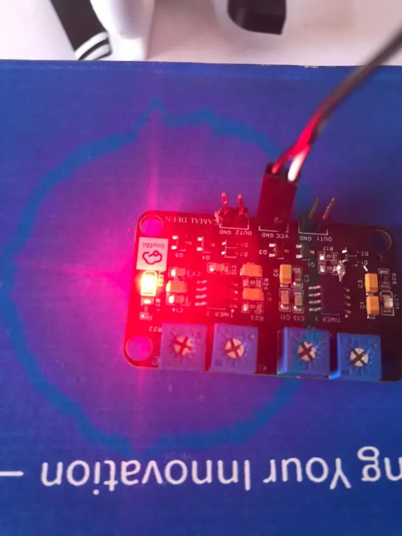
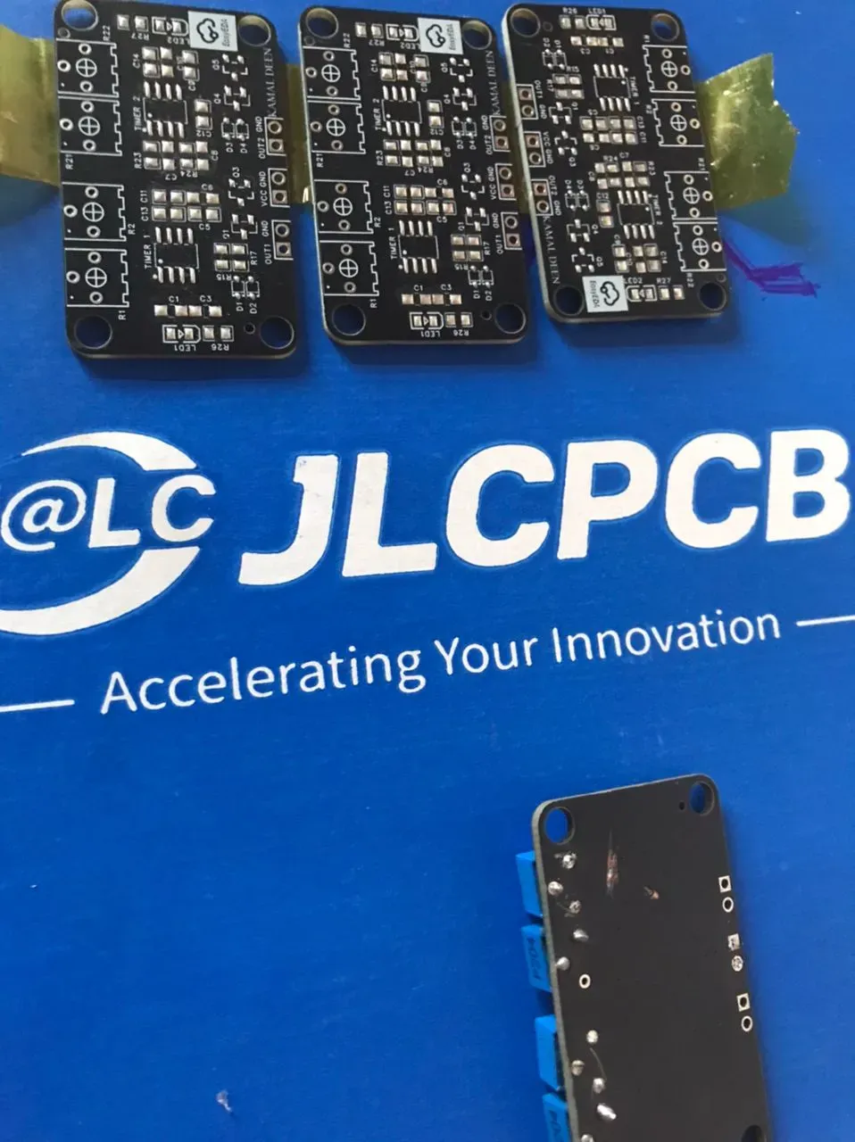
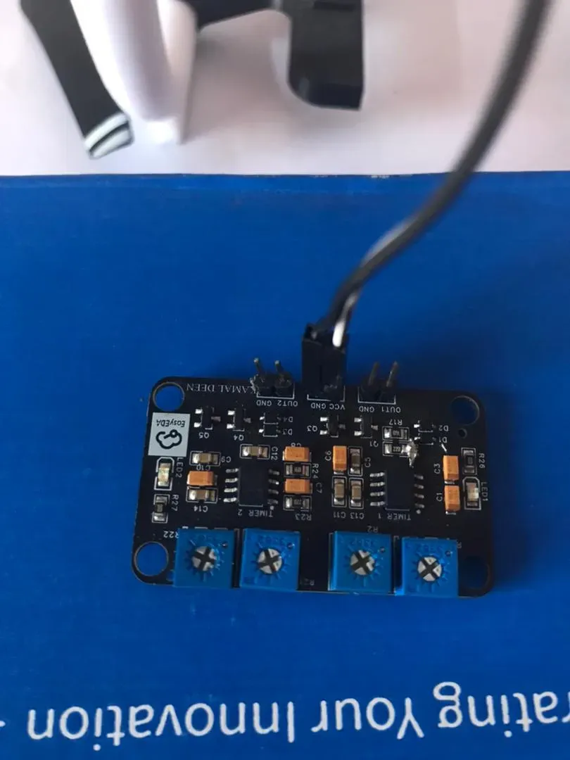
555 Timer ACTUAL PCB SCREENSHOTS
The below screenshots show the 555 timer-based control PCB designed for my Open-source medical delivery drone project (Electronic Wing Project Contest 2026), used for testing timing and signal control in the flight system.
LED Control and Status System (Circuit overview)
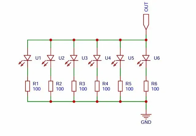
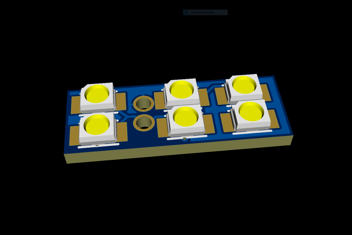
The UAV uses 24 SMD LEDs (6 per arm) arranged across four arms.
Each LED has:
- Its own current-limiting resistor
- Independent protection
- Uniform brightness control
The system uses Vishay 3528 Red + Green LEDs, chosen for high efficiency and low power consumption.
This ensures:
- Equal current distribution
- No thermal imbalance
- Reliable long-term operation
The LED system operates independently from the flight controller for redundancy and reliability.
RENDERED IMAGE OF LED PCB PER DRONE'S ARM
2. Power Distribution Board (Circuit overview)
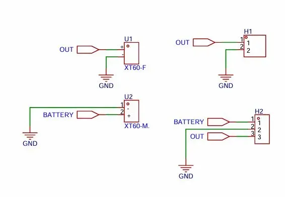
The Power Distribution Board routes power from a 4S LiPo battery to all UAV subsystems using high-current XT connectors.
It supplies power to:
- Pixhawk via dedicated power module
- ESCs for motors
- Auxiliary PCB systems (555 timer board, LEDs)
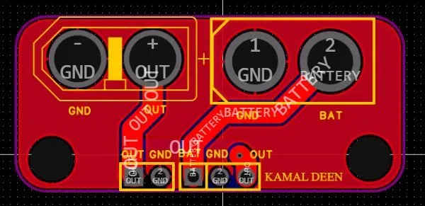
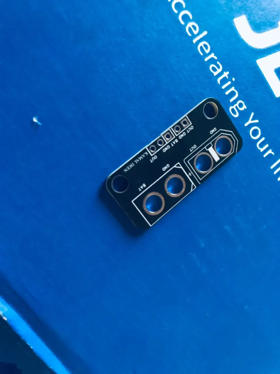
As shown in the PCB screenshots above, this is a passive PCB design, using only copper routing and connectors (no ICs).
Design features:
- Wide copper traces for high current
- Separate routing for power and control systems
- Low resistance and heat generation
This separation reduces electrical noise and improves system stability.
3. LED Control Boards
- 24 LEDs total (6 per arm)
- Current-limited design
- Transistor-driven switching
- Visual system status indication
Commercial Components
- Flight Controller: Pixhawk 2.4.8
- ESCs: 40A BLHeli 32 Bit
- Battery: 4S 3000ma LiPo battery(94mmx34mmx34mm)
- Motors: 2212 920KV(4pieces)
- Motors screws: M3x10(16 pieces or set)
- Frame mounting screws: M2x10(8 pieces or set)
- 9450 Props (2 pieces of Clockwise + 2 pieces of Counterclockwise)
These components ensure reliability and compatibility with open-source ecosystems.
Current Status
- Mechanical design: Completed
- PCB design: Completed
- System integration: Completed
Validation Results
The Open-Source Medical Delivery Drone has successfully completed initial system validation and integration testing.
Key achievements include:
- Successful airframe design, fabrication, and assembly.
- Successful integration of the Pixhawk 2.4.8 flight controller and ArduPilot ecosystem.
- Successful PCB design and fabrication for the 555 Timer Control Board, LED Control Boards, and Power Distribution Board.
- Verification of motor mapping, ESC calibration, and power distribution functionality.
- Successful operation of the LED status indication system.
- Integration and testing of the enclosed medical payload bay.
- Successful flight controller initialization, sensor calibration, and Mission Planner configuration.
- Successful takeoff and stable flight demonstration of the completed drone prototype.
These results confirm the feasibility of the proposed design and demonstrate the successful integration of mechanical, electronic, and flight-control subsystems into a functional medical delivery drone platform.
Impact
This project addresses real healthcare delivery challenges in rural Ghana by:
- Reducing delivery time for medical supplies
- Improving access to essential healthcare resources
- Providing a low-cost, scalable solution
Arming Our Drone
Arming simply means telling the flight controller it is safe to start spinning the motors. In other words, it involves some few steps from ESC calibration (setting up our ESCs) to the point where you command your drone to safely take off with the help of your radio control (transmitter).
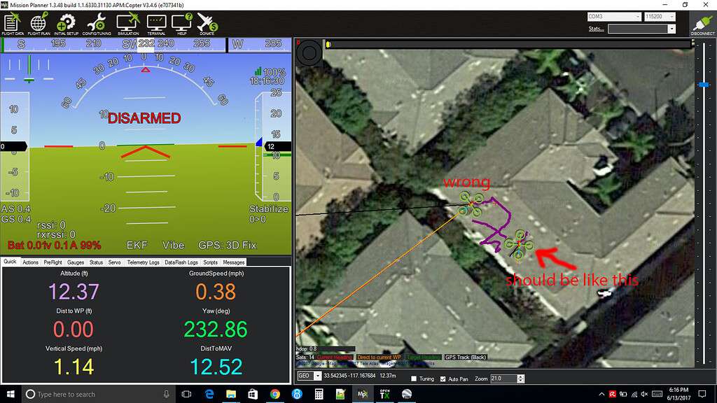
The below screenshot should be how your arming User Interface (UI) be when you connect your Pixhawk 2.4.8 to your host PC.
A bit About Mission Planner (Beginner-Friendly Explanation)
Mission Planner is the official ground control software used for configuring and controlling Pixhawk-based drones. It runs on Windows and acts as the main interface between you and your flight controller.
It is basically the “brain setup tool” for the drone.
What Mission Planner Is Used For
Mission Planner helps you:
1. Configure your Pixhawk 2.4.8
. Load firmware
. Set up radio/receiver
. Calibrate accelerometer, compass, and ESCs
. Configure failsafes (battery, radio loss, GPS loss)
. Assign flight modes (Stabilize, Loiter, AltHold, RTL, Auto, etc.)
2. Plan Autonomous Missions
. Add waypoints on a map
. Set altitude, speed, camera triggers
. Upload mission to Pixhawk
. Run full automatic flights without touching the transmitter
3 Real-Time Flight Monitoring
. View the drone’s position on the map
. Monitor GPS status, battery voltage, RC signal, motor outputs
. See attitude (pitch, roll, yaw), altitude, speed
4 Download Logs & Troubleshoot
. Analyze flight logs
. Check vibration levels
. Detect motor desync, GPS glitches, or battery sag
. Diagnose crashes or performance issues
Why Mission Planner Is Perfect for Beginners
. Simple interface with step-by-step setup wizards
. Clear instructions (big pop-ups tell you what to do next)
. Supports Pixhawk 2.4.8 natively
. Free and constantly updated
. Lots of YouTube tutorials available
Mission Planner is used by:
. Hobby drone builders
. Researchers
FPV tinkerers
. Agriculture drones
. Mapping/surveying drones
. VTOL and hybrid builds
. Military-style autonomous projects
What You Need Before Using Mission Planner
1.Pixhawk 2.4.8 connected via USB
2.Micro USB cable
3.Optional: Telemetry radio (for wireless connection)
Mission Planner automatically detects COM port and board type.
Download Link
Official Download (Latest Version):
🔗 https://firmware.ardupilot.org/Tools/MissionPlanner/
(This is the safest, official ArduPilot hosting server.)
Full Beginner Setup Guide — From ESC Calibration to First Flight
This guide walks a total beginner through the entire startup process of your Pixhawk-based Open-Source Medical Delivery Drone.
1. ESC Calibration (Using Pixhawk)
Before the drone can fly, the ESCs must know the throttle range. This ensures all motors start at the same time and respond evenly.
STEP A — Safety First
. Remove all propellers
. Keep the battery disconnected
STEP B — Connect to Mission Planner
. Plug Pixhawk into your laptop via USB
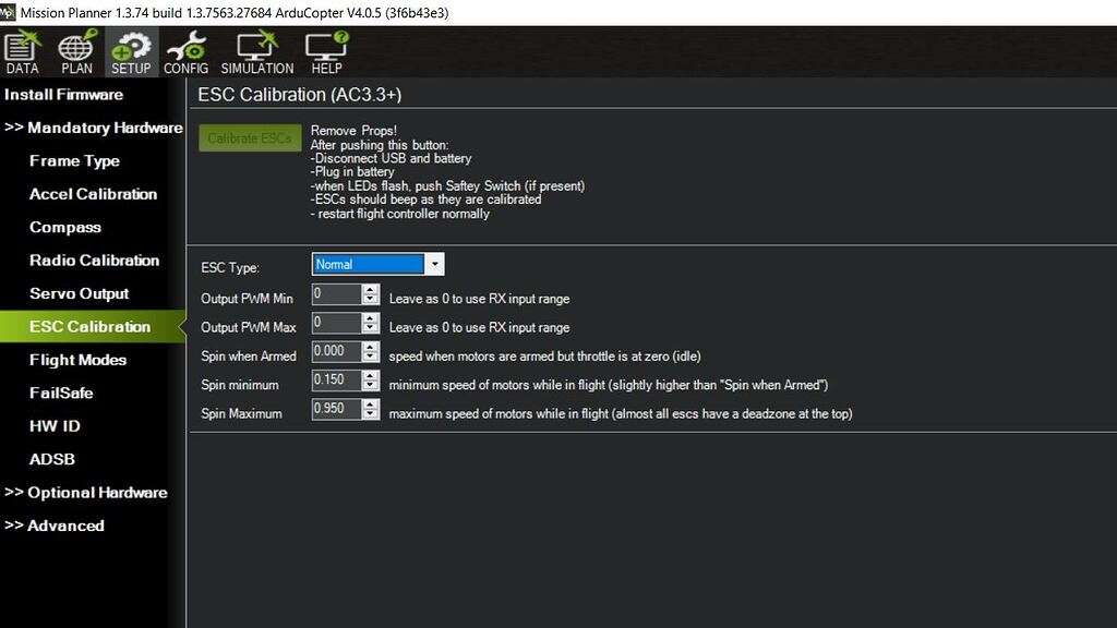
. Open Mission Planner → Mandatory Hardware → ESC Calibration
STEP C — Begin Calibration
. Check the box “Calibrate ESCs”
. Disconnect USB
. Now plug in the battery
. Pixhawk will send full throttle → ESC beeps
. Then it sends minimum throttle → ESC confirms
STEP D — Complete
. Unplug battery
. Reconnect to Mission Planner
. ESCs are now synced.
This guarantees smooth motor startup, especially with OneShot-compatible ESCs.
2. Motor Direction Check
STEP A — Use Mission Planner → Motor Test
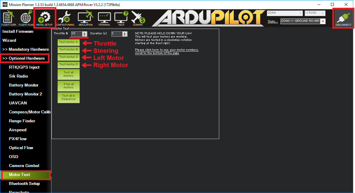
This spins each motor one at a time.
STEP B — Confirm Direction
Standard X-quad orientation:
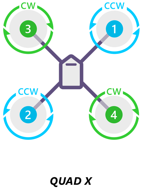
Motor 1: Front Right → Clockwise
Motor 2: Back Right → Counter-clockwise
Motor 3: Back Left → Clockwise
Motor 4: Front Left → Counter-clockwise
STEP C — Fix Any Wrong Motor Direction
Note: Just swap any two wires on that motor’s ESC output.
3. Flight Controller Sensor Calibration
Mandatory calibrations for beginners:
1.Accelerometer Calibration
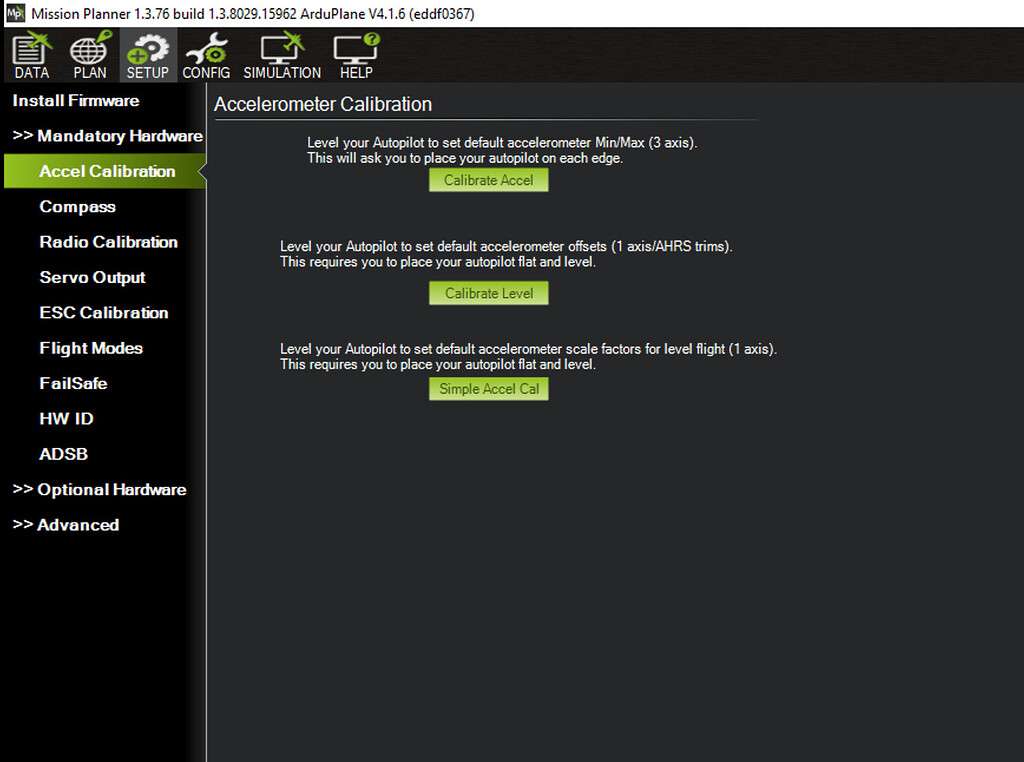
. Keep the drone level and follow all orientation steps.
2.Compass Calibration
Mandatory Hardware --- Accel Calibration --- as shown above
. Rotate drone in all directions until the progress bar completes.
3.Radio Calibration
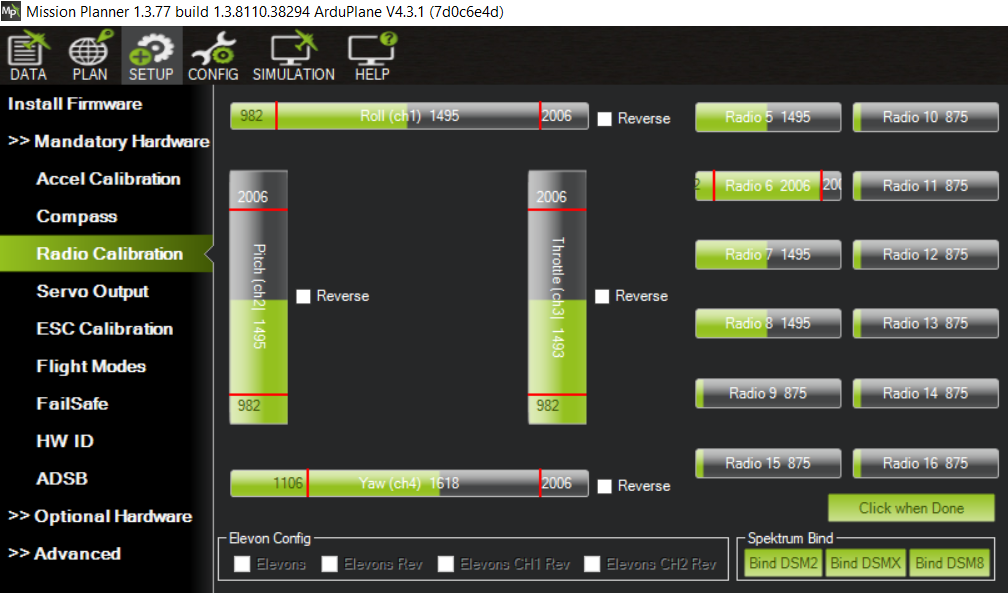
. Move sticks to maximum in every direction → Save
4.GPS Fix
. Wait for 6–8 satellites minimum
. LED becomes steady green or blue (depending on firmware)
Note: Without these, Pixhawk will refuse to arm, which protects beginners.
4. Installing Transmitter & Receiver
Recommended Beginner Radios
. Radiomaster TX12 / TX16 with ExpressLRS receiver
. FrSky Taranis QX7 with SBUS receiver
Budget option: FlySky i6X with PPM receiver
Receiver → Pixhawk Wiring
. SBUS → RC IN (preferred)
. PPM → RC IN (also works)
. ELRS → UART → set to CRSF serial in Mission Planner
After wiring:
Go to Radio Calibration → move all sticks → confirm channels move correctly.
5 Power System Setup
Your PDB connections include:
. XT90 → Main battery input
. XT60 → 4-in-1 ESC power
. Pixhawk 2.4.8 power module connector
. 16 mm LED button for lighting or manual input
Verify voltages using a multimeter:
. PDB → Pixhawk 5V regulator output = 4.9–5.3V
. ESC VBAT = 10–22V depending on battery
6. Arming the Drone
Pixhawk requires checks before motors spin.
Method 1 — RC Transmitter
. Throttle down
. Throttle down + Yaw right (hold 2 seconds)
Note: Motors beep → Drone is armed.
Method 2 — Mission Planner
. Go to Actions tab
. Click ARM
. Motors twitch → Armed
Disarm
Throttle down + yaw left (or press “Disarm” in Mission Planner)
7. Pre-Flight Checklist (Very Beginner Friendly)
. Propellers installed in correct direction
. Battery secured with straps
. GPS has 8+ satellites
. RC transmitter ON
. Flight mode set to:
Stabilize → AltHold → Loiter
. Antenna mounted properly
. No wires touching propellers
. Landing area clear
. Weather calm (no wind for beginners)
8. First Takeoff (Beginner Mode)
STEP A — Set to AltHold or Loiter
These modes self-level and hold altitude.
STEP B — Slowly increase throttle
Drone should:
. Lift evenly
. Hover with no drift
. Respond smoothly to stick input
STEP C — Small hover test
Just hold your Phantom drone 1 meter above ground for 10–20 seconds.
9. In-Flight Tips for Beginners
. Tiny stick movements only
. Stay in Loiter if you’re nervous
. Never fly behind yourself — keep the drone facing forward
. Land as soon as battery hits 30%
. Never push maximum throttle indoors or without GPS
10. Safe Landing
. Enter Loiter
. Reduce throttle slowly
. Touch down gently
. Disarm
. Disconnect battery
Note: Always remove battery before handling the drone.
GPS Selections
Recommended GPS Module for our Pixhawk 2.4.8
A popular, reliable choice is u‑blox NEO‑M10N GPS module (or its newer variant with integrated compass/antenna).
Why NEO-M10N (or similar) is a strong fit
. It supports multiple GNSS constellations — GPS, GLONASS, BeiDou, etc. — which improves satellite lock speed and reliability even in difficult environments.
. Comes with built-in compass / magnetometer + ceramic patch antenna — important for heading/orientation data and for autopilot functions.
. Compact and lightweight — convenient for UAV and drone use where space and weight matter. Flying Tech+1
. Compatible out-of-the-box with Pixhawk via standard GPS port / connector.
Because of those strengths, the NEO-M10N (or newer variants like NEO-M9N) is widely accepted as a “go-to” GPS for Pixhawk-based drones, whether for hobby builds or more serious UAVs.
Mounting GPS Inside a Phantom-Style Frame — What to Know, What to Avoid
Mounting internally (i.e. inside the drone body/shell rather than on a mast) can work, but it comes with trade-offs. Here’s how to do it — if we must — and what to watch out for.
What you should do if mounting internally
. Choose a non-metallic / non-conductive and non-magnetic mounting area (e.g. plastic or fiberglass plate, away from carbon-fiber if possible)
. Keep some minimum clearance — try to place the GPS module under a thin shell or cover, not buried under thick metal or dense carbon/metal + battery shielding
. Orient the GPS so its “arrow/heading mark” points to the front of the drone (to align compass heading with drone’s nose/front) — orientation matters for accurate compass/GPS data.
. If possible, use a vibration-isolation or soft pad under GPS module — this helps reduce noise from motors/prop vibrations that can affect GPS reception.
. Route the GPS cable carefully, avoiding heavy current-carrying wires (battery leads, ESC power wires, etc.) — these can create electromagnetic interference and degrade GPS/compass performance.
What you risk if you mount internally
. Reduced satellite visibility — metal, carbon fiber, battery pack, or other obstructions can block GPS signal. Some in the drone community say mounting GPS under frame or battery often leads to poor reception or no lock. (One user comment: “you will never get a gps lock through carbon fibre + battery”.).
. Compass interference / magnetic distortion — carbon fiber frames, motors, ESCs, batteries, and wiring can disturb the compass’s magnetic sensor, leading to heading errors or unreliable navigation. Many flight-controller guides advise mounting compass/GPS “as far away from motor/ESC/power wiring as possible.”
. Less reliable GPS fix — because of the weaker antenna reception, satellites may fail to lock, or signal may fluctuate, which can break autonomous modes or failsafes.
My Recommendation (Given Your Design)
Because i want the project to be “easy-to-build / replicable for beginners,
. Keep GPS away from the battery cables, ESCs and mount it on a non-metallic structure or on a small mast inside the frame.
This ensures at least good satellite reception and compass reliability, which makes setup less error prone. However, the GPS must be mounted externally.
In short — internal mounting can be done, but external must remain far safer and more reliable, especially for first builds.
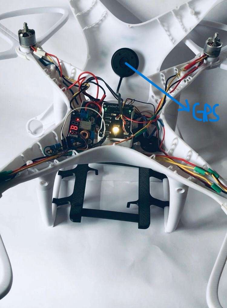
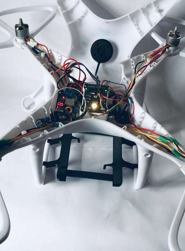
The above image shows how i mounted the GPS internally in the top frame.
Challenges Encountered
During development, the project faced several challenges including the lack of access to a personal 3D printer, multiple airframe design iterations, PCB fabrication delays, flight controller integration, and system testing. These challenges were overcome through repeated prototyping, extensive CAD redesign, and careful system validation.
Alignment with Electronic Wing Project Contest 2026
This project demonstrates:
- Open-source hardware design
- Practical engineering implementation
- Real-world humanitarian application
All design files, schematics, and documentation will be openly shared to support learning and replication.
Project Development Cost Breakdown
The total development cost of this Open-Source Medical Delivery Drone was approximately USD $945, funded primarily through personal investment.
| Item | Estimated Cost (USD) |
|---|---|
| Custom 3D Printed Airframe Components | $600 |
| Pixhawk 2.4.8 Flight Controller Kit (including GPS and accessories) | $80 |
| Brushless Motors (4x) | $50 |
| Electronic Speed Controllers (ESCs) | $25 |
| Propellers (4x) | $10 |
| Battery & Power Components | $20 |
| Radio Receiver & Communication Hardware | $70 |
| Wiring, Connectors & Assembly Materials (3528 LEDs,100-ohm resistors) | $20 |
| 555 Timer PCBA (Printed Circuit Board Assembly) and LEDs PCBs Fabrication | $70 |
| Total Estimated Cost | $945 |
A significant portion of the project budget was dedicated to manufacturing the custom-designed airframe. Since I did not own a personal 3D printer during development, approximately $600 was invested in professional 3D printing services to fabricate the drone structure and support multiple design iterations. The remaining budget covered flight electronics, propulsion components, power systems, communication hardware, and assembly materials.
This project demonstrates how open-source technologies, engineering persistence, and personal investment can be combined to create a functional medical delivery drone prototype capable of supporting future humanitarian and healthcare logistics applications.
Design Demonstrations
The following videos demonstrate how i designed the frame in Autodesk Fusion 360
System Validation (Video Demonstrations)
The following videos show initial system validation, including internal electronics, custom PCB operation, power distribution, and flight controller initialization and final takeoff:
Final Takeoff Video Demo
System Integration Overview
Complete custom drone design developed in Fusion 360, featuring full structural and electronic integration. The system includes an enclosed airframe, Pixhawk flight controller, ESC, power distribution, and optimized wiring layout. All motors are correctly mapped and synchronized, while LED indicators and system tests confirm stable power delivery and functionality.
The following images document the transition from CAD design and electronic schematics to real-world hardware implementation, highlighting system integration, layout optimization, and full system assembly of the UAV.