
CHAKRA - Smart E-Wheelchair with Dual Control and Integrated Pressure Monitoring System for Differently-abled Individuals
CHAKRA is a Smart E-Wheelchair designed to enhance mobility, independence, and safety for differently-abled individuals. The system combines dual-control operation using voice commands and joystick control, obstacle detection using ultrasonic sensors, and an integrated pressure monitoring system using FSR sensors.
Unlike conventional wheelchairs that focus only on mobility, CHAKRA continuously monitors user posture and pressure distribution to help reduce the risk of pressure ulcers caused by prolonged sitting. The project was developed as a low-cost retrofit solution that can transform an existing manual wheelchair into a smart assistive mobility platform.
What Makes CHAKRA Different ?
Most smart wheelchair projects focus primarily on navigation and movement. CHAKRA goes beyond mobility by integrating preventive healthcare monitoring into the wheelchair itself.
Key differentiators include:
• Dual-control operation using both voice commands and joystick control.
• Real-time pressure monitoring using six FSR-406 sensors embedded within the seat cushion.
• Posture detection and alert system to encourage healthy seating behavior.
• Obstacle detection for safer navigation.
• Low-cost retrofit approach that upgrades an existing wheelchair instead of requiring a completely new smart wheelchair.
This combination makes CHAKRA both practical and affordable for everyday use.
Why It Matters ?
According to the World Health Organization (WHO), approximately 65 million people worldwide require wheelchairs, yet only 5-15% have access to them. In addition, pressure ulcers affect nearly 54% of wheelchair users, making them one of the most common long-term health complications.
Many users depend on wheelchairs for several hours each day, increasing the risk of prolonged pressure concentration and poor posture. CHAKRA addresses these challenges by combining mobility assistance and health monitoring within a single platform, helping users move safely while also promoting better seating habits.
The Big Picture
CHAKRA was developed through multiple stages, beginning with a small-scale mobility prototype, followed by a voice and joystick control prototype, and finally a fully integrated Smart E-Wheelchair with dual-control operation, obstacle detection, and pressure monitoring. The following sections document the complete development journey from concept to final implementation.
Step 1: Initial Prototype Development
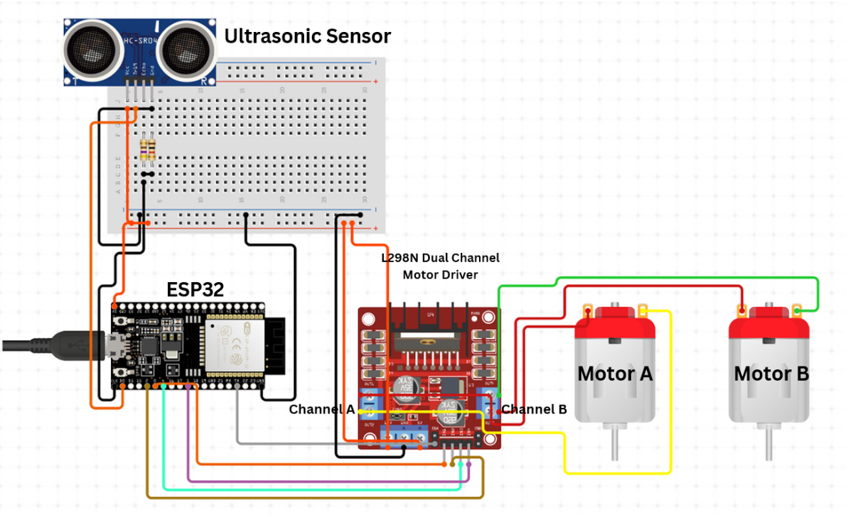
The project began with a small-scale wheelchair prototype designed to replicate the movement logic of the final E-wheelchair. The prototype used an ESP32, L298N motor driver, two DC motors, and ultrasonic sensors for obstacle detection. Control was provided through the Arduino Bluetooth Controller mobile app using both joystick-style directional buttons and voice commands. This phase was used to validate forward, backward, left, right, and stop movements, test obstacle detection performance, and refine the control logic before implementing the full-scale wheelchair system.
Step 1 – System Planning
The initial wheelchair-like prototype was designed to validate movement control and obstacle detection before developing the full-scale system.
Step 2 – Schematic Design
A circuit was developed using ESP32, L298N motor driver, two DC motors, and HC-SR04 ultrasonic sensors for navigation and obstacle detection.
Step 3 – Arduino IDE Setup
The ESP32 board package and required libraries were installed in Arduino IDE. Control logic for movement and obstacle detection was developed and tested.
- Install the BluetoothSerial library by selecting Sketch -> Include Library -> Manage Libraries in the Arduino IDE
Add these URLs by selecting File -> Preferences -> Additional Boards Manager URLs
https://dl.espressif.com/dl/package_esp32_index.json, https://raw.githubusercontent.com/espressif/arduino-esp32/package_esp32_index.json
Step 4 – Programming and Testing
The prototype was programmed to perform forward, backward, left, right, and stop movements. Ultrasonic sensors were tested at different distances to verify obstacle detection functionality.
- Copy this code in Arduino IDE , compile and upload.
#include <BluetoothSerial.h>
BluetoothSerial SerialBT;

// Motor Pins
#define ENA 5
#define IN1 18
#define IN2 19
#define ENB 21
#define IN3 22
#define IN4 23

// Ultrasonic Sensor Pins
#define TRIG_PIN 25
#define ECHO_PIN 26

int speedValue = 1023; // PWM speed

void setup() {
  Serial.begin(115200);

  pinMode(ENA, OUTPUT);
  pinMode(IN1, OUTPUT);
  pinMode(IN2, OUTPUT);
  pinMode(ENB, OUTPUT);
  pinMode(IN3, OUTPUT);
  pinMode(IN4, OUTPUT);

  pinMode(TRIG_PIN, OUTPUT);
  pinMode(ECHO_PIN, INPUT);

  stopMotors();

  SerialBT.begin("ESP32_Wheelchair");
  Serial.println("Bluetooth started. Pair and send commands.");
}

void loop() {
  if (SerialBT.available()) {
    String cmd = SerialBT.readStringUntil('\n');
    cmd.trim();
    cmd.toLowerCase();

    Serial.println("Command received: " + cmd);

    if (cmd == "fs" || cmd == "forward") {
      moveForward();
    }
    else if (cmd == "bs" || cmd == "backward") {
      moveBackward();
    }
    else if (cmd == "ls" || cmd == "left") {
      moveLeft();
    }
    else if (cmd == "rs" || cmd == "right") {
      moveRight();
    }
    else if (cmd == "s" || cmd == "x" || cmd == "stop") {
      stopMotors();
    }
    else {
      Serial.println("Unknown command");
      stopMotors();
    }
  }

  // If moving forward, continuously check distance
  if (isMovingForward()) {
    long distance = readUltrasonicDistance();
    Serial.println("Distance: " + String(distance) + " cm");

    if (distance > 0 && distance < 15) {
      Serial.println("Obstacle detected! Stopping motors.");
      stopMotors();
    }
  }
}

// Function to read distance from ultrasonic sensor
long readUltrasonicDistance() {
  digitalWrite(TRIG_PIN, LOW);
  delayMicroseconds(2);

  digitalWrite(TRIG_PIN, HIGH);
  delayMicroseconds(10);
  digitalWrite(TRIG_PIN, LOW);

  long duration = pulseIn(ECHO_PIN, HIGH, 30000); // Timeout at 30 ms
  if (duration == 0) return -1; // No reading

  long distance = duration * 0.034 / 2;
  return distance;
}

// Check if currently moving forward
bool isMovingForward() {
  return digitalRead(IN2) == HIGH && digitalRead(IN3) == HIGH;
}
void moveForward() {
  digitalWrite(IN1, LOW);
  digitalWrite(IN2, HIGH);
  digitalWrite(IN3, HIGH);
  digitalWrite(IN4, LOW);
  analogWrite(ENA, speedValue);
  analogWrite(ENB, speedValue);
  Serial.println("Moving Forward");
}
void moveBackward() {
  digitalWrite(IN1, HIGH);
  digitalWrite(IN2, LOW);
  digitalWrite(IN3, LOW);
  digitalWrite(IN4, HIGH);
  analogWrite(ENA, speedValue);
  analogWrite(ENB, speedValue);
  Serial.println("Moving Backward");
}
void moveLeft() {
  digitalWrite(IN1, HIGH);
  digitalWrite(IN2, LOW);
  digitalWrite(IN3, HIGH);
  digitalWrite(IN4, LOW);
  analogWrite(ENA, speedValue);
  analogWrite(ENB, speedValue);
  Serial.println("Turning Left");
}
void moveRight() {
  digitalWrite(IN1, LOW);
  digitalWrite(IN2, HIGH);
  digitalWrite(IN3, LOW);
  digitalWrite(IN4, HIGH);
  analogWrite(ENA, speedValue);
  analogWrite(ENB, speedValue);
  Serial.println("Turning Right");
}
void stopMotors() {
  digitalWrite(IN1, LOW);
  digitalWrite(IN2, LOW);
  digitalWrite(IN3, LOW);
  digitalWrite(IN4, LOW);
  analogWrite(ENA, 0);
  analogWrite(ENB, 0);
  Serial.println("Motors Stopped");
}
Step 5 – Hardware Prototype Assembly
The hardware prototype was assembled using ESP32, L298N motor driver, two DC motors, wheels, battery pack, and ultrasonic sensors. The Arduino Bluetooth Controller mobile app was used to test directional control and voice-command-based movement.
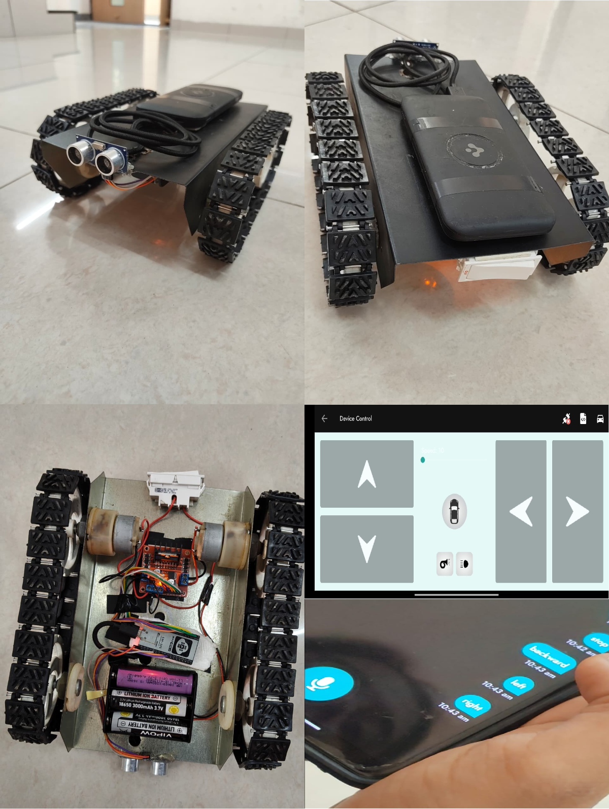
Step 6 – Validation
The prototype successfully validated navigation control, obstacle detection, and movement logic, forming the foundation for the next development stage.
Step 2: Voice and Joystick Control Prototype
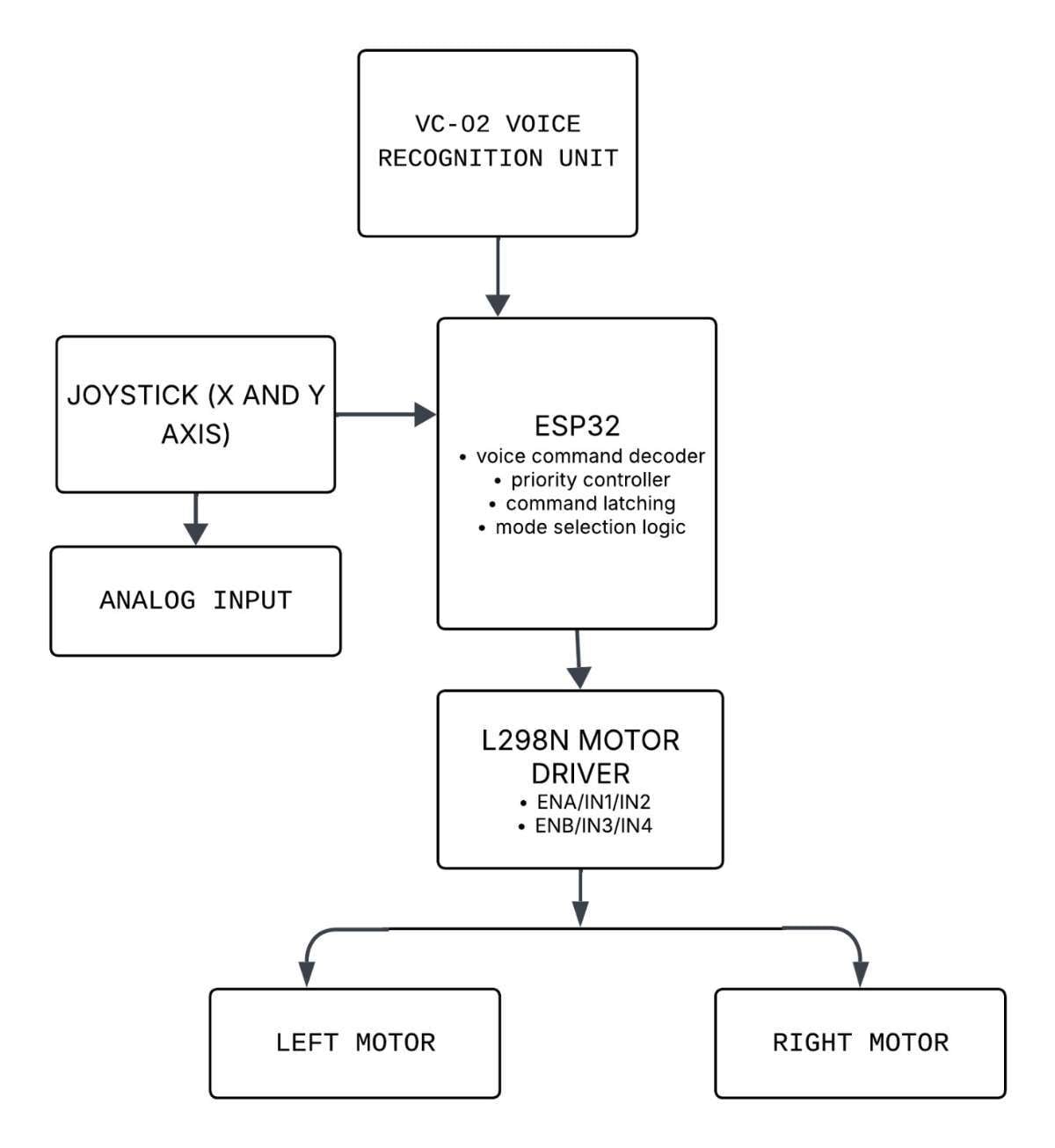
The second prototype focused on implementing a dual-control system using a VC-02 Voice Recognition Module and a 2-axis joystick module. The objective was to enable both hands-free and manual wheelchair control, while validating command recognition, directional movement, and overall system responsiveness before integration into the final Smart E-Wheelchair.
Step 1 – Component Selection
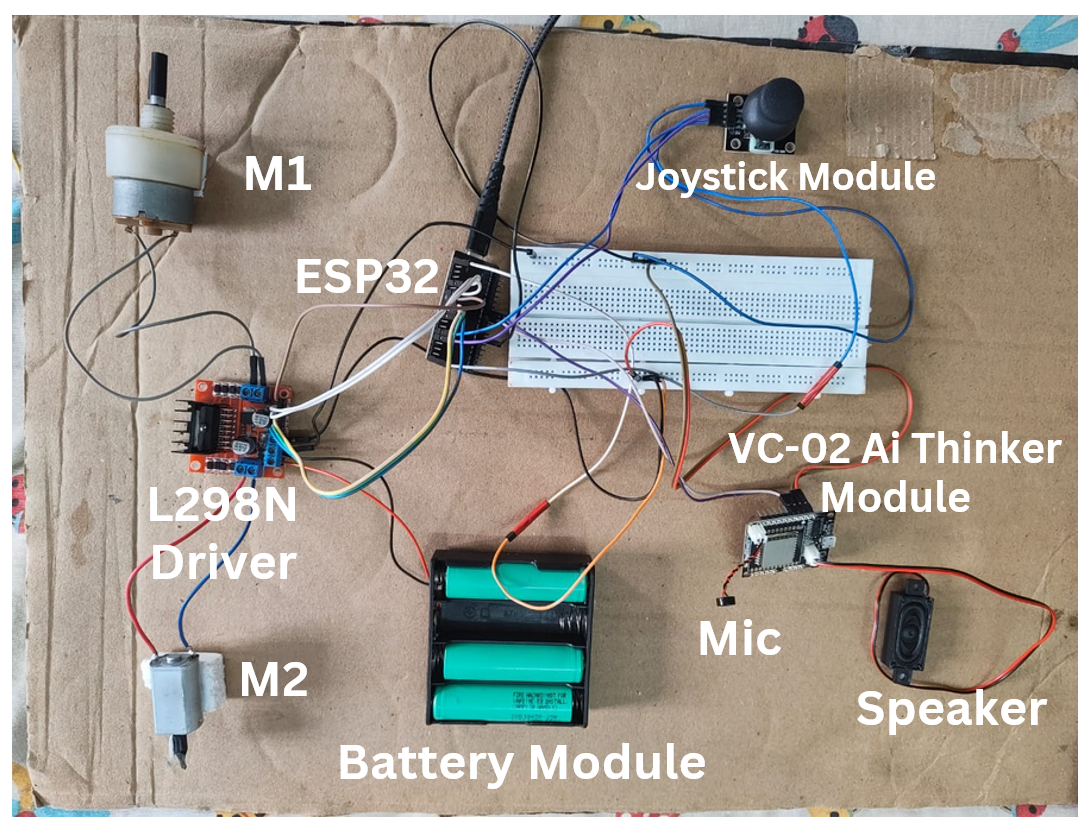
The prototype was developed using an ESP32, VC-02 Ai Thinker Voice Recognition Module, Dual-Axis Joystick Module, L298N Motor Driver, two DC motors, microphone, speaker, and battery pack.
Step 2 – Circuit Integration
The joystick and VC-02 voice module were interfaced with the ESP32. The L298N motor driver was used to control the two DC motors based on user inputs.
Block Diagram:
Step 3 – Arduino IDE Programming
Control logic was developed to process both joystick movements and offline voice commands. The VC-02 module was trained with basic commands such as Forward, Backward, Left, Right, and Stop.
/* =========================================
   VOICE + JOYSTICK CONTROLLED SYSTEM
   ESP32 + VC-02 + L298N
   ========================================= */

// ---------- L298N ----------
#define ENA 25
#define IN1 26
#define IN2 27
#define ENB 14
#define IN3 12
#define IN4 13

// ---------- JOYSTICK ----------
#define JOY_X 34
#define JOY_Y 35

// ---------- VC-02 ----------
#define VC_RX 16
#define VC_TX 17

// ---------- PWM ----------
#define PWM_FREQ 20000
#define PWM_RES  8
#define SPEED_FWD 180
#define SPEED_TURN 130

// ---------- VC-02 COMMANDS ----------
#define CMD_FORWARD  0xA190
#define CMD_BACKWARD 0xA191
#define CMD_RIGHT    0xA192
#define CMD_LEFT     0xA193
#define CMD_STOP     0xA194

// ---------- JOYSTICK ----------
#define JOY_CENTER_MIN 1700
#define JOY_CENTER_MAX 2300
#define JOY_MIN 1000
#define JOY_MAX 3000

// ---------- CONTROL MODE ----------
enum ControlMode { MODE_VOICE, MODE_JOYSTICK };
ControlMode mode = MODE_JOYSTICK;

uint16_t lastCommand = CMD_STOP;

// =========================================

void setup() {
  Serial.begin(115200);
  Serial2.begin(9600, SERIAL_8N1, VC_RX, VC_TX);

  pinMode(IN1, OUTPUT);
  pinMode(IN2, OUTPUT);
  pinMode(IN3, OUTPUT);
  pinMode(IN4, OUTPUT);

  ledcAttach(ENA, PWM_FREQ, PWM_RES);
  ledcAttach(ENB, PWM_FREQ, PWM_RES);

  stopMotors();
  Serial.println("System Ready");
}

// =========================================

void loop() {

  // -------- VOICE INPUT ----------
  if (Serial2.available() >= 2) {
    uint16_t cmd = (Serial2.read() << 8) | Serial2.read();

    // Ignore duplicate packets
    if (cmd != lastCommand) {
      lastCommand = cmd;

      Serial.print("Voice CMD: 0x");
      Serial.println(cmd, HEX);

      if (cmd == CMD_STOP) {
        stopMotors();
        mode = MODE_JOYSTICK;   // joystick enabled
      } else {
        mode = MODE_VOICE;      // voice takes control
      }
    }
  }

  // -------- EXECUTION ----------
  if (mode == MODE_VOICE) {
    switch (lastCommand) {
      case CMD_FORWARD:  forward();  break;
      case CMD_BACKWARD: backward(); break;
      case CMD_LEFT:     left();     break;
      case CMD_RIGHT:    right();    break;
    }
  }
  else { // MODE_JOYSTICK
    joystickControl();
  }
}

// =========================================
// JOYSTICK CONTROL
// =========================================
void joystickControl() {
  int x = analogRead(JOY_X);
  int y = analogRead(JOY_Y);

  // DEAD ZONE
  if (x > JOY_CENTER_MIN && x < JOY_CENTER_MAX &&
      y > JOY_CENTER_MIN && y < JOY_CENTER_MAX) {
    stopMotors();
    return;
  }

  if (y > JOY_MAX)        forward();
  else if (y < JOY_MIN)   backward();
  else if (x > JOY_MAX)   right();
  else if (x < JOY_MIN)   left();
}

// =========================================
// MOTOR FUNCTIONS
// =========================================
void forward() {
  digitalWrite(IN1, HIGH);
  digitalWrite(IN2, LOW);
  digitalWrite(IN3, HIGH);
  digitalWrite(IN4, LOW);
  ledcWrite(ENA, SPEED_FWD);
  ledcWrite(ENB, SPEED_FWD);
}

void backward() {
  digitalWrite(IN1, LOW);
  digitalWrite(IN2, HIGH);
  digitalWrite(IN3, LOW);
  digitalWrite(IN4, HIGH);
  ledcWrite(ENA, SPEED_FWD);
  ledcWrite(ENB, SPEED_FWD);
}

void right() {
  digitalWrite(IN1, LOW);
  digitalWrite(IN2, HIGH);
  digitalWrite(IN3, HIGH);
  digitalWrite(IN4, LOW);
  ledcWrite(ENA, SPEED_TURN);
  ledcWrite(ENB, SPEED_FWD);
}

void left() {
  digitalWrite(IN1, HIGH);
  digitalWrite(IN2, LOW);
  digitalWrite(IN3, LOW);
  digitalWrite(IN4, HIGH);
  ledcWrite(ENA, SPEED_FWD);
  ledcWrite(ENB, SPEED_TURN);
}

void stopMotors() {
  digitalWrite(IN1, LOW);
  digitalWrite(IN2, LOW);
  digitalWrite(IN3, LOW);
  digitalWrite(IN4, LOW);
  ledcWrite(ENA, 0);
  ledcWrite(ENB, 0);
}
Step 4 – Hardware Assembly
All components were assembled on a prototype board and tested with the motor driver, motors, microphone, speaker, and battery module.
Step 5 – Testing and Validation
The prototype successfully achieved dual-control operation using both joystick and voice commands. This phase validated the control system before integration into the final wheelchair platform.
Step 3: Final Smart E-Wheelchair Development
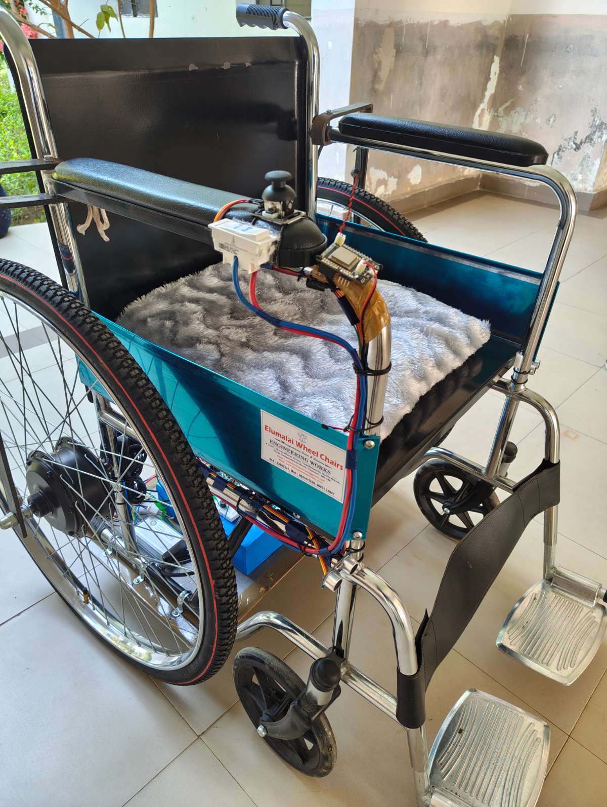
After successfully validating the previous prototypes, the final phase focused on converting a conventional manual wheelchair into a fully functional Smart E-Wheelchair. This stage involved integrating dual-control operation, BLDC hub motor drive, obstacle detection, and pressure monitoring into a single platform, resulting in an affordable assistive mobility solution that enhances both user independence and safety.
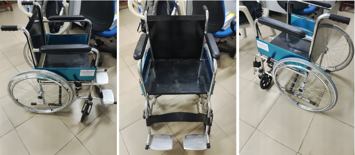
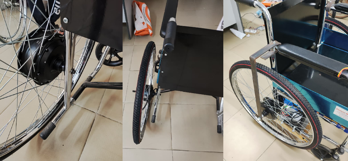
Step 1 – Wheelchair Selection and Mechanical Modifications
A standard manual wheelchair was selected as the base platform.
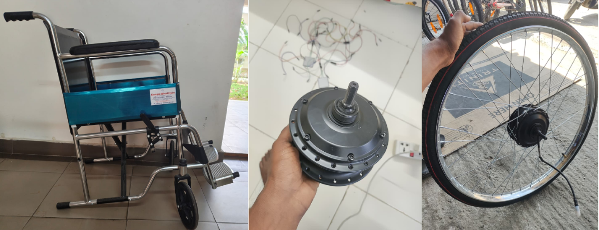
The original rear wheels were not suitable for hub motor integration because they contained only 28 spokes. Therefore, new 40-spoke 26x1 1/2'' bicycle wheels were assembled and integrated with 24V, 350W BLDC hub motors having 40 spoke mounting holes to ensure proper wheel strength, balance, and load handling.
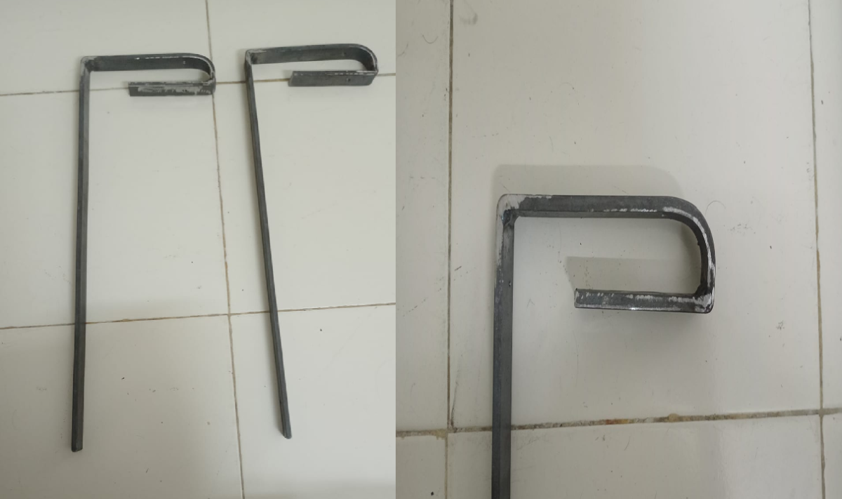
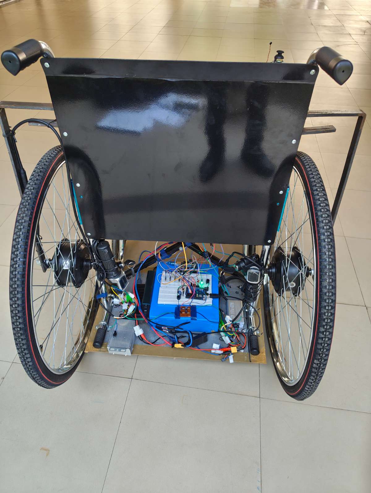
Step 2 – Fabrication of Motor Mounting and Support Structure
Custom metal side-frame brackets were fabricated and installed on both sides of the wheelchair to securely support the BLDC hub motors.
A rigid support platform was also fabricated using metal rods and sheet metal to hold the battery pack, motor controllers, and electronic modules. The structure was mounted beneath the wheelchair using clamp screws to provide stability and proper weight distribution.
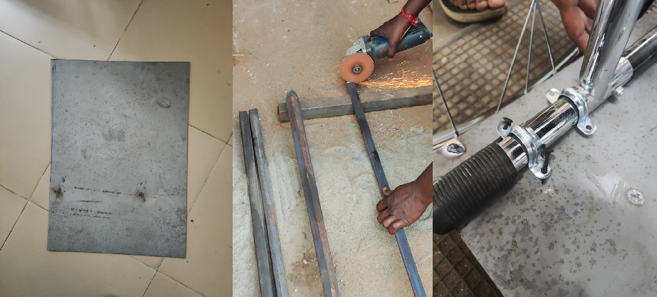
Hub motors were fixed on both sides of the wheelchair with supporting metal frames tightened with fasteners.
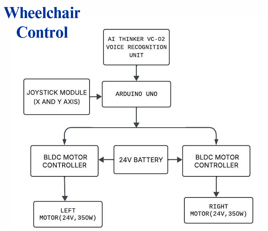
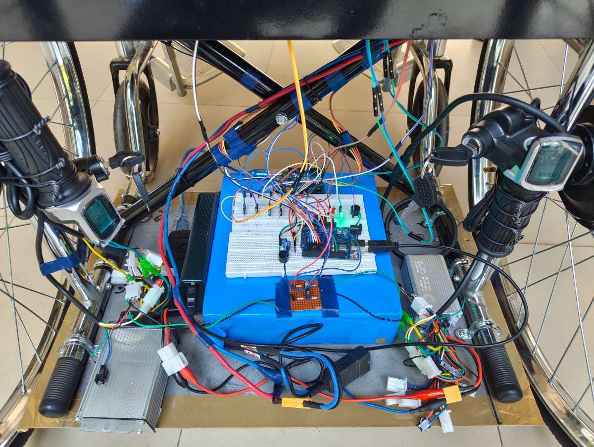
Step 3 – Wheelchair Control System
The wheelchair control system was developed using:
- Arduino UNO
- VC-02 Ai Thinker Voice Recognition Module
- Dual-Axis Joystick Module
- Two 24V 350W BLDC Hub Motors
- Two 24V 350W Brushless Motor Controllers
- 24V Rechargeable Battery
The joystick provides manual control, while the VC-02 module enables offline voice control through commands such as Forward, Left, Right, and Stop. Both control methods operate the wheelchair without requiring internet connectivity.
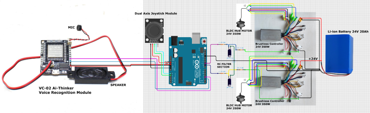
SCHEMATIC DIAGRAM
This is the complete schematic diagram of the proposed wheelchair system with Arduino UNO as the main controller supported by dual control options—voice and joystick mode. The system contains two powerful 24V 350-watt BLDC motors with two separate controllers for each motor, enabling precise and smoother motor control and operations. The system is energized using a 24V 20Ah rechargeable Li-ion battery pack module.
BLOCK DIAGRAM
PROGRAM
The below program is compiled and uploaded into Arduino UNO using Arduino IDE platform.
#include <SoftwareSerial.h>

/* ---------- THROTTLES ---------- */
#define LEFT_THROTTLE   9
#define RIGHT_THROTTLE 10

/* ---------- JOYSTICK ---------- */
#define JOY_X A0
#define JOY_Y A1

/* ---------- VOICE ---------- */
#define VC_RX 2
#define VC_TX 3

/* ---------- ULTRASONIC ---------- */
#define TRIG1 4
#define ECHO1 5
#define TRIG2 6
#define ECHO2 7
#define BUZZER 8

/* ---------- PWM ---------- */
#define PWM_STOP   0
#define PWM_RUN    140
#define PWM_TURN   140

/* ---------- VOICE COMMANDS ---------- */
#define CMD_FORWARD  0xA190
#define CMD_RIGHT    0xA192
#define CMD_LEFT     0xA193
#define CMD_STOP     0xA194

SoftwareSerial voice(VC_RX, VC_TX);

/* ---------- STATES ---------- */
enum State {
  STATE_CENTER,
  STATE_STOP,
  STATE_FORWARD,
  STATE_LEFT,
  STATE_RIGHT
};

State currentState = STATE_STOP;
State lastState    = STATE_STOP;

/* ---------- ULTRA VARIABLES ---------- */
float distance1 = 999, distance2 = 999;
long duration;

/* ---------- TIMING VARIABLES ---------- */
unsigned long lastVoiceTime = 0;
unsigned long forwardStartTime = 0;   //

/* ===================================================== */
float getDistance(int trigPin, int echoPin) {

  digitalWrite(trigPin, LOW);
  delayMicroseconds(2);

  digitalWrite(trigPin, HIGH);
  delayMicroseconds(10);
  digitalWrite(trigPin, LOW);

  duration = pulseIn(echoPin, HIGH, 25000);

  if (duration == 0) return 999;

  float dist = duration * 0.034 / 2;
  return dist;
}
/* ===================================================== */

void setup() {
  Serial.begin(9600);
  voice.begin(9600);

  pinMode(LEFT_THROTTLE, OUTPUT);
  pinMode(RIGHT_THROTTLE, OUTPUT);

  pinMode(TRIG1, OUTPUT);
  pinMode(ECHO1, INPUT);
  pinMode(TRIG2, OUTPUT);
  pinMode(ECHO2, INPUT);

  pinMode(BUZZER, OUTPUT);

  stopMotors();
  Serial.println(" FINAL STABLE SYSTEM (GRACE FIX) ");
}

/* ===================================================== */

void loop() {

  Serial.println("\n================ LOOP START ================");

  /* ---------- ULTRASONIC SAFE WINDOW ---------- */
  bool skipUltra = (millis() - lastVoiceTime < 500);

  if (skipUltra) {
    Serial.println("ULTRA → SKIPPED (VOICE ACTIVE)");
    digitalWrite(BUZZER, LOW);
  } else {

    distance1 = getDistance(TRIG1, ECHO1);
    delay(60);  // prevent cross-talk
    distance2 = getDistance(TRIG2, ECHO2);

    Serial.print("ULTRA → S1: ");
    Serial.print(distance1);
    Serial.print(" cm | S2: ");
    Serial.print(distance2);
    Serial.println(" cm");

    bool valid1 = (distance1 > 5 && distance1 < 125);
    bool valid2 = (distance2 > 5 && distance2 < 125);

    bool obstacle = false;

    //  FORWARD with GRACE TIME
    if (currentState == STATE_FORWARD) {

      if (millis() - forwardStartTime > 800) {
        obstacle = (valid1 || valid2);
      } else {
        Serial.println("FORWARD GRACE PERIOD (NO CHECK)");
      }
    }

    //  LEFT / RIGHT (close only)
    else if (currentState == STATE_LEFT || currentState == STATE_RIGHT) {
      bool close1 = (distance1 > 5 && distance1 < 80);
      bool close2 = (distance2 > 5 && distance2 < 80);

      obstacle = (close1 || close2);
    }

    if (obstacle) {
      Serial.println("🚨 OBSTACLE DETECTED → FORCE STOP");

      digitalWrite(BUZZER, HIGH);
      currentState = STATE_STOP;
      applyState(currentState);

      Serial.println("==========================================");
      delay(120);
      return;
    } else {
      digitalWrite(BUZZER, LOW);
      Serial.println("SAFE → NO OBSTACLE");
    }
  }

  /* ---------- JOYSTICK ---------- */
  State joyState = readJoystick();

  /* ---------- VOICE ---------- */
  State voiceState = readVoice();

  /* ---------- DECISION ---------- */
  Serial.print("DECISION → ");

  if (voiceState != STATE_CENTER) {
    currentState = voiceState;
    Serial.println("VOICE COMMAND APPLIED");
  }
  else if (joyState == STATE_FORWARD ||
           joyState == STATE_LEFT ||
           joyState == STATE_RIGHT ||
           joyState == STATE_STOP) {
    currentState = joyState;
    Serial.println("JOYSTICK COMMAND APPLIED");
  }
  else {
    Serial.println("NO CHANGE (JOYSTICK CENTER)");
  }

  /* ---------- APPLY ---------- */
  if (currentState != lastState) {
    applyState(currentState);
    lastState = currentState;
  }

  Serial.println("==========================================");

  delay(120);
}

/* =====================================================
   JOYSTICK LOGIC
   ===================================================== */
State readJoystick() {

  int x = analogRead(JOY_X);
  int y = analogRead(JOY_Y);

  Serial.print("JOY → X: ");
  Serial.print(x);
  Serial.print("  Y: ");
  Serial.print(y);
  Serial.print("  => ");

  /* ========= CENTER ========= */
  // OLD (tight)
  if ((x >= 525 && x <= 530) &&
      (y >= 516 && y <= 522)) {
    Serial.println("CENTER");
    return STATE_CENTER;
  }

  // NEW (fine tuned)
  if ((x >= 520 && x <= 540) &&
      (y >= 500 && y <= 540)) {
    Serial.println("CENTER (FT)");
    return STATE_CENTER;
  }

  /* ========= STOP (BACK) ========= */
  // OLD
  if (x <= 10 && (y >= 150 && y <= 550)) {
    Serial.println("STOP");
    return STATE_STOP;
  }

  // NEW (fine tuned)
  if (x <= 20) {
    Serial.println("STOP (FT)");
    return STATE_STOP;
  }

  /* ========= FORWARD ========= */
  // OLD
  if ((x >= 1020 && x <= 1023) &&
      (y >= 516 && y <= 522)) {
    Serial.println("FORWARD");
    return STATE_FORWARD;
  }

  // NEW (fine tuned based on your data)
  if ((x >= 1000) &&
      ((y >= 100 && y <= 130) ||     // lower band
       (y >= 500 && y <= 550) ||     // center band
       (y >= 650 && y <= 700))) {    // upper band
    Serial.println("FORWARD (FT)");
    return STATE_FORWARD;
  }

  /* ========= LEFT ========= */
  // OLD
  if ((x >= 525 && x <= 535) && y <= 10) {
    Serial.println("LEFT");
    return STATE_LEFT;
  }

  // NEW (fine tuned)
  if ((x >= 500 && x <= 1000) && y <= 20) {
    Serial.println("LEFT (FT)");
    return STATE_LEFT;
  }

  /* ========= RIGHT ========= */
  // OLD
  if ((x >= 525 && x <= 535) && y >= 1015) {
    Serial.println("RIGHT");
    return STATE_RIGHT;
  }

  // NEW (fine tuned)
  if ((x >= 500 && x <= 1000) && y >= 1000) {
    Serial.println("RIGHT (FT)");
    return STATE_RIGHT;
  }

  Serial.println("CENTER");
  return STATE_CENTER;
}

/* =====================================================
   VOICE LOGIC
   ===================================================== */
State readVoice() {

  if (voice.available() < 2) {
    Serial.println("VOICE → No command");
    return STATE_CENTER;
  }

  uint16_t cmd = (voice.read() << 8) | voice.read();
  flushVoiceBuffer();

  lastVoiceTime = millis();

  Serial.print("VOICE → CMD: 0x");
  Serial.println(cmd, HEX);

  if (cmd == CMD_FORWARD) {
    forwardStartTime = millis();   //  GRACE TIMER SET
    return STATE_FORWARD;
  }

  if (cmd == CMD_LEFT)  return STATE_LEFT;
  if (cmd == CMD_RIGHT) return STATE_RIGHT;
  if (cmd == CMD_STOP)  return STATE_STOP;

  return STATE_CENTER;
}

/* =====================================================
   MOTOR ACTIONS
   ===================================================== */
void stopMotors() {
  analogWrite(LEFT_THROTTLE, PWM_STOP);
  analogWrite(RIGHT_THROTTLE, PWM_STOP);
}

void forward() {
  analogWrite(LEFT_THROTTLE, PWM_RUN);
  analogWrite(RIGHT_THROTTLE, PWM_RUN);
}

void left() {
  analogWrite(LEFT_THROTTLE, PWM_STOP);
  analogWrite(RIGHT_THROTTLE, PWM_TURN);
}

void right() {
  analogWrite(LEFT_THROTTLE, PWM_TURN);
  analogWrite(RIGHT_THROTTLE, PWM_STOP);
}

void applyState(State s) {

  Serial.print("STATE → ");

  switch (s) {

    case STATE_STOP:
      Serial.println("STOP");
      stopMotors();
      break;

    case STATE_FORWARD:
      Serial.println("FORWARD");
      forward();
      break;

    case STATE_LEFT:
      Serial.println("LEFT");
      left();
      break;

    case STATE_RIGHT:
      Serial.println("RIGHT");
      right();
      break;

    case STATE_CENTER:
      Serial.println("CENTER");
      stopMotors();
      break;
  }
}

/* ===================================================== */
void flushVoiceBuffer() {
  while (voice.available()) voice.read();
}
Step 4 – BLDC Motor Control using Arduino PWM Signal - Testing Phase
- The 24V 350W BLDC motor controllers require an analog throttle signal for speed control. Instead of using a conventional e-bike throttle, the Arduino UNO generates a PWM signal based on joystick and voice command inputs.
- To convert the PWM signal into a stable analog voltage, an RC Low-Pass Filter was implemented using a resistor and capacitor network. The filtered analog voltage was then connected to the throttle input of the BLDC motor controller.
- This approach enabled the Arduino to electronically simulate a throttle signal and control the speed and direction of both hub motors during testing and final operation.
This video demonstrates the controlling of BLDC Hub motor with the help of a brushless controller and an Arduino UNO instead of an e-bike throttler.
Step 5 – Retrofitted Wheelchair Assembly and Testing Phase
After validating the individual subsystems, all components were integrated onto the wheelchair platform. The BLDC hub motors, motor controllers, battery pack, Arduino-based control units, joystick module, voice recognition module, ultrasonic sensors, and pressure monitoring system were mounted and interconnected.
The wheelchair was then tested under real operating conditions to verify system functionality and component integration. During this phase, joystick-based navigation and offline voice commands were used to control the wheelchair's movement. The response of the BLDC hub motors, steering performance, speed control, and overall system behavior were evaluated.
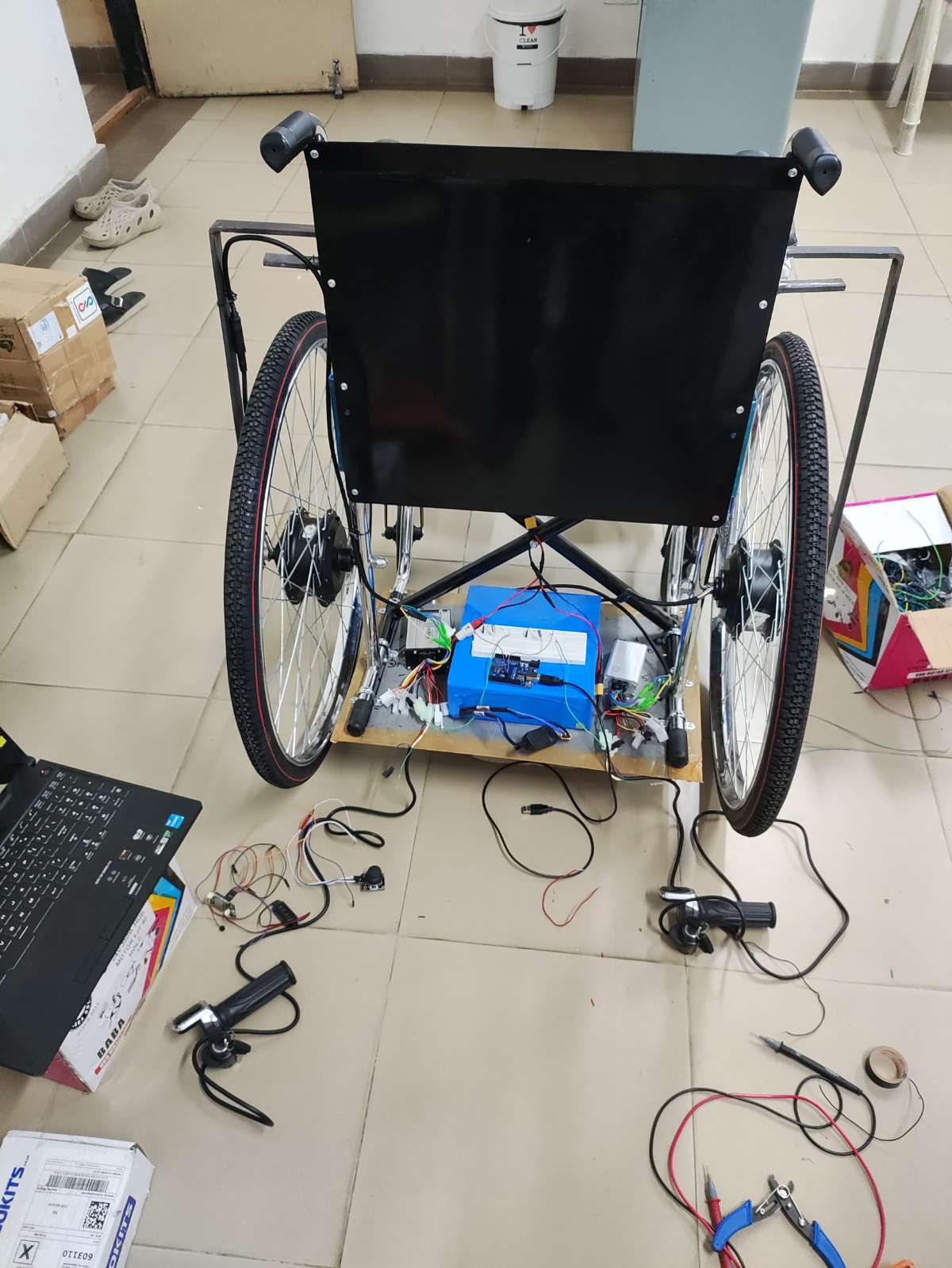
This testing phase confirmed the successful operation of the retrofitted smart wheelchair and validated the integration of the dual-control system prior to final implementation.
Step 6 – Obstacle Detection and Safety System
Two HC-SR04 ultrasonic sensors were installed at the front of the wheelchair. The sensors continuously monitor nearby obstacles and provide an additional safety layer by detecting objects in the wheelchair's path during movement.
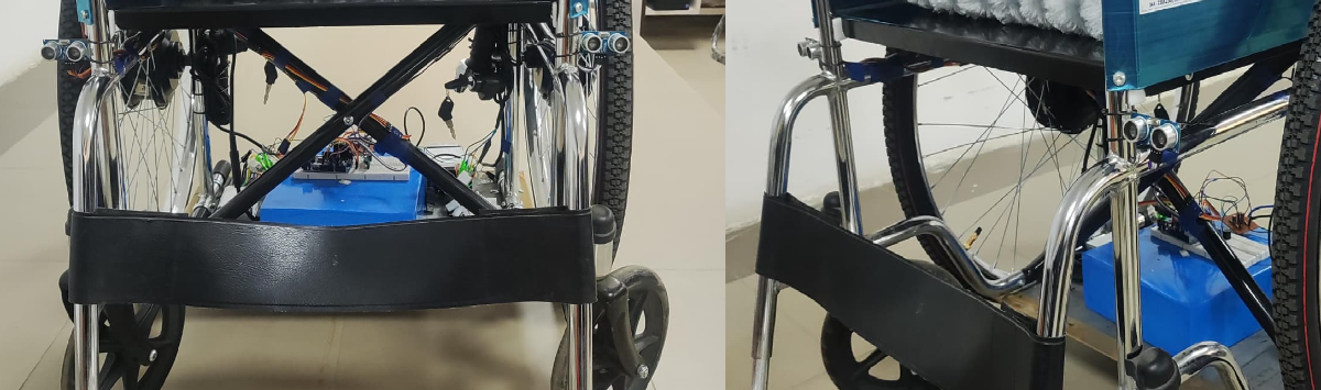
Step 7 – Pressure Monitoring System
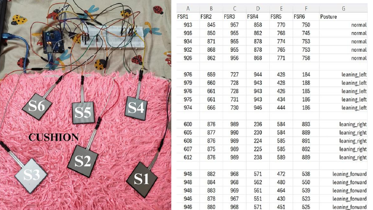
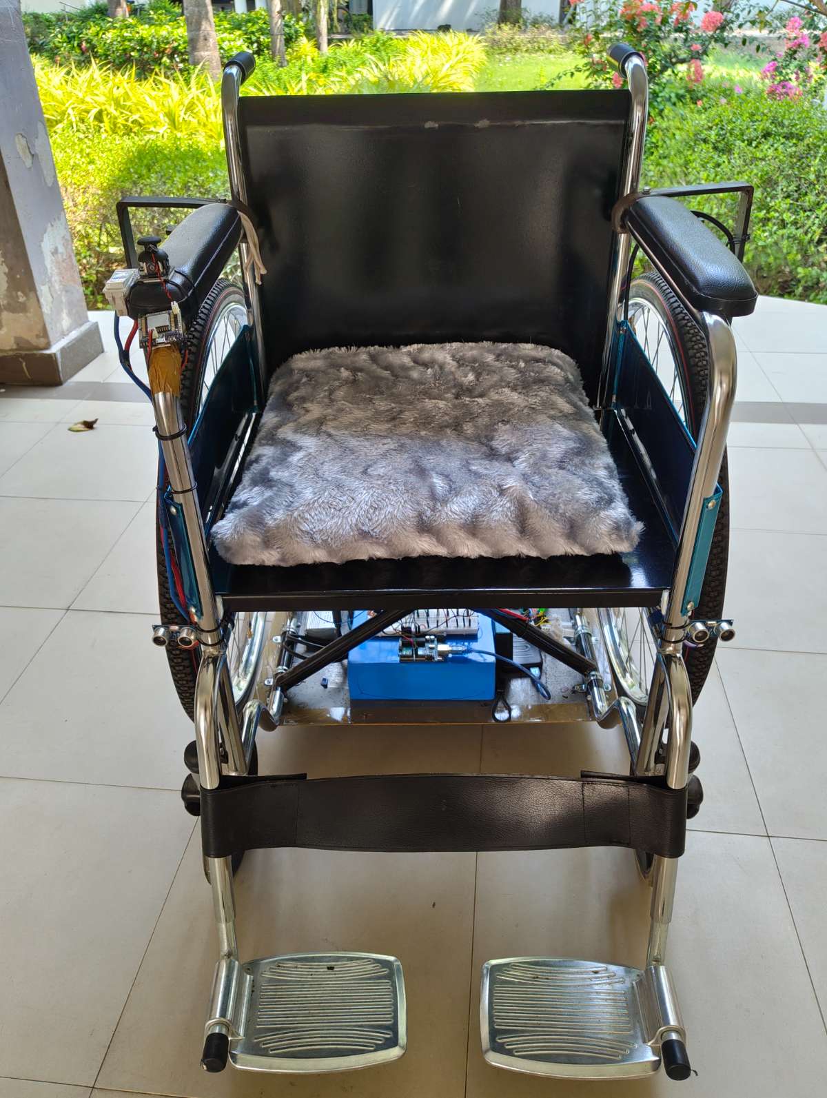
A separate Arduino UNO was dedicated to pressure monitoring. Six FSR-406 sensors were strategically placed inside the wheelchair seat cushion to measure pressure distribution across the seating surface. The system continuously monitors the user's posture and identifies prolonged leaning conditions that may lead to pressure ulcers. This figure shows the pressure monitoring cushion prototype and 6x FSR-406 sensor readings for various postures such as normal, leaning left, leaning right, and leaning forward.
- BLOCK DIAGRAM
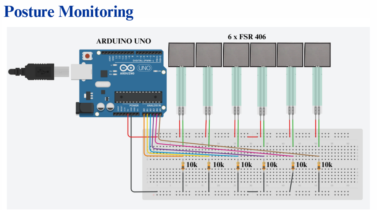
- SCHEMATIC DIAGRAM
PROGRAM
// -------- FSR Posture Detection --------
// Sensor mapping based on user's wiring:
// A0=S1, A1=S2, A2=S3, A3=S4, A4=S5, A5=S6

const int fsrPins[6] = {A0, A1, A2, A3, A4, A5};  // Correct order
int fsrValues[6];

const int THRESHOLD_DIFF = 700;  // Adjust during calibration

// ⭐ NEW — LED & Buzzer pins
#define GREEN_LED 8
#define RED_LED   9
#define BUZZER    7

// ⭐ NEW — Posture duration tracking
unsigned long postureStartTime = 0;
String lastPosture = "normal";
const unsigned long WARNING_TIME = 10000; // 10 seconds for testing purpose
void setup() {
  Serial.begin(9600);
  Serial.println("FSR Posture Detection Started...");

  pinMode(GREEN_LED, OUTPUT);
  pinMode(RED_LED, OUTPUT);
  pinMode(BUZZER, OUTPUT);
}

void loop() {

  //  Read all 6 sensors
  for (int i = 0; i < 6; i++) {
    fsrValues[i] = analogRead(fsrPins[i]);   // 0–1023
  }

  //  Compute group sums
  int leftSum  = fsrValues[0] + fsrValues[3];  // S1 + S4
  int midSum   = fsrValues[1] + fsrValues[4];  // S2 + S5
  int rightSum = fsrValues[2] + fsrValues[5];  // S3 + S6

  int frontSum = fsrValues[0] + fsrValues[1] + fsrValues[2];  // S1 + S2 + S3
  int backSum  = fsrValues[3] + fsrValues[4] + fsrValues[5];  // S4 + S5 + S6

  //  Decide posture
  const char* posture = "normal";

  if (abs(leftSum - rightSum) > THRESHOLD_DIFF) {
    posture = (leftSum > rightSum) ? "leaning_left" : "leaning_right";
  }
  else if (abs(frontSum - backSum) > THRESHOLD_DIFF) {
    posture = (frontSum > backSum) ? "leaning_forward" : "leaning_backward";
  }

  //  Print output in CSV format:
  // S1,S2,S3,S4,S5,S6,posture
  for (int i = 0; i < 6; i++) {
    Serial.print(fsrValues[i]);
    Serial.print(",");
  }
  Serial.println(posture);

  // NEW — LED + Buzzer logic based on prolonged wrong posture
  if (String(posture) != lastPosture) {
    lastPosture = posture;
    postureStartTime = millis();         // reset timer when posture changes
  }

  if (String(posture) != "normal") {
    if (millis() - postureStartTime > WARNING_TIME) {   // >10 sec wrong posture
      digitalWrite(RED_LED, HIGH);
      digitalWrite(GREEN_LED, LOW);
      digitalWrite(BUZZER, HIGH);
    } else {                                            // wrong posture but <10 sec
      digitalWrite(RED_LED, LOW);
      digitalWrite(GREEN_LED, HIGH);
      digitalWrite(BUZZER, LOW);
    }
  } else {                                              // normal posture
    digitalWrite(GREEN_LED, HIGH);
    digitalWrite(RED_LED, LOW);
    digitalWrite(BUZZER, LOW);
  }

  delay(300);   // ~3 readings per second
}
FSR Sensor Working Principle
The FSR (Force Sensitive Resistor) changes its resistance according to the applied force. A voltage divider circuit with a 10kΩ resistor converts the resistance variation into a measurable voltage signal for the Arduino.
Pressure = Force / Area
Output Voltage: Vo = Vcc × (R / (R + FSR))
As pressure increases, the sensor resistance decreases, resulting in a corresponding change in output voltage.
.png)
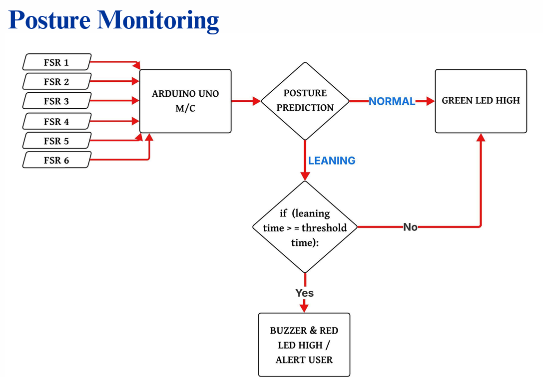
The six FSR sensor readings are continuously analyzed to determine the user's sitting posture.
- Normal posture → Green LED indication
- Leaning posture detected → Timer starts
- Leaning beyond threshold duration → Buzzer and Red LED activated
This helps alert the user before prolonged pressure concentration can develop into pressure ulcers or bedsores.
Posture Monitoring Demo
- This demonstration shows the posture monitoring system of the Smart E-Wheelchair.
- Six FSR-406 sensors embedded inside the seat cushion continuously monitor the user's pressure distribution.
- During normal sitting posture, the green LED remains ON and no alert is generated.
- When the user leans left, right, and forward. The Arduino detects the pressure imbalance and continuously monitors the posture.
- For demonstration purposes, the alert threshold is set to 5 seconds. If the leaning posture persists beyond this duration, the red LED and buzzer are activated to alert the user.
- In actual wheelchair usage, this threshold can be increased to around 30 minutes to help prevent prolonged pressure concentration and reduce the risk of pressure ulcers.
Final Result
Both subsystems were integrated into a single smart wheelchair platform:
- Wheelchair Control Module
- Voice Control
- Joystick Control
- Obstacle Detection and Avoidance
- Health Monitoring Module
- FSR Pressure Monitoring
- Posture Detection
- Alert Generation
.png)
Final Testing and Validation
The completed wheelchair was tested for the following:
- Movement and turning of wheelchair
- Offline voice command recognition
- Joystick navigation
- Obstacle detection and avoidance
- Pressure monitoring and posture alerts
The final prototype successfully achieved dual-control wheelchair operation with integrated pressure monitoring, improving user mobility, safety, comfort, and independence.
CHAKRA - Smart E-Wheelchair complete setup
Wheelchair movement control using Voice module - Demonstration
Wheelchair movement control using Joystick module - Demonstration
Obstacle Detection & Avoidance - Demonstration
Ramp Test of CHAKRA - Smart E-Wheelchair