
EQUIPMENT'S REQUIRED
- Raspberry Pi 4 Model B:- It was released in June 2019 with a 1.5 GHz 64-bit quad core ARM Cortex-A72 processor, on-board 802.11ac Wi-Fi, Bluetooth 5, full gigabit Ethernet (throughput not limited), two USB 2.0 ports, two USB 3.0 ports, 2-8 GB of RAM, and dual-monitor support via a pair of micro-HDMI (HDMI Type D) ports for up to 4K resolution. The Pi 4 is also powered via a USB-C port, enabling additional power to be provided to downstream peripherals, when used with an appropriate PSU. But the Pi can only be operated with 5 volts.
(2).jpg)
- Camera:- It is the necessity after the microcontroller board for this project. The system uses the normal high resolution surveillance cameras that we find nowadays in homes for surveillance. Wireless cameras can also be brought into consideration as per the requirements in context to the place.
(0).jpg)
- MQ-2 Sensor (Methane, Butane, LPG, smoke):- It is an electronic sensor used for sensing the concentration of gases in the air such as LPG, propane, methane, hydrogen, alcohol, smoke and carbon monoxide. MQ-2 gas sensor is also known as chemi-resistor. MQ-2 is a metal oxide semiconductor type gas sensor. Concentrations of gas in the gas is measured using a voltage divider network present in the sensor. This sensor works on 5V DC voltage. It can detect gases in the concentration of range 200 to 10000ppm. MOS sensors measure the change in resistance when gases are present. This type of sensor requires the gas to encounter the sensor for a chemical reaction to occur. This chemical reaction causes a change in resistance, which is then measured to detect the presence or concentration of the gas. However, the MQ 2 sensor is not specific towards one gas. Therefore, a calculated concentration of gas may not accurately represent the mixture in the air. The mechanism to sensing the change in resistance lies within the structure of the sensor. The MQ 2 sensor contains an anti-explosion network. This is particularly important due to the heating element inside the sensor and its potential contact with a flammable gas. This network is composed of two layers of stainless-steel mesh. This mesh also functions to filter our particulates from contaminating and dirtying the sensing mechanism. The mesh is mounted to a Bakelite base. Bakelite is a thermo-setting plastic made from phenol and formaldehyde. It does not change shape and will not melt under heat, therefore, providing a very stable base for the sensor to rest. The sensing mechanism is under the anti-explosion mesh and is connected to six legs. It is constructed of aluminum oxide (Al2O3) based ceramic and coated with tin dioxide (SnO2) – acts as the gas sensing layer - to form a ceramic tube. Inside this ceramic tube is a nickel-chromium heating coil (Ni-Cr). The Ni-Cr coil is connected to two of the six legs surrounding the tube. The other four legs, composed of platinum wires, send the small changing currents as output signals from the sensor. In summary, the Ni-Cr coil and the Al2O3 form a heating system to make sure the sensor is at working temperature and the platinum wires and SnO2 form the sensing system. When the gas interacts with the sensor, the heat from the system ionizes the gas. This ionization allows SnO2 to absorb the gas. This adsorption causes a change in the resistance on the sensor. The output legs then send this resistance as an output signal to the microcontroller.
.jpg)
- Relay:- A relay is an electrical main voltage switch. This means that it can be turned on or off, letting the current flow or not. Controlling a relay with raspberry pie is as simple as controlling an output like a motor. There are many types of modules, such as single channels, double channels, four channels and eight channels. A type of relay able to handle the high power required to directly control an electric motor or other loads called contractors. Relays with calibrated operating characteristics and sometimes multiple operating coils are used to protect electrical circuits from overloads or failures. In relation to the mains voltage, the relays have 3 possible connections. There is a common pin (COM), usually a pin (NO) and a normally closed pin (NC). There is no contact between the common pin and the normally open (NO) pin. We activate the relay to connect the COM pin and the power supply is supplied to a load. There is a contact between the COM pin and the NC pin. A connection between the COM and NC pins is always required, even when the relay is switched off. When we activate the relay, the circuit opens and there is no power supply for a load.
.jpg)
CALCULATIONS
The concentration (ppm) of gases is calculated based of the resistance ratio (RS/R0). RS is the measured change in resistance when the sensing mechanism detects gas and R0 is the stable sensor resistance in fresh air or no gas presence. Using Ohm’s law and the sensor schematic :-
RS = (V C − RL)/V out − RL
VC is the voltage current (in this case 5V from the pi), Vout is the output voltage (measured analog/digital value), and RL is the load resistance (this set up is at 10K). R0 can then be calculated using this equation:- R0 = RS/Fresh air ratio value from datasheet.
In order to convert the digital signal to concentration units, the datasheet chart is used again. A simple calibration line has y = mx + b, however, the MQ-2 gas sensor is not linear. It follows a log-log scale so a bit more calculation is needed. So the y = mx + b equation can be converted to log(y) = m ∗ log(x) + b.
Now using the chart, the slope and intercept can be calculated. 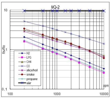
Where
m = log(y/y0)/log(x/x0)
b = log(y) − m ∗ log(x)
Once these values are obtained, the concentration of gas can now be calculated as:
x(ppm) = 10[log (y )−b]/m
Now, Calculating for LPG. At 1000ppm the values are (1000,0.8) and at 10000ppmthe values are (10000, 0.27).
m = log(0.27/0.8)/log(10000/1000) = 0.47
b = log(0.8) + 0.47 ∗ log(1000) = 1.31
PROGRAMMING
- First import the required python libraries.
import cv2
import NumPy
import smtplib
import model
- Then configure the camera used for fire detection and face recognition
cap = cv2.VideoCapture(0)
- Then we use the cascade files for imparting accuracy and proper functioning to the given system.
face cascade = cv2.CascadeClassifier (’haarcascade frontal face default.xml’)
fire cascade= cv2.CascadeClassifier(’fire.xml’)
- Configuring the smtp server for sending messages to the user in the undesired situation.
account Sid = ”
auth token = ”
client = Client(account Sid, auth token)
Sender Email = ””
Receiver Email = ””
f = open(”password”, ”r”)
Password= f.read()
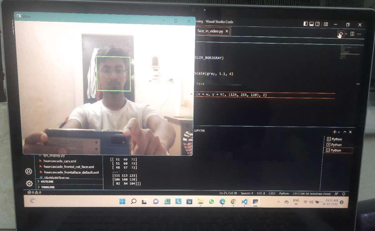
- Writing the program for face recognition.
cv2.rectangle(img, (x, y), (x + w, y + h), (124, 255, 0),2)Roi color = gray [y:y+h, x:x+w]
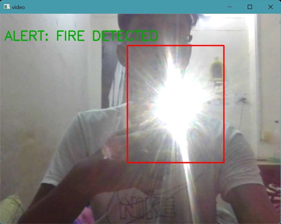
- Writing the program for fire detection.
cv2.rectangle(frame1, (x-20, y-20), (x + w + 20, y + h + 20), (0, 0, 255), 2)
cv2.putText(frame1,”ALERT:()”.format(”FIRE DETECTED ”), (10, 40), cv2.FONTHERSHEY SIMPLEX, 1, (217, 10, 10), 2)
- Writing the program for motion detection.
ret, frame1 = cap.read()
ret, frame2 = cap.read()
(-, img) = cap.read()
diff = cv2.absdiff(frame1, frame2)
diff gray = cv2.cvtColor(diff, cv2.COLOR BGR2GRAY)
blur = cv2.GaussianBlur(diff gray, (5, 5), 0)
(-, thresh) = cv2.threshold(blur, 20, 255, cv2.THRESH BINARY)
dilated = cv2.dilate(thresh, None, iterations=3)
contours, - = cv2.findContours(dilated, cv2.RETRTREE, cv2.CHAIN APPROX SIMPLE)
- Combining these programs such that all of them work parallel without creating any disruptions.
- Training a model comprising the faces of user and his family. The model was trained using keras and multiple image sets were used to develop the model and increase its accuracy. The final accuracy recorded after training the model ranged to 81.2%.
- After successful training of the model, we must import the model to our program. The trained model will be used to distinguish the user and his registered members from intruders.
- Configuring the gas sensor.
import time
import math
from gpiozero import MCP3008
adc0 = MCP3008(channel=0)
sensor value = 0
x = 0
for x in range (0,500)
sensor value = sensor value + adc1.value
x = x+1
sensor value1 = sensor value/500
Rsair = ((3.3*10)/sensor volt)-10
R0 = Rsair/9.9
while True:
LPGm = -0.47
LPGb = 1.31
sensor value = adc1.value
RSgas = ((3.3*10)/sensor volt)-10
ratio1 = (RSgas/R0)
ratio = math.log10(ratio1)
LPGratio = (ratio-LPGb)/LPGm
LPGppm = math.pow(10,LPGratio)
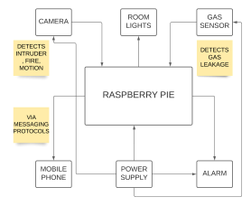
LPGperc= LPGppm/10000BLOCK DIAGRAM
Applying logic for how the system must work.
CIRCUIT DIAGRAM
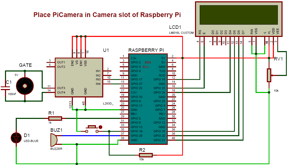
WORKING
The system will be working in live conditions. The installed camera has been programmed for fire, motion and intruder detection. In accordance with which a gas sensor has been used to detect gas leakage. Also, a trained model has been applied comprising the faces of people registered by the user. Firm connections are made including the alarm and relay that has the purpose to alert the user and control the lights in case of inactive sessions within the room. A regular power supply is also embedded to the system which will be powering the installed microcontroller board, sensors, alarm along with the camera. Now the system will be functioning as a general camera under normal circumstances. It will be streaming the live video to the user. But as soon as the scenario changes and it detects an unusual activity such as a stranger in the house then the system will come into action. It will first be extracting the image of the stranger and then will be matching the image with the imported model. If the image matches with the model, then the system will return to its normal mode other in case the image doesn’t matches with the model then it will perform the action of alerting the user. It will send an alert message to the user along with the stranger pictures. Seeing this the user will be alerted. On the other hand, if the system detects fire or gas leakage it will again alert the user via a message also in this case the alarm will be turned on and hence the user can be made aware of the situation. Third part of the system deals with power saving using motion detection features. In this busy world people have developed a tendency to leave the lights on while moving out of the room. Hence under such conditions the camera will be detecting no motion inside the room and will turn off the lights and appliances automatically. There will be a short time limit after which the motion detection feature will come into action. It will not operate as soon as the user leaves the room but there will be a certain time period feed to the microcontroller after which it will take the desired action.
MODIFICATIONS
A first step never always leads to a perfect thing but as the time passes several modifications are done for the betterment of the product. In this regard the proposed system can also undergo modifications in the coming times. Some ideas to where we could think of modification includes improving the accuracy of the model so that the system becomes more accurate, another point which comes into consideration is installing some more automated features that would increase the security rate of the system. Installing automatic water showers for getting rid of fire incidents and keeping the power supply off during gas incidents can be taken care off to avoid any damage to life and property.
APPLICATIONS
The system is best suited to be used in homes, hotels, labs where safety is the major concern. It contains features that are highly desirable in such areas. Also, it could be used in gas plants and mines where incidents of fire and gas leakage have grown a pace in the recent times. It will reduce the risk factor to a very low extent as the workers and engineers working in such places could be made aware prior to any unusual happenings. The system could be installed in forests after much modification to get rid of fire accidents and smugglers hence protecting the wildlife and biodiversity. Installing the system at airports to trace criminals departing from the country could be a major application. The system will be tracing them and will inform the airport authority at a sudden so that any such criminal could not leave the country, State or City.
CONCLUSION
A user-friendly, easy to install and low-cost system that has advance features for safety and surveillance. It ensures safety against intruders, fire and gas leakages. A feature of it also deals with power saving. The system is cheap and can easily be installed by the user. Such systems would increase the overall safety and provide security from intruders.
REFERENCES
- Face Recognition Homepage, http://www.face-rec.org/algorithms/
- OpenCV Homepage, http://opencv.willowgarage.com
- Computer Vision Papers, http://www.cvpapers.com/
- Wikipedia, Active appearance model http://en.wikipedia.org/wiki/Active-appe-arance-model
- Arduino Playground - MQ Gas Sensorshttps://playground.arduino.cc/Main/MQGasSensors.
- EngineersGarage. Insight- Learn the Working of a Gas Sensor https://www.engineersgarage.com/insight/how-gas-sensor-works.
- J. Seebamrungsat, S. Praising and P. Riyamongkol, Fire Detection in the Buildings Using Image Processing, 2014.