

E-MEASURE AUTOMATION
Introduction
The "Smart Energy Meter Monitoring System" and the "Energy Meter Monitoring System" both aim to enhance the monitoring and management of energy consumption, leveraging cloud-based technology, mobile applications, and real-time alerts to provide users with detailed insights and control over their energy usage. Key components of both systems include energy meters, data communication modules, microcontrollers for data processing, and interfaces for remote monitoring and control. They both support emergency notifications, helping prevent electrical faults and ensuring safety.
Energy Meter Monitoring System
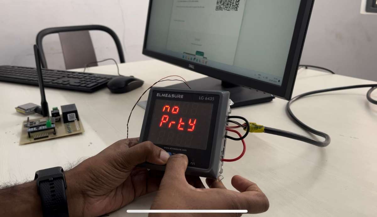
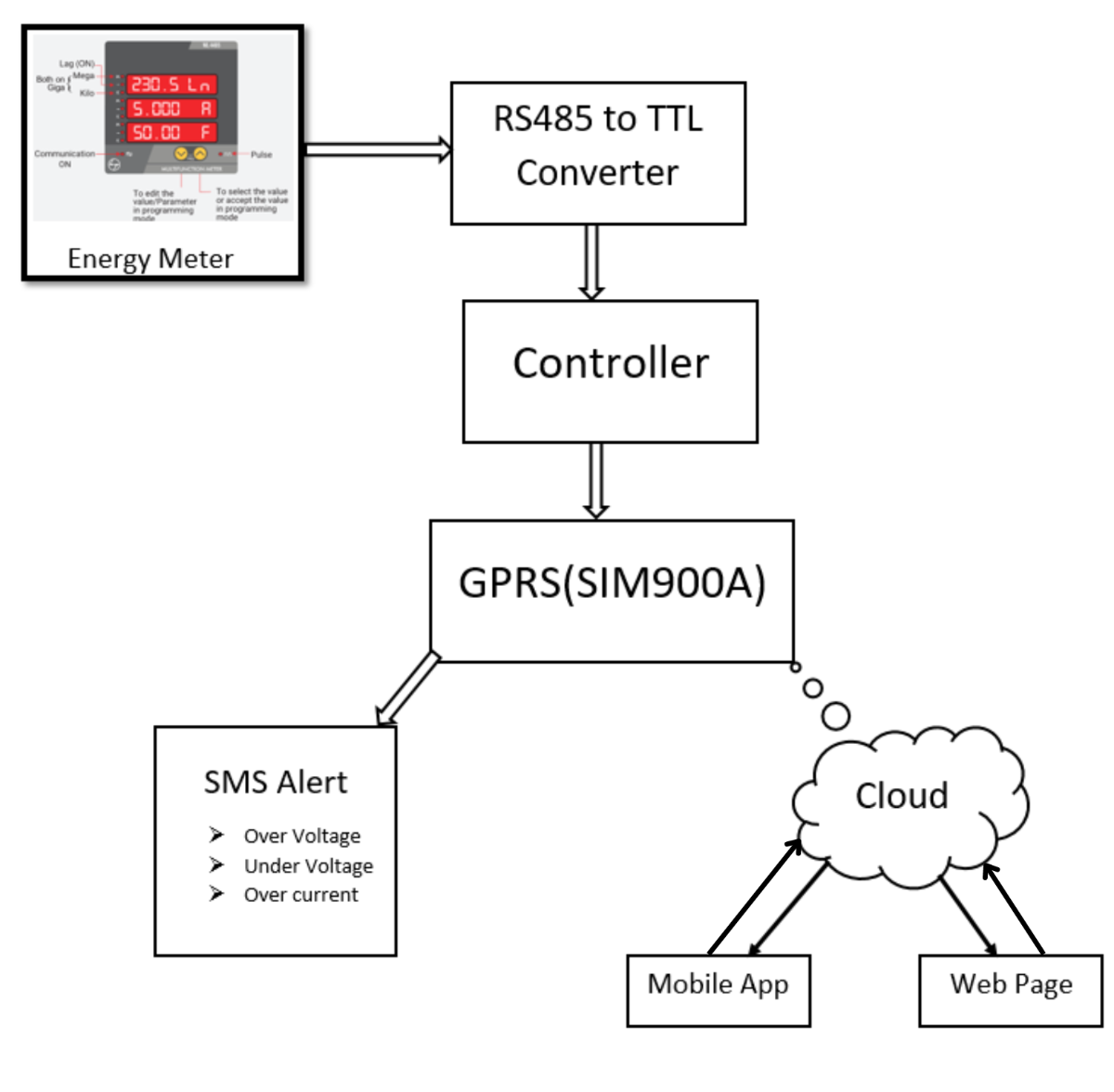
The "Energy Meter Monitoring System" focuses on real-time monitoring of 3-phase energy consumption using an LG 6435P energy meter and an RS485 to TTL converter. It displays data on a cloud-based webpage and mobile application and sends SMS alerts for overvoltage, undervoltage, and overcurrent. Users can set voltage and current thresholds via app and webpage interfaces.
Key Features:
Real-time Monitoring and Control
1) Comprehensive Monitoring: Monitors 28 electrical parameters, including voltage, current, power, and energy consumption.
2) Reliable Data Communication: Utilizes MODBUS RTU over RS485 for accurate and reliable data transmission.
3) High Current Control: Includes a relay to prevent overloading and manage high current loads effectively.
Remote Access and Alerts:
4) Cloud Storage and Mobile App: Provides remote access to real-time data and historical records through cloud storage and a mobile app.
(0).jpeg)
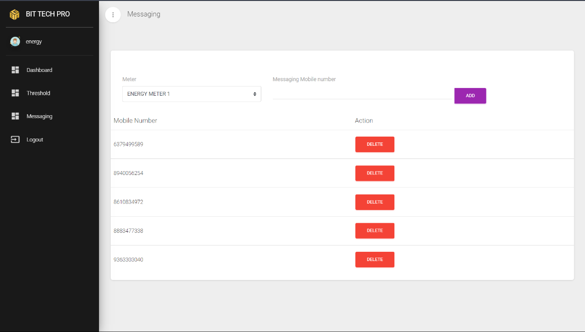
5) SMS Notifications: Uses a GSM module to send real-time SMS alerts for critical events or emergencies.
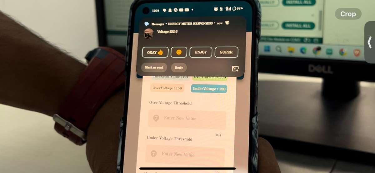
6) User-Configurable Settings: Allows customization of voltage and current thresholds to meet specific requirement
.jpeg)
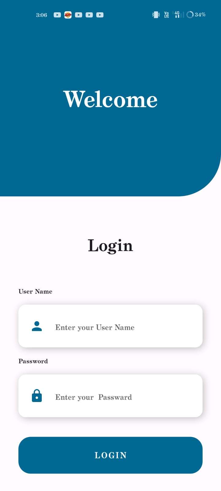
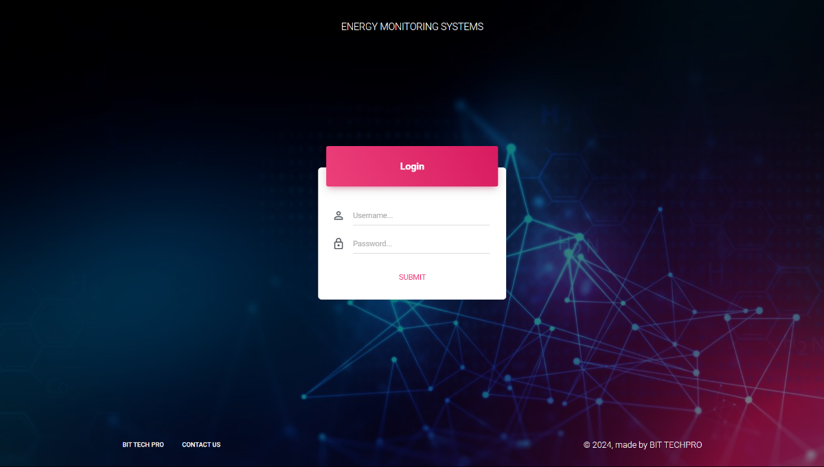
7) Secure Login: Ensures authorized access to the system, enhancing security and data protection.
Power Management and Scalability:
8) Power Conversion: Features an HYLink power module for stable DC voltage supply, ensuring consistent performance.
9) Scalability: Can be scaled to monitor multiple energy meters on a panel board, making it suitable for larger systems.
Advanced Design and Cloud Integration:
10)Cloud Services: Uses AWS Cloud for data storage and management, ensuring robust and scalable cloud infrastructure.
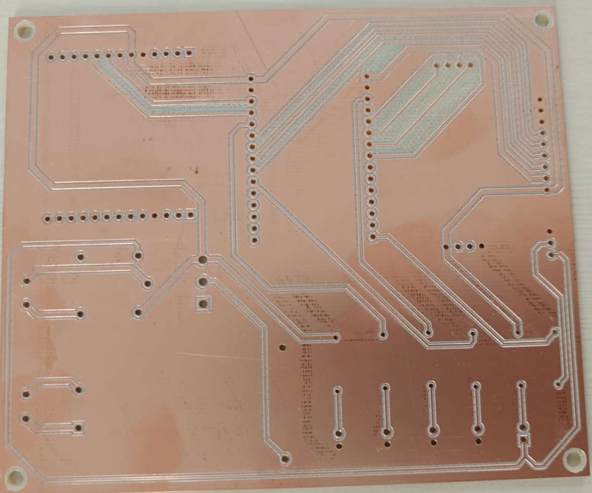
11) PCB Design: Utilizes Altium for professional PCB design, ensuring reliability and efficiency in the hardware layout.
Components Overview
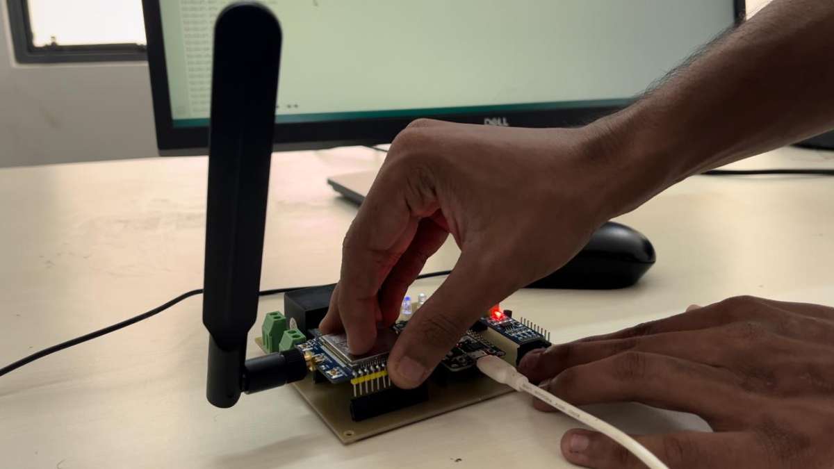
ESP32 DevKitC 32E:
Description: The ESP32 DevKitC 32E is a development board based on the ESP32-WROOM-32E module. It features dual-core processing capabilities and integrates Wi-Fi and Bluetooth connectivity.
Key Features:
- Dual-core CPU
- Integrated Wi-Fi and Bluetooth
- Multiple GPIO pins
- ADC, DAC, UART, SPI, I2C, and PWM interfaces
Applications: Ideal for IoT applications, smart devices, and wireless communication projects
SIM7600G-H:
Description: The SIM7600G-H is a versatile 4G LTE module that includes GNSS capabilities for navigation and tracking.
Key Features:
- Supports LTE-TDD/LTE-FDD, WCDMA, and GSM
- Integrated GNSS for GPS and navigation
- Various internet and voice communication protocols
Applications: Suitable for cellular communication, GPS tracking, and remote data acquisition
LG 6435P Energy Meter:
Description: The LG 6435P is an electronic energy meter designed to measure electrical energy consumption with high accuracy.
Key Features:
- High measurement accuracy
- Supports multiple communication protocols, including RS485
- Measures various electrical parameters
Applications: Used in monitoring and managing electrical energy usage in residential, commercial, and industrial environments.
RS485 to TTL Converter:
Description: This converter translates RS485 signal levels to TTL levels, facilitating communication between devices that operate on different voltage standards.
Key Features:
- Bidirectional data transmission
- Supports long-distance communication
- Typically used to connect microcontrollers with RS485 devices
Applications: Essential for industrial automation, data acquisition systems, and integrating RS485 devices with TTL-based systems.
Relay:
Description: A relay is an electrically operated switch that provides isolation between the control circuit and the high-power load.
Key Features:
- Isolates control and power circuits
- Available in normally open (NO) or normally closed (NC) configurations
- Various voltage and current ratings
Applications: Utilized to control high-power devices like motors, lights, and appliances using low-power control signals from microcontrollers.
Hi-Link Power Module:
Description: Hi-Link power modules are compact AC-DC converters that provide regulated DC output from an AC input.
Key Features:
- Compact size with high efficiency
- Provides regulated DC output
- Available in various voltage and current ratings
Applications: Commonly used as power supplies for electronic circuits, particularly in IoT devices and embedded systems.
Implementation
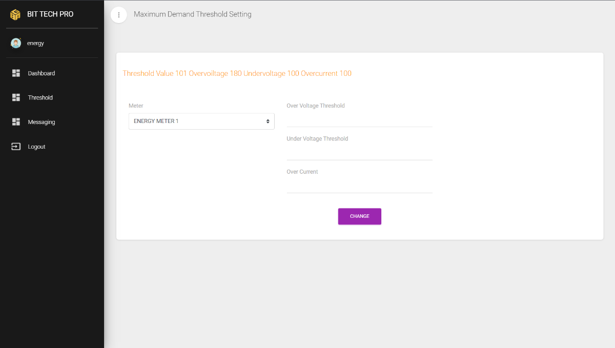
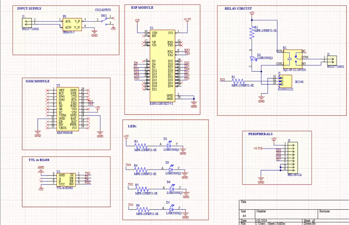
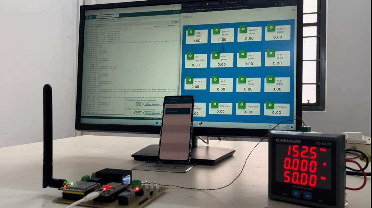
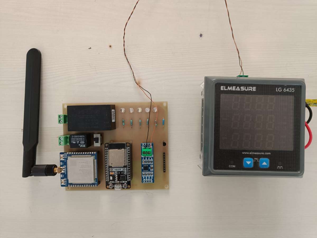
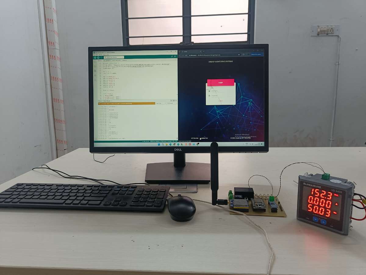
The system connects the LG 6435P energy meter to a microcontroller via the RS485 to TTL converter. The microcontroller reads data using the Modbus protocol, processes it, and sends it to the cloud server using GPRS connectivity. The cloud server hosts a webpage interface for monitoring parameters such as watts, power factor, volt-amperes, voltage, current, frequency, and energy consumption. The mobile application is developed using Flutter, providing a seamless experience on both iOS and Android platforms. Users can input their mobile numbers for receiving SMS alerts, and the system continuously monitors voltage and current values, triggering alerts when predefined thresholds are exceeded.
Schematic
PCB Design & 3D Views
Applications
This system is ideal for general use in monitoring 3-phase energy consumption for safety and efficiency.
Website
Smart Energy Meter Monitoring System
The "Smart Energy Meter Monitoring System" emphasizes real-time monitoring and management of energy consumption with the MODBUS RTU protocol over RS485, processed by an ESP32 microcontroller. It includes SMS notifications, high current control, and power conversion features to ensure safety and reliable power supply.
CODE:
String num1;
String num2;
String num3;
String num4;


#include "mb_getdata.h"
#include "push_data_int.h"
#include "values.h"

#include <EEPROM.h>

#include <ArduinoJson.h>
String number ="http://13.233.93.242/projects/energy/api/get-messaging-mobile-numbers.php?mid=101";
String data="http://13.233.93.242/projects/energy/api/get-max.php?mid=101";
JsonDocument doc;

int a, b, c;
const int X = 40001;

#define MAX485_DE 5
#define MAX485_RE_NEG 4
#define RX_PIN 16
#define TX_PIN 17
#define relay1 23
#define relay2 22
#define LED 25

bool st = false;

void setup() {
  pinMode(relay1, OUTPUT);
  pinMode(relay2, OUTPUT);
  pinMode(LED, OUTPUT);

  modbus_init(MAX485_RE_NEG, MAX485_DE, RX_PIN, TX_PIN);
  Serial.begin(9600);
  gprs_init(12, 13);
  String num_data = get_num();
  deserializeJson(doc, num_data);
  long long int temp;

  temp =doc["data"][0];
  num1 = "+91" + String(temp);

  temp =doc["data"][1];
  num2 = "+91" + String(temp);

  temp =doc["data"][2];
  num3 = "+91" + String(temp);

  temp =doc["data"][3];
  num4 = "+91" + String(temp);

  Serial.println(num1);
  Serial.println(num2);
  Serial.println(num3);
  Serial.println(num4);

  }

void loop() {
  digitalWrite(relay1,LOW);
  digitalWrite(relay2,LOW);
  digitalWrite(LED,LOW);

  String fgh = get_data();


  Serial.println();
  Serial.println(fgh);
  if (fgh != "{}") {
    deserializeJson(doc, fgh);
    a = doc["data"][0];
    b = doc["data"][1];
    c = doc["data"][2];
  }
MODBUS CONFIGURATION :
Serial.println(a);
  Serial.println(b);
  Serial.println(c);

  // get modbus values
  wattstot = modbus_read((40101 - X), 2);
  wattsrphase = modbus_read((40103 - X), 2);
  wattsyphase = modbus_read((40105 - X), 2);
  wattsbphase = modbus_read((40107 - X), 2);
  PFAverage = modbus_read((40117 - X), 2);
  pfrphase = modbus_read((40119 - X), 2);
  pfyphase = modbus_read((40121 - X), 2);
  pfbphase = modbus_read((40123 - X), 2);
  vatotal = modbus_read((40125 - X), 2);
  varphase = modbus_read((40127 - X), 2);
  vayphase = modbus_read((40129 - X), 2);
  vabphase = modbus_read((40131 - X), 2);
  VLLAverage = modbus_read((40133 - X), 2);
  vryphase = modbus_read((40135 - X), 2);
  vybphase = modbus_read((40137 - X), 2);
  vbrphase = modbus_read((40139 - X), 2);
  VLNAverage = modbus_read((40141 - X), 2);
  vrphase = modbus_read((40143 - X), 2);
  vyphase = modbus_read((40145 - X), 2);
  vbphase = modbus_read((40147 - X), 2);
  currenttotal = modbus_read((40149 - X), 2);
  currentrphase = modbus_read((40151 - X), 2);
  currentyphase = modbus_read((40153 - X), 2);
  currentbphase = modbus_read((40155 - X), 2);
  Frequency = modbus_read((40157 - X), 2);
  wh = modbus_read((40159 - X), 2);
  vah = modbus_read((40161 - X), 2);
  loadhours = modbus_read((40217 - X), 2);
MODBUS INITIALIZATION:
void modbus_init(byte RE, byte DE, byte Rx, byte Tx) {
  MAX485_RE_NEG = RE;
  MAX485_DE = DE;
  Serial1.begin(9600, SERIAL_8N1, Rx, Tx);
  pinMode(MAX485_RE_NEG, OUTPUT);
  pinMode(MAX485_DE, OUTPUT);
  digitalWrite(MAX485_RE_NEG, 0);
  digitalWrite(MAX485_DE, 0);
  node.begin(1, Serial1);
  node.preTransmission(preTransmission);
  node.postTransmission(postTransmission);
}
GPRS INITIALIZATION:
void gprs_init(byte rx_gprs, byte tx_gprs) {
  Serial2.begin(9600, SERIAL_8N1, rx_gprs, tx_gprs);
}
ALERT MESSAGE :
String str_values =
    String(wattstot) + "," + String(wattsrphase) + "," + String(wattsyphase) + "," + String(wattsbphase) + "," + String(PFAverage) + "," + String(pfrphase) + "," + String(pfyphase) + "," + String(pfbphase) + "," + String(vatotal) + "," + String(varphase) + "," + String(vayphase) + "," + String(vabphase) + "," + String(VLLAverage) + "," + String(vryphase) + "," + String(vybphase) + "," + String(vbrphase) + "," + String(VLNAverage) + "," + String(vrphase) + "," + String(vyphase) + "," + String(vbphase) + "," + String(currenttotal) + "," + String(currentrphase) + "," + String(currentyphase) + "," + String(currentbphase) + "," + String(Frequency) + "," + String(wh) + "," + String(vah) + "," + String(loadhours);

  Serial.print(str_values);

  put(str_values);

  Serial.println("VLL :" + String(VLLAverage));
  if (VLNAverage > 0) {
    if (!st) {
      message(num1, "power: ON");
      delay(1000);
      message(num2, "power: ON");
      delay(1000);
      message(num3, "power: ON");
      delay(1000);
      message(num4, "power: ON");
      delay(1000);
      st = true;
    }
  } else {
    if (st) {
      message(num1, "power: OFF");
      delay(1000);
      message(num2, "power: OFF");
      delay(1000);
      message(num3, "power: OFF");
      delay(1000);
      message(num4, "power: OFF");
      delay(1000);
      st = false;
    }
  }

  if (VLLAverage < b && VLLAverage > 0) {
    //less volt
    digitalWrite(relay1,HIGH);
    digitalWrite(LED,HIGH);
    message(num1, "voltage drop:volt = " + String(VLLAverage) + "V");
    delay(1000);
    message(num2, "voltage drop:volt = " + String(VLLAverage) + "V");
    delay(1000);
    message(num3, "voltage drop:volt = " + String(VLLAverage) + "V");
    delay(1000);
    message(num4, "voltage drop:volt = " + String(VLLAverage) + "V");
    delay(1000);
  }

  if (VLLAverage > a) {
    //more volt
    digitalWrite(relay1,HIGH);
    digitalWrite(LED,HIGH);
    message(num1, "High voltage \n volt = " + String(VLLAverage) + "V");
    delay(1000);
    message(num2, "High voltage \n volt = " + String(VLLAverage) + "V");
    delay(1000);
    message(num3, "High voltage \n volt = " + String(VLLAverage) + "V");
    delay(1000);
    message(num4, "High voltage \n volt = " + String(VLLAverage) + "V");
    delay(1000);
  }

  if (currenttotal > c) {
    //more current
    digitalWrite(relay2,HIGH);
    digitalWrite(LED,HIGH);
    message(num1, "The device have delivered high current \n current = " + String(currenttotal) + "A");
    delay(1000);
    message(num2, "The device have delivered high current \n current = " + String(currenttotal) + "A");
    delay(1000);
    message(num3, "The device have delivered high current \n current = " + String(currenttotal) + "A");
    delay(1000);
    message(num4, "The device have delivered high current \n current = " + String(currenttotal) + "A");
    delay(1000);
  }
}
How It Works:
MESSAGE ALERT CODE:
The system continuously measures electrical parameters, providing up-to-date data to help users track energy usage and identify inefficiencies. It converts data from RS485 to TTL levels for processing by the ESP32 microcontroller and prepares it for transmission to the cloud and for SMS notifications. The GSM module sends SMS alerts to registered users, providing real-time updates and critical notifications. A relay cuts high current loads to prevent overloading and ensure safety, allowing automated control of high current circuits based on predefined conditions. The HYLink power module converts AC mains voltage (230V) to a stable DC voltage (5V) to power the ESP32 microcontroller. The mobile application, developed using Flutter, offers a seamless user experience on both iOS and Android platforms.
Applications:
This system is suitable for:
1)Residential Energy Management: Monitor and control household energy consumption.
2)Commercial Energy Management: Track and optimize energy use in commercial buildings.
3)Industrial Monitoring: Manage and analyze energy consumption in industrial facilities.
4)Smart Grid Integration: Enhance smart grid systems with real-time energy data and control.
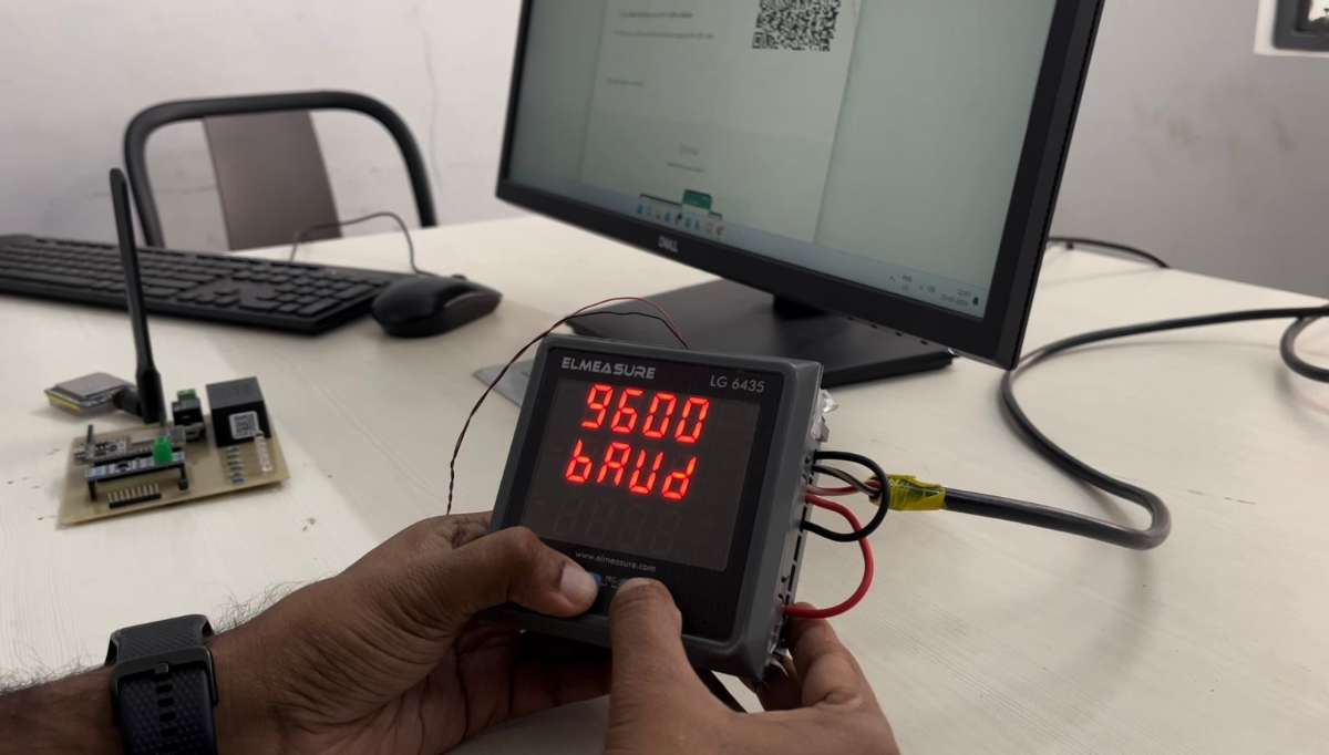
Product Images
.jpeg)
Conclusion:
Both the "Smart Energy Meter Monitoring System" and the "Energy Meter Monitoring System" offer significant benefits, including real-time data tracking, improved energy efficiency, remote monitoring, and early fault detection. They contribute to better energy management and sustainable practices. By combining these features with secure access and user-configurable settings, these systems provide a comprehensive solution for modern energy monitoring needs. The Smart Energy Meter Monitoring System goes a step further with advanced features like high current load control, reliable MODBUS RTU communication, robust power conversion, scalability to multiple meters, and cloud services using AWS. Efficient, easy, and always connected these systems are your go-to for smarter energy management.