
OVERVIEW:
In a future where batteries play a major role , battery management will be crucial for overall efficiency and sustainability. Our project focuses on monitoring the parameters of the battery so that we can optimise its performance and extend its lifespan. By closely monitoring the battery's health and charging habits, we aim to ensure it operates at peak efficiency while minimizing environmental impact.
MONITORING BATTERY PARAMETERS:
We are monitoring the 3 major parameters of the battery which includes voltage , temperature and current flow. To monitor the temperature, we use the NTC thermistor from where data is sent to the microcontroller.
int Vo = analogRead(A2); // Read the analog value from pin A2
float logRt = log(10000.0 * ((4095.0 / Vo - 1)));
float T = 1.0 / (A + B * logRt + C * logRt * logRt * logRt);
float Tc = T - 273.15; // Convert from Kelvin to Celsius
To monitor the voltage we are using a voltage divider (using the voltage divider formula) the calculations are given below:
int value = analogRead(voltage_sense);
vout = (value * 3.3 ) / 4096.0;
vin = vout * (R1 + R2) / R2;
To monitor the current , the voltage input from the battery can be used to calculate the current . the calculations are given below:
int value = analogRead(A0);
float vout = (value * 5.0) / 1024.0;
float vin = vout * r2 / (r1 + r2);
float current = vin / r2;
CIRCUIT DESIGN:
Designing the circuit current sensing , voltage sensing and temperature sensing blocks in KiCAD and intergrating the circuit design

TESTING THE CIRCUIT:
Testing a Battery Management System (BMS) circuit on a breadboard, by verifying if the individual parameters are calibrated properly.We connected the voltage circuit, current circuit, and temperature circuit separately in breadboard and tested the circuits with the help of an LCD display to monitor real-time readings. Ensure proper calibration and verify each parameter separately for accuracy.
PCB DESIGN:
creating a schematic diagram using KiCAD software, detailing all connections between the voltage, current, and temperature circuits. Carefully selecting and placing components to minimize signal interference and optimize space. Routing the traces, ensuring sufficient width for power lines and proper spacing to prevent short circuits.Adding appropriate pads for surface-mount or through-hole components and incorporating mounting holes for the PCB. Designating areas for power supply and ground planes to enhance stability. Once the layout is complete, running design rule checks (DRC) to identify and correct any potential issues. Finally, generating Gerber files for manufacturing.

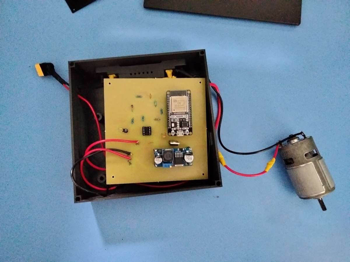
COMPONENTS ASSEMBLY:
Placing the appropriate components in the PCB board and soldering the components properly.Mounting the PCB board in the box and soldering the wires for the motor and the battery in the Pcb board
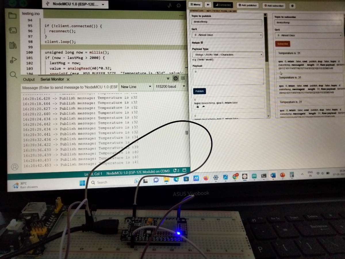
SENDING DATA THROUGH MQTT PROTOCOL:
Further We are using the MQTT protocol to transfer data to a cloud platform. MQTT (Message Queuing Telemetry Transport) is a lightweight messaging protocol ideal for IoT applications. It operates on a publish-subscribe model, enabling efficient data exchange between devices. First, we will create a topic in the MQTT publisher and publish data to this topic.Next, we will create the same topic in the MQTT subscriber to receive the published data.
We will then configure MIT App Inventor to act as an MQTT client by adding the MQTT extension and subscribing to the same topic to receive and display the data within the app. Designing the app interface by creating blocks in the MIT app inventor to display the incoming sensor data in real-time. This setup allows real-time data transfer and display between the ESP32 and the MIT App Inventor app.
