


An artificial arm is to replace the human arm that has been lost. Though from the research point of view, designing an exact resemblance of a human arm is a difficult task, day-to-day the importance of it leads to improvement.
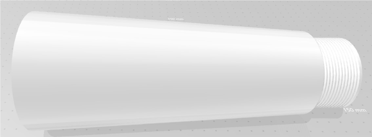
This project is basically designed using 3D design software like Solid Works, NXCAD that are available. In this project, we have used Solid Works software which is freely available and can be easily be installed, and can is also simple to design the required structure by anyone. The following are the designs of each part of the arm and these are printed using a 3D printer.
A robot is a machine that replaces human efforts, though it may not resemble the mankind in appearance and functioning. Nowadays, their use in daily life has a great extension which can even perform functions similar to the human like arm.
HOUSEHOLD ROBOTS:
A robot would be developed that would take over most household tasks and that the vast majority of housewives would want to be entirely relieved of the daily work in the household, such as cleaning the bathroom, scrubbing floors, cleaning the oven, doing laundry, washing dishes, dusting and sweeping, and making beds. Despite a multitude of investments, the multifunctional home robot is still not within reach. During the last ten years, the first robots have made their entry into the household, but they are all ‘one-trick ponies’ or monomaniacal: specialized machines that can only perform one task.
HAND GESTURE CONTROLLED ROBOTS:
The robot's development will depend upon the movements made by strategies for Hand. In recent years, robotics is a demanding technology in the field of science. To increase the use of robots where conditions are not certain such as security operations, robots can be made such that it will follow the instruction of the human operator & execute the task. This project describes the gesture control robot which can be controlled by your normal hand gesture. The accelerometer controls the movement of the car. Accelerometers are used to measure the angular displacement of human hand motion. It consists of mainly two parts, one is the transmitter part and another is the receiver part. The transmitter will transmit the signal according to the position of an accelerometer attached to your hand and the receiver will receive the signal and make the robot move in its respective direction. Here, the program is designed by using Arduino. Any robot can be controlled by using Arduino, and not only we can control it, but we can use it to do minimum of 256 different functions
BLOCK DIAGRAM:

The block diagram shows all the major components that are required for the implementation of the artificial arm. Here we have used the HC-05 module which is interfaced with a microcontroller connected. The power supply is required for the HC-05 Bluetooth module. Arduino and servos is 5V.Driving of 5V from Arduino as input to servo motors is not preferable, as the power supply drops. The microcontroller will generate the control signals to operate the five servo motors of the robotic arm.
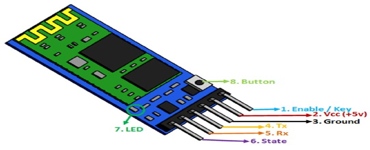
BLUETOOTH MODULE:
- The HC-05 is a very cool module which can add two-way (full-duplex) wireless functionality to your projects.
- You can use this module to communicate between two microcontrollers like Arduino or communicate with any device with Bluetooth functionality like a Phone or Laptop.
- There are many android applications that are already available which makes this process a lot easier.
- SPP (Serial Port Protocol) module, designed for transparent wireless serial connection setup.
- Serial port Bluetooth module is fully qualified Bluetooth V2. 0+EDR (Enhanced Data Rate) 3Mbps Modulation with complete 2.4GHz radio transceiver and baseband.
- The module communicates with the help of USART at 9600 baud rate hence it is easy to interface with any microcontroller that supports USART.
- We can also configure the default values of the module by using the command mode.
- So if you looking for a Wireless module that could transfer data from your computer or mobile phone to microcontroller or vice versa then this module might be the right choice for you.
However do not expect this module to transfer multimedia like photos or songs; you might have to look into the CSR8645 module for that
MODES OF HC-05:
The HC-05 has two operating modes, one is the Data mode in which it can send and receive data from other Bluetooth devices and the other is the AT Command mode where the default device settings can be changed. We can operate the device in either of these two modes by using the key pin as explained in the pin description.
It is very easy to pair the HC-05 module with microcontrollers because it operates using the Serial Port Protocol (SPP). Simply power the module with +5V and connect the Rx pin of the module to the Tx of MCU and Tx pin of module to Rx of MCU as shown in the figure below
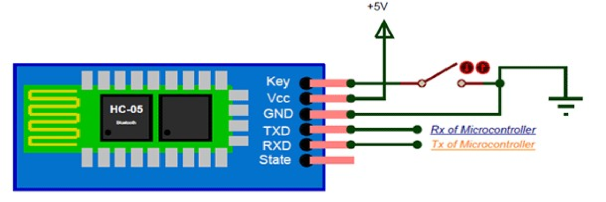
During power up the key pin can be grounded to enter into Command mode, if left free it will by default enter into the data mode. As soon as the module is powered you should be able to discover the Bluetooth device as “HC-05” then connect with it using the default password 1234 and start communicating with it. The name password and other default parameters can be changed by entering into the command mode.
TRAINING OF BLUETOOTH MODULE:
1. AT Mode:
a) Way 1:
Step 1: Input low level to PIN34.
Step 2: Supply power to the module.
Step 3: Input high level to the PIN34. Then the module will enter to AT mode. The baud rate is as same as the communication time, such as 9600 etc.
b) Way 2:
Step 1: Connect PIN34 to the power supply PIN.
Step 2: Supply power to module (the PIN34 is also supplied with high level since the PIN34 is connected with power supply PIN). Then the module will enter to AT module. But at this time, the baud rate is 38400. In this way, user should change the baud rate at the AT mode, if they forget the communication baud rate.
2. Communication Mode:
Step 1: Input low level to PIN34.
Step 2: Supply power to the module. Then the module will enter to communication mode. It can be used for pairing.
3. Master Mode:
Step 1: Input high level to PIO11.
Step 2: Supply power to the module. And the module will enter to the order-response work mode.
Step 3: Set the parameters of the super terminal or the other serial tools (baud rate: 38400, data bit:8, stop bit:1, no parity bit, no Flow Control)
Step 4: Sent the characters “AT+ROLE=1\r\n” through serial, then receive the characters “OK\r\n”. Here, “\r\n” is the CRLF.
Step 5: Input low level to PIO, and supply power to the module again. Then this module will become master role and search the other module (slave role) automatically to build the connection.
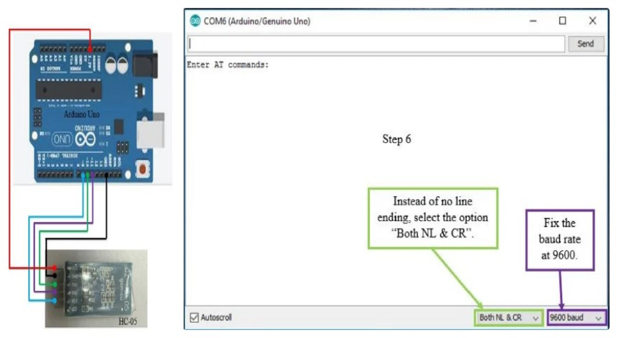
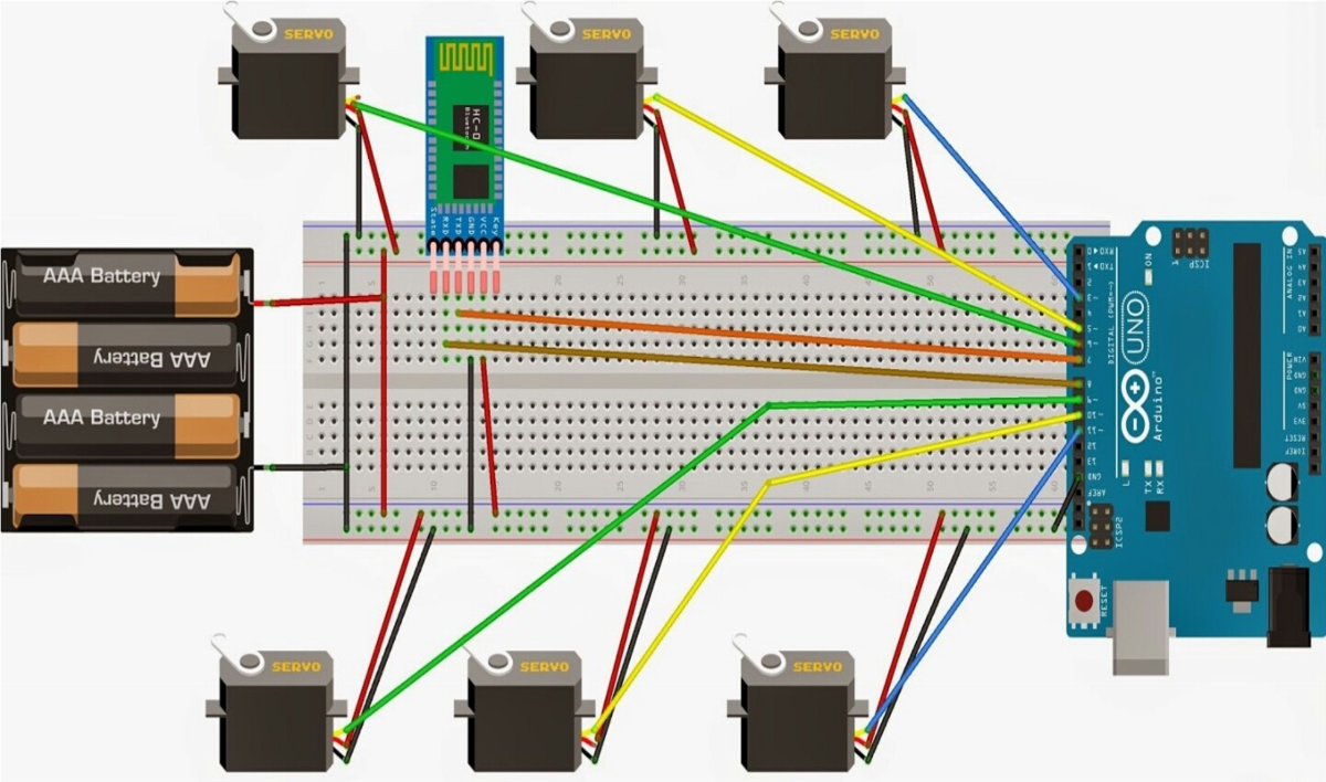
1.Firstly, connect the components as shown in the diagram above. From the diagram, the VCC of HC-05 is connected to the 3.3v of the Arduino Uno. If the VCC of HC-05 is connected directly to 5v of Arduino Uno, there is a high possibility that HC-05 will be damaged.
2.Next, before connecting the Arduino board to the USB cable, remove the VCC wire from the HC-05. Only after you have removed the VCC wire, connect the USB to the Arduino board.
3.Download the sample source code (file name: at mode) attached below and upload it into your Arduino board.
4.After the uploading process is complete, then reconnect the VCC wire back to your HC-05.
5.Now you will see the led on the HC-05 Bluetooth module is blinking for every 2 seconds interval. This indicates that the Bluetooth module has entered at mode.
6.To give at commands, open your serial monitor. For about 1 second, a sentence saying "enter at commands:" will pop up. But before that, remember to change "no line ending" to "both nl & cr" and also fix the baud rate at 9600. You can refer to the diagram attached above.
7.To see whether everything is okay or not, enter "at" and send. An "ok" will pop up on the serial monitor and this implies that no problems occur.
Slave configuration:
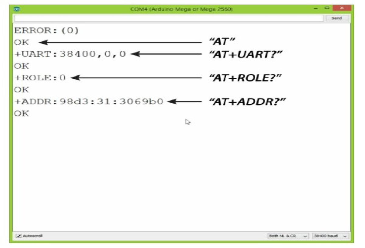
- The required at commands to set the configuration
- AT+RMAAD(to clear any paired devices)
- AT+ROLE=0 (to set it as slave)
- AT+ADDR (to get the address of this HC-05, remember to jot the address down as it will be used during master configuration)
- AT+UART=38400,0,0 (to fix the baud rate at 38400)
- If the commands entered are replied with "ok" then it indicates that the settings mentioned have been customized. You may also try out other at commands such as how to change the name, the password, and so on. A full set of at commands is attached below and kindly download it for your own use. Note that the password for both master and slave must be the same otherwise pairing will not be done.
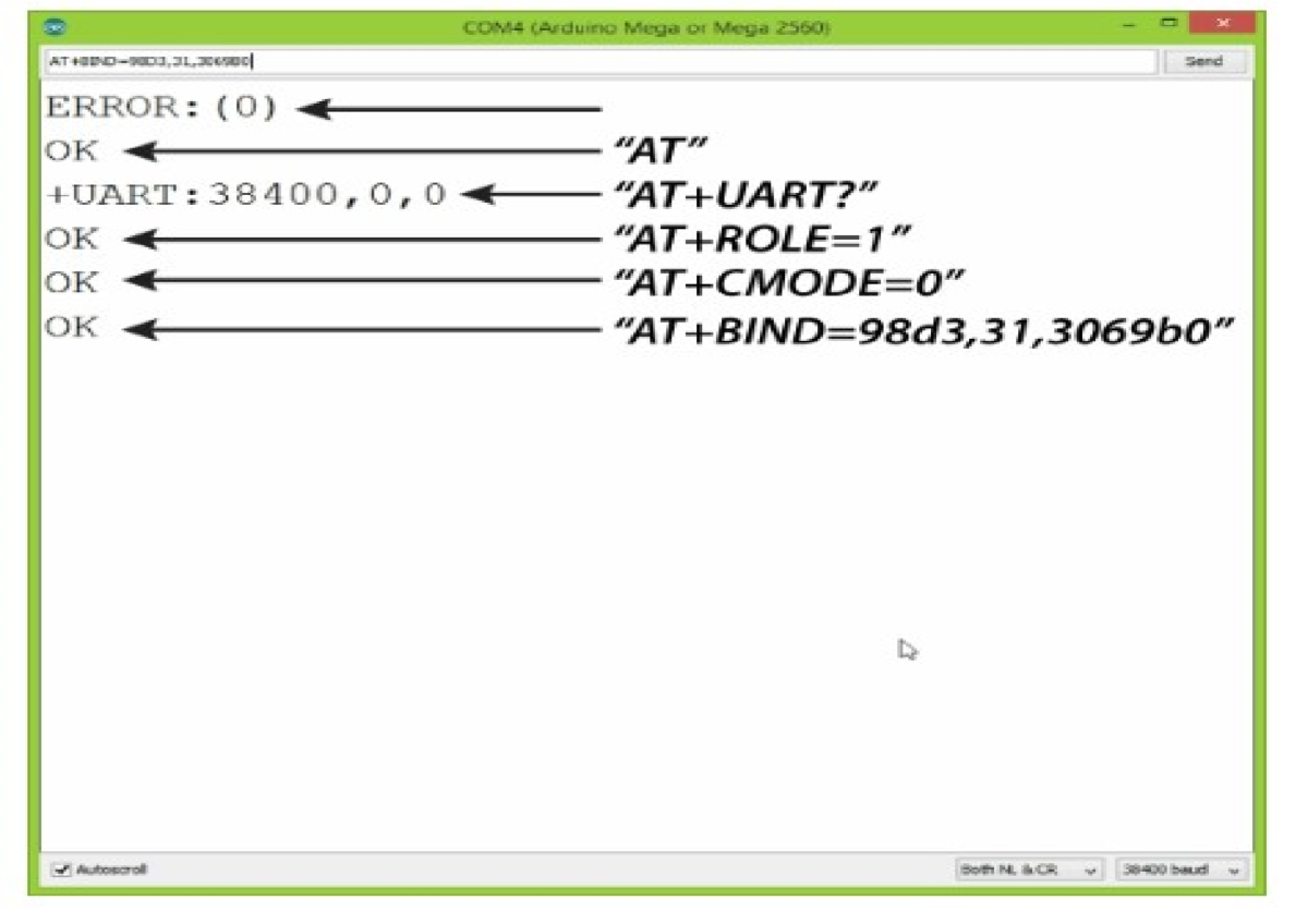
Master configuration:
- The required at commands to set the configuration:
- AT+RMAAD (to clear any paired devices)
- AT+ROLE=1 (to set it as master)
- AT+CMODE=0 (to connect the module to the specified Bluetooth address and this
Bluetooth address can be specified by the binding command)
- AT+BIND=xxxx,xx,xxxxxx (now, type AT+BIND=98d3,34,906554 obviously with your respective address to the slave. Note the commas instead of colons given by the slave module.
- AT+UART=38400,0,0 (to fix the baud rate at 38400)
TRAINING STATUS:
Applications:
- Wireless communication between two microcontrollers
- Communicate with Laptop, Desktops and mobile phones
- Data Logging application
- Consumer applications
- Wireless Robots
- Home Automation
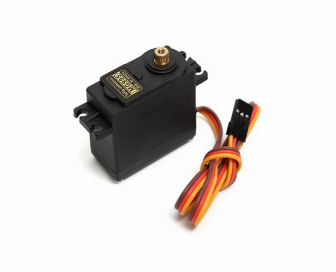
SERVO MOTOR:
CONNECTIONS:
WORKING:
- Robot arms work with an outside user or by performing predetermined commands.
- Nowadays, the most developed field of robot arms in every field is the industry and medicine sector.
- Designed and realized in the project, the robot arm has the ability to move in 2 directions with 5 servo motors.
While doing this, robotic arm control is provided by connecting to the android application via Bluetooth module connected to Arduino uno microcontroller.
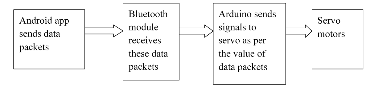
BLOCK DIAGRAM:
- Connect Bluetooth module to android app - When you power up your Hardware the Bluetooth module will become visible. So open the application and click on find nearby devices. Select HC-05. Once it shows connected you are good to go.
- The android app sends data packets to the Bluetooth module.
- The Bluetooth module sends this data packet to Arduino Uno through Serial Communication.
- Arduino Uno is programmed to generate control signal for the servo motor depending upon the value of the data packet.
- The block diagram gives a clear explanation regarding the working of Bluetooth module and interfacing it with Arduino.
- The interfacing of Arduino, a Bluetooth module and servo motor is done.
- This project has overcome the limitations of number of commands that can be stored and performed.
- It also has overcome the limitation of accessing only one person's voice.
- Since the commands are need not be trained, it is easy for the user and also there exist no interference effect of external noise.
- It can perform the task faster than the voice module since it need not check the trained voice command as there's no need of training the commands.