
Every time I go out and lock my door using traditional lock, I feel so outdated. I wanted to replace it with something interesting and modern, in terms of technology and uses. Something that can provide "better security" and "ease of use". So, I decided to build "An RFID Based Door Lock/Entry System." A system that can be used in every house or premises. It can normally be replaced with your traditional lock and has RFID tags as key to unlock the door.
I named it "Captiosus System" ( Captiosus is the Latin word, that means smart in English ).
This system has an RFID scanner where you scan your RFID tag (Only registered RFID tags in the system database) and it opens the door. This system has a alarm system also for the person who is trying to enter with non-registered RFIDs. It has email notification for all the entries (Permitted and denied entries)
This system uses best combination of hardware and software and can be considered as a best use of modern technology to modernize our way of living. You are connected to your security all the time.
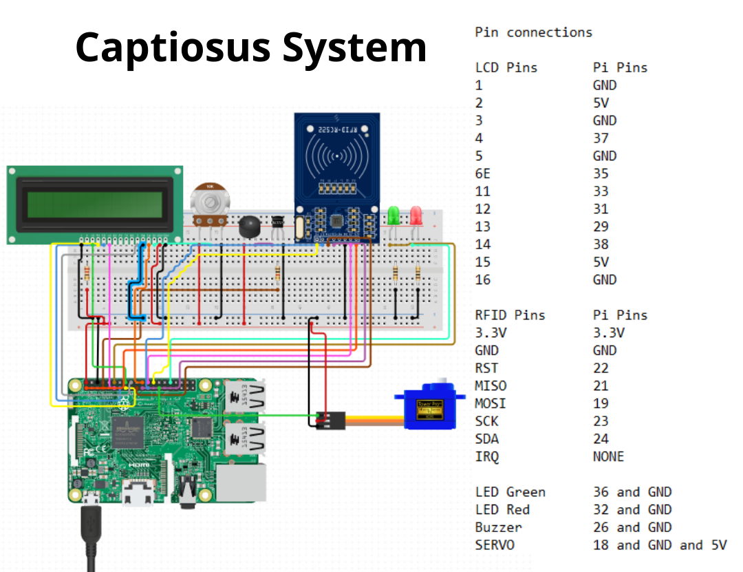
All the components are connected as per the diagram. Some additional/ supportive components are connected with the main components also.
Pin connections are done on basis of these given information.
---------------------------
LCD Pins Pi Pins
1 GND
2 5V
3 GND
4 37
5 GND
6 35
11 33
12 31
13 29
14 38
15 5V
16 GND
----------------------------
RFID Pins Pi Pins
3.3V 3.3V
GND GND
RST 22
MISO 21
MOSI 19
SCK 23
SDA 24
IRQ NONE
-------------------------
LED Green Pi pins
Vcc 36
GND GND
(A resistor is also added between Vcc of LED and Pin 36 of Raspberry Pi)
-------------------------
LED Red Pi pins
Vcc 32
GND GND
(A resistor is also added between Vcc of LED and Pin 32 of Raspberry Pi)
-------------------------
Buzzer Pi pins
Vcc 26
GND GND
-------------------------
SERVO Pi pins
Signal 18
GND GND
Vcc 5V
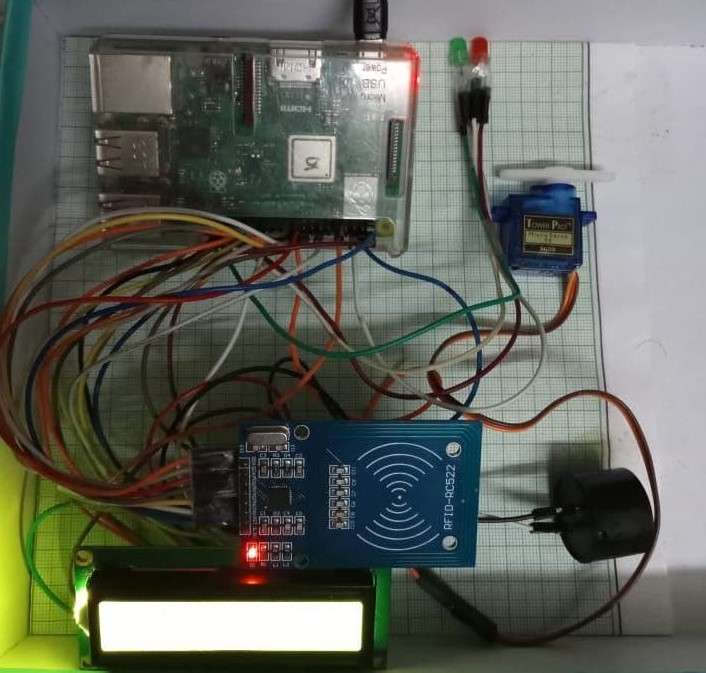
RFID Scanner, Buzzer, LEDs, Motor and Display is connected to Raspberry Pi as per given pin details - Raspberry Pi is connected to power supply - User scans his card and system calls the function based on the permission and denial of entry.