
Welcome, fellow makers and tech enthusiasts! Today, I’m thrilled to unveil my latest endeavor in the realm of Home Automation. We’re all familiar with the concept: the ability to control household appliances—such as lights, fans, and various gadgets—right from our smartphones, thanks to the power of the internet. While there’s no shortage of YouTube tutorials showcasing these projects, many of them involve significant alterations to the home’s electrical wiring. The drawback? If the central microcontroller unit (MCU) responsible for managing these connections goes down for any reason, your home could plunge into darkness.
That’s where my modified prototype comes in. By harnessing the simplicity of a ‘2 Way Switch Connection’ paired with a feedback module, I’ve developed a solution that sidesteps this potential pitfall. Here’s how it works: the feedback system continually monitors the status of each appliance—whether it’s ON or OFF—and communicates this information to the server. This approach ensures that even if the main automation system encounters a hiccup, your home remains operational and responsive.
Features of the System
- Global Control: Appliances can be controlled from anywhere in the world via the internet.
- Manual Operation: Appliances can also be controlled with manual switches without altering the electrical connections for improved reliability.
- RF Remote Control: The entire system can be operated using a 433MHz RF remote.
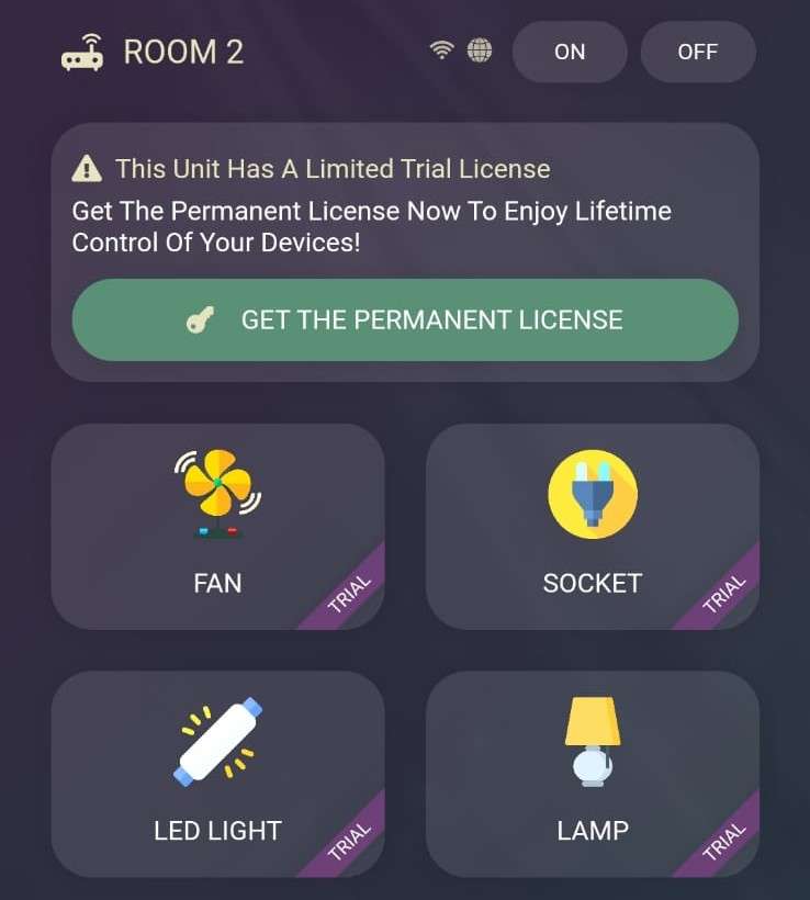
- Real-Time Monitoring: The status of each appliance can be viewed on the CADIO mobile application.
- Customizable System: CADIO provides AI-based code generation, allowing easy customization and modification of the system according to individual needs.
- Efficiency: The system features low current consumption and minimal maintenance costs once installed.
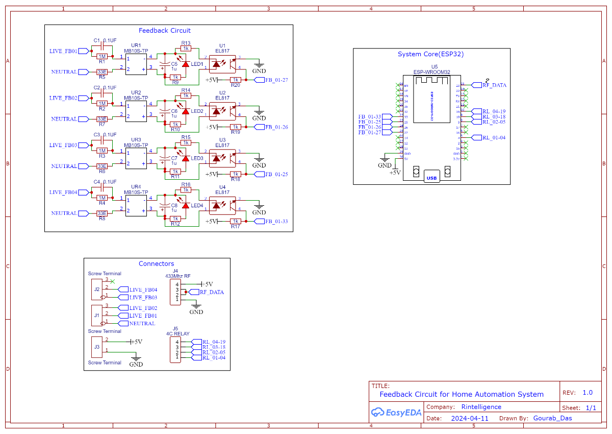
Circuit Diagram
Theory & Working of the Circuit
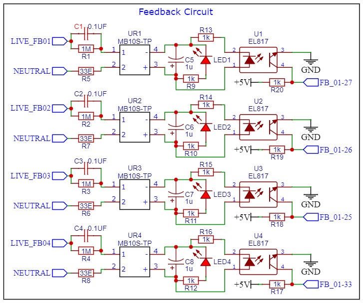
In this section, we’ve designed a compact and efficient transformer-less power supply for each relay to enable real-time feedback on the server and as well as on the CADIO Mobile Application. We utilize the dropper capacitor method, using a 0.1uF 400V Capacitor to reduce the 220V AC input to around 65V. A 1MΩ bleeder Resistor is connected in parallel with the dropper capacitor to safely discharge it when the system is turned off. To protect against voltage and current spikes, we include a 33Ω ½W Protection Resistor in series with the circuit.
The reduced AC voltage is then rectified by an MB10s Bridge Rectifier (SMD) to convert it from AC to DC. Post-rectification, a 10uF 63V Capacitor smooths out the DC supply. We also added a 5mm Red LED for visual indication of the power supply status. The supply voltage is then fed into an PC817 Optocoupler, which isolates the power supply from the ESP32 Microcontroller. Additionally, we integrated a 433MHz RF Receiver to facilitate wireless communication and control which is beneficial for elderly individuals who may not be accustomed to using smartphones. back signaling is managed by a common 5V power supply used across the board, ensuring reliable communication and control.
Additional Information
- The CADIO Platform offers server usage for our IoT application at a nominal fee of ₹790/- (including GST) per device (1 ESP32 = 1 device). This is a one-time charge, granting lifetime access to the platform with that device. Our system supports 4 channels with 4 feedback mechanisms, and with modifications, it can be extended to 10 channels with 10 feedback systems.
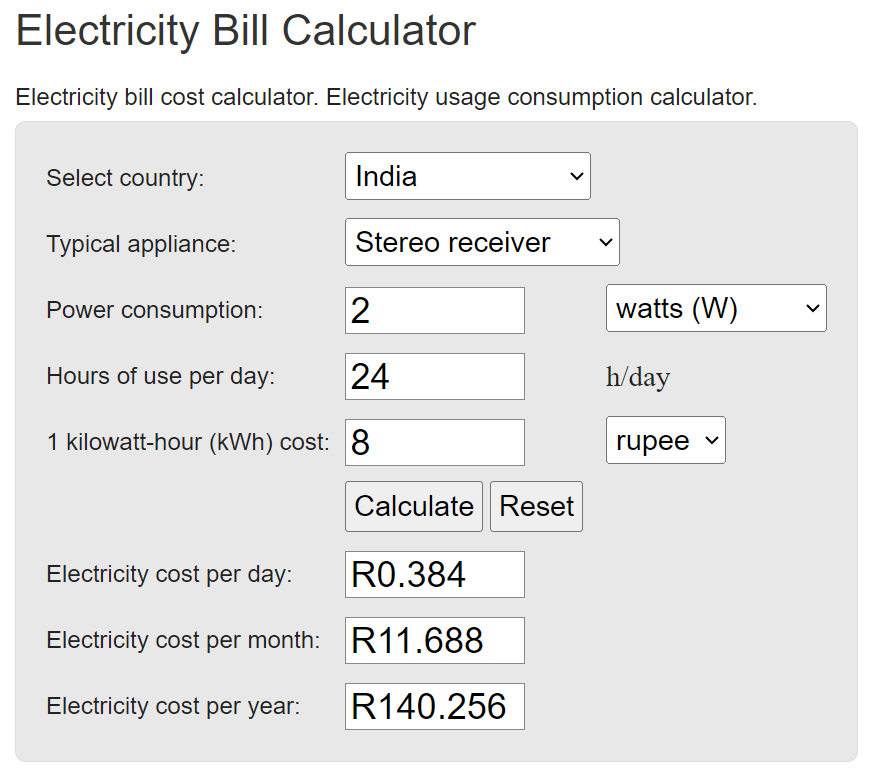
- Since this system will be operating 24/7, power consumption is a crucial consideration. During our testing, we found that the entire system, including 4 fully energized relays, the ESP32, and the RF Receiver, consumes approximately 0.40A (400mA) at full load. This equates to around 2W of power usage.
- The impact on your electricity bill is minimal. For comparison, this system consumes less power than a typical stereo receiver, which is one of the least power-consuming devices in a household. While the cost of 1kWh varies by location, you can be assured that the additional cost will be negligible. For a precise estimate, you can use an online electricity bill calculator tailored to your local rates.
Images of the Prototype
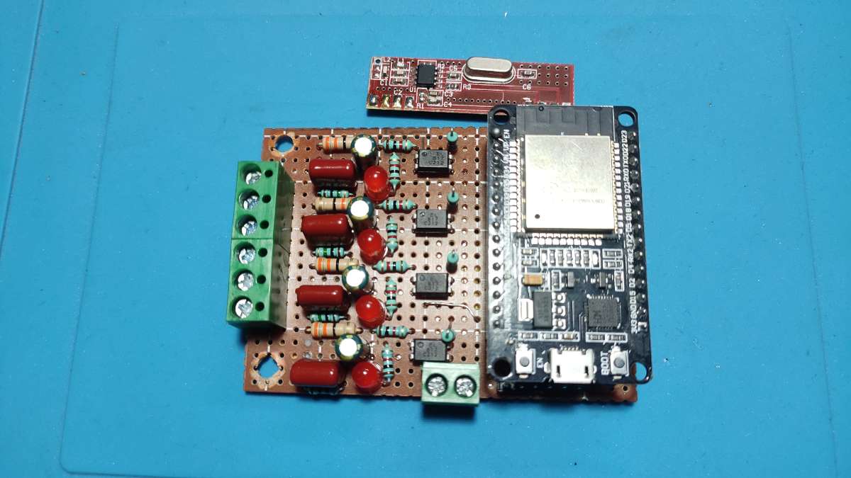
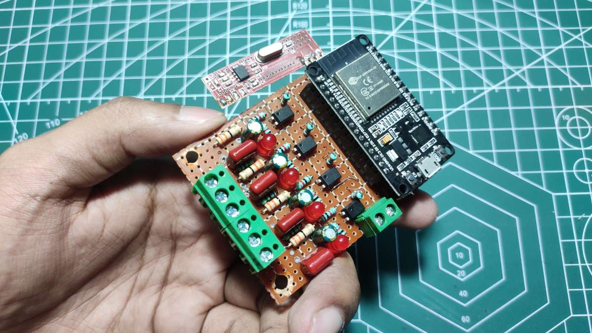
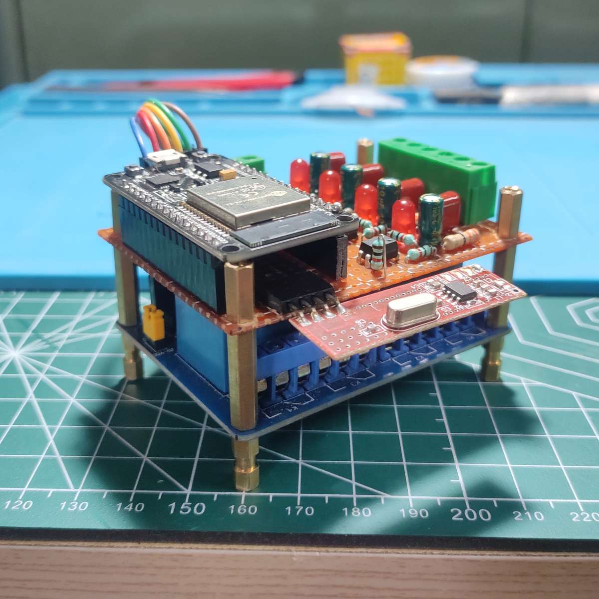
Top View of the PCB
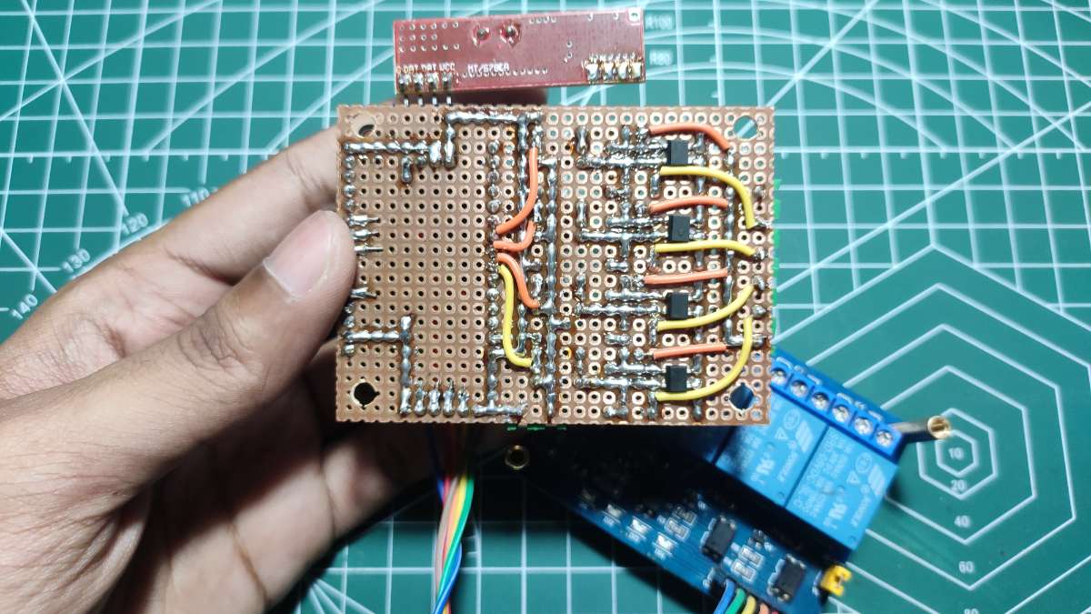
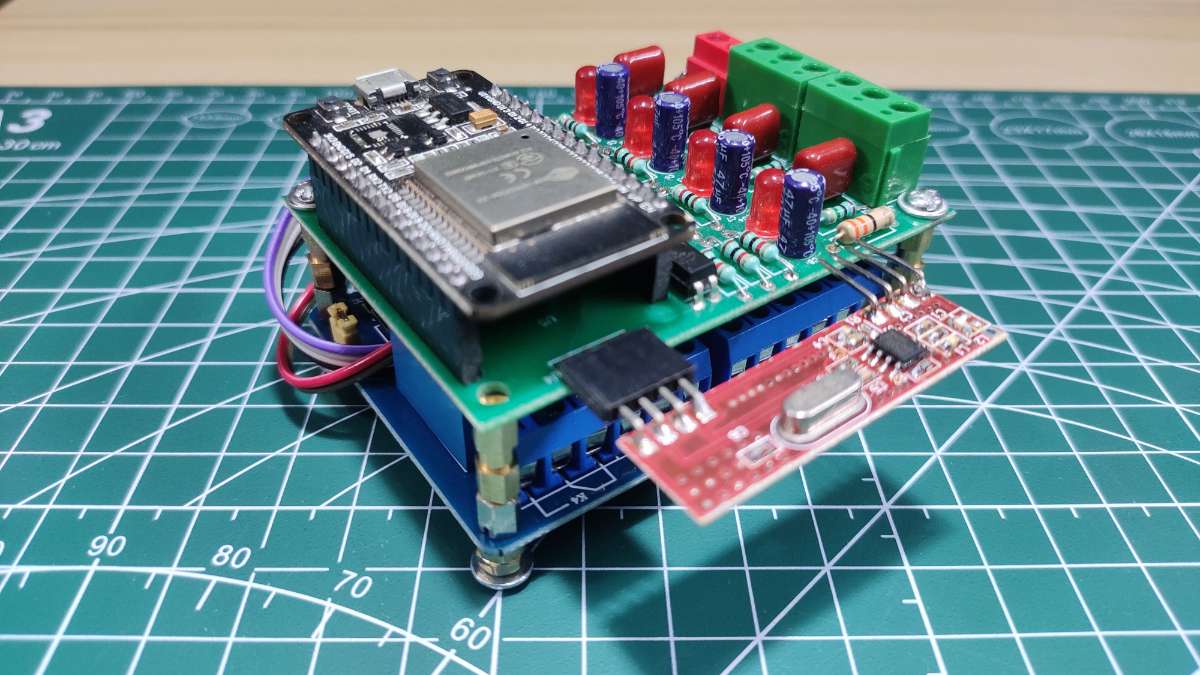
Bottom view of the PCB
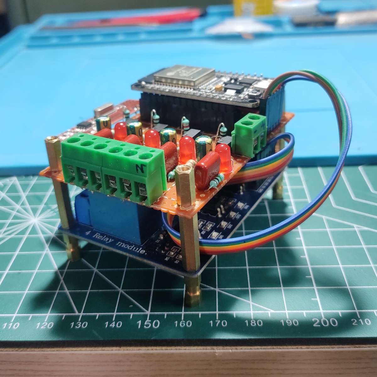
Side View of the PCB
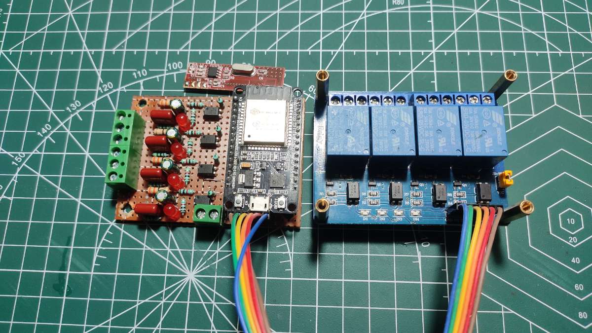
Full Setup with the 4 Channel Relay Module
The prototype is currently built on a Veroboard, which, while effective, is a challenging and intricate process. To simplify the assembly, you can design a PCB for this system. This will save significant time and effort, as you'll only need to solder the necessary components. Details of the PCB design, including the layout, component placement, and wiring schematics, are provided below to assist you in creating your own streamlined and efficient home automation system.
Schematics
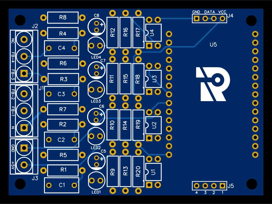
PCB Layout Images
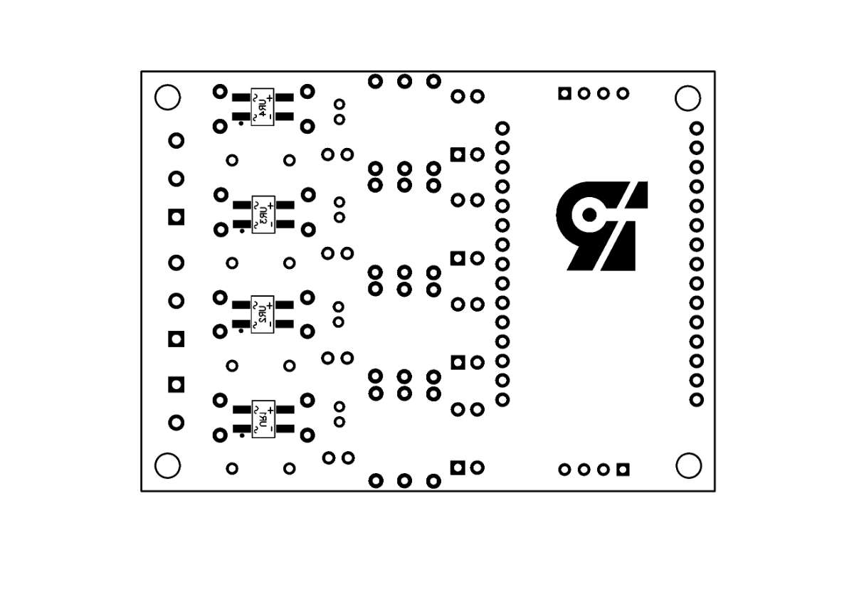
Top View PCB Layout without Connection
Top View PCB Layout with Connection
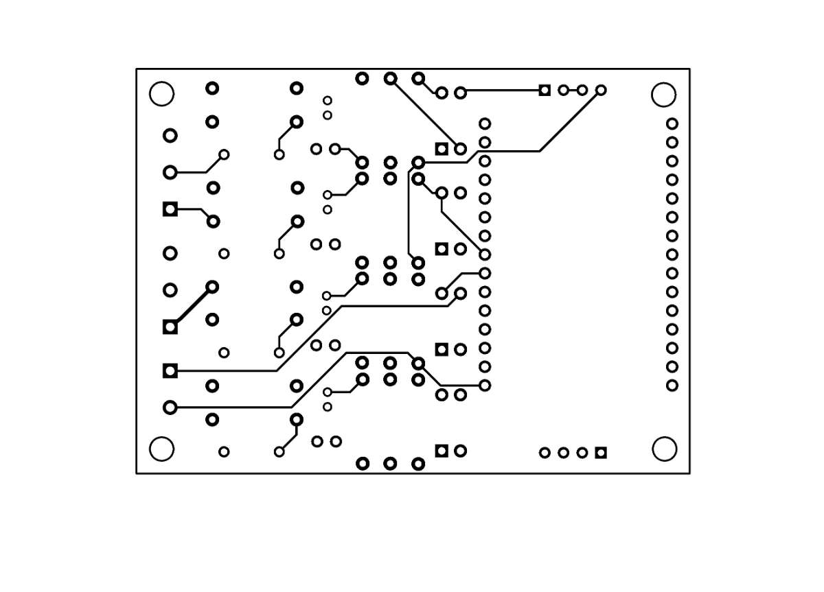
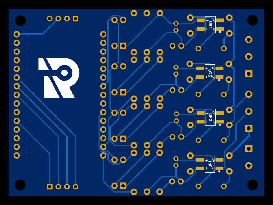
Bottom View PCB Layout without Connections
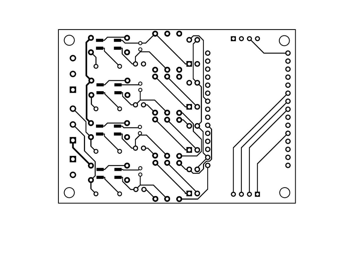
Bottom View PCB Layout with Connections
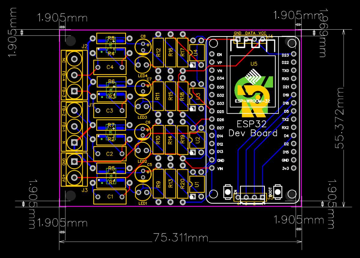
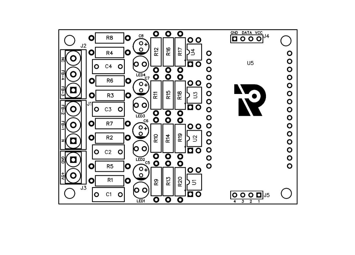
Colored PCB Layout with Dimensions
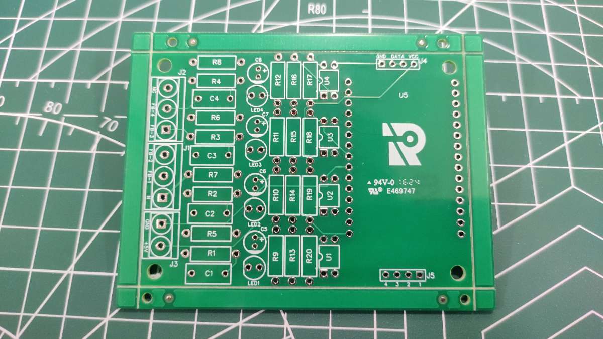
PCB Photo View
Top View
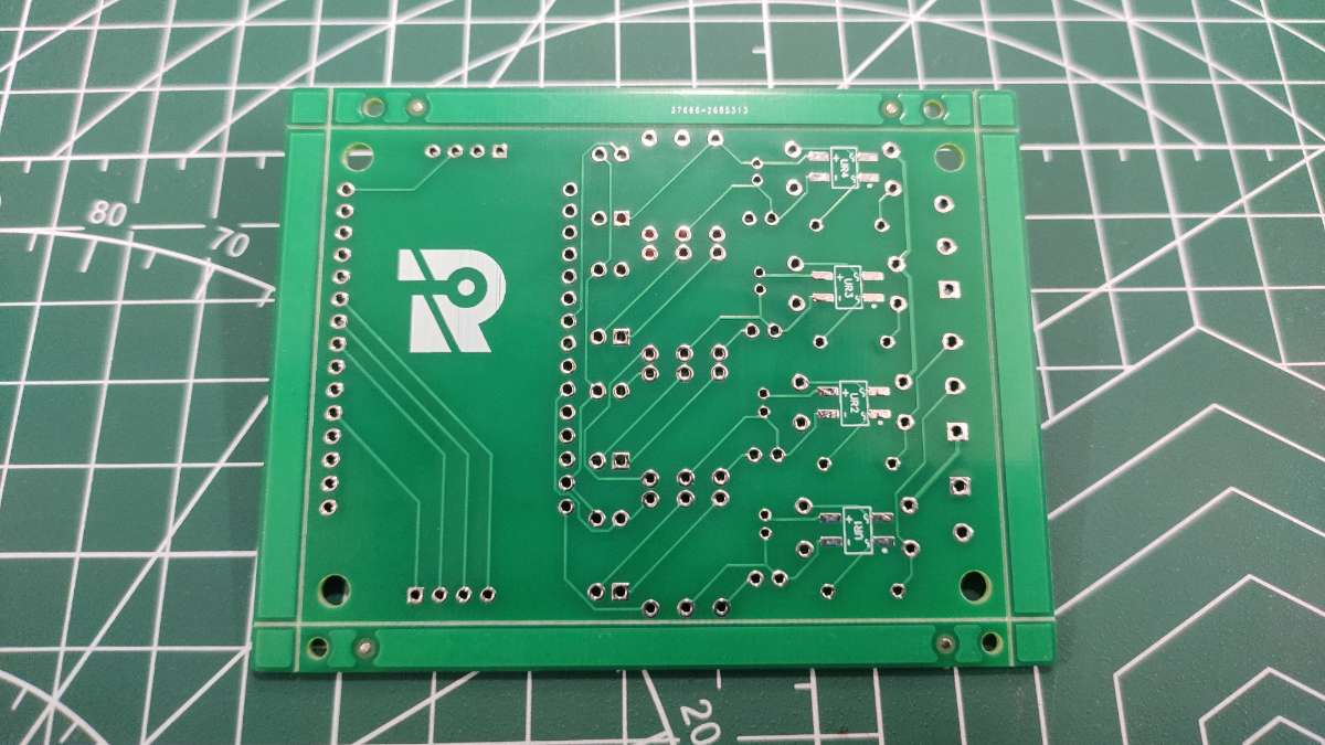
Bottom View
After fabrication, the PCB turned out excellently. I ordered it from NextPCB in Shenzhen, China, and was impressed by the high quality and affordable pricing. The PCBs were delivered promptly, and their precise manufacturing ensured all components fit perfectly, facilitating a smooth assembly process. NextPCB's attention to detail and robust quality control made it an ideal choice for this project.
Top View of the PCB
Bottom View of the PCB
After assembling all the necessary components onto the fabricated PCB, the final product is neat and compact. This organized layout not only enhances the device's aesthetics but also ensures efficient functionality and easy handling. The high-quality fabrication and precise component placement contribute to a reliable and durable home automation system.
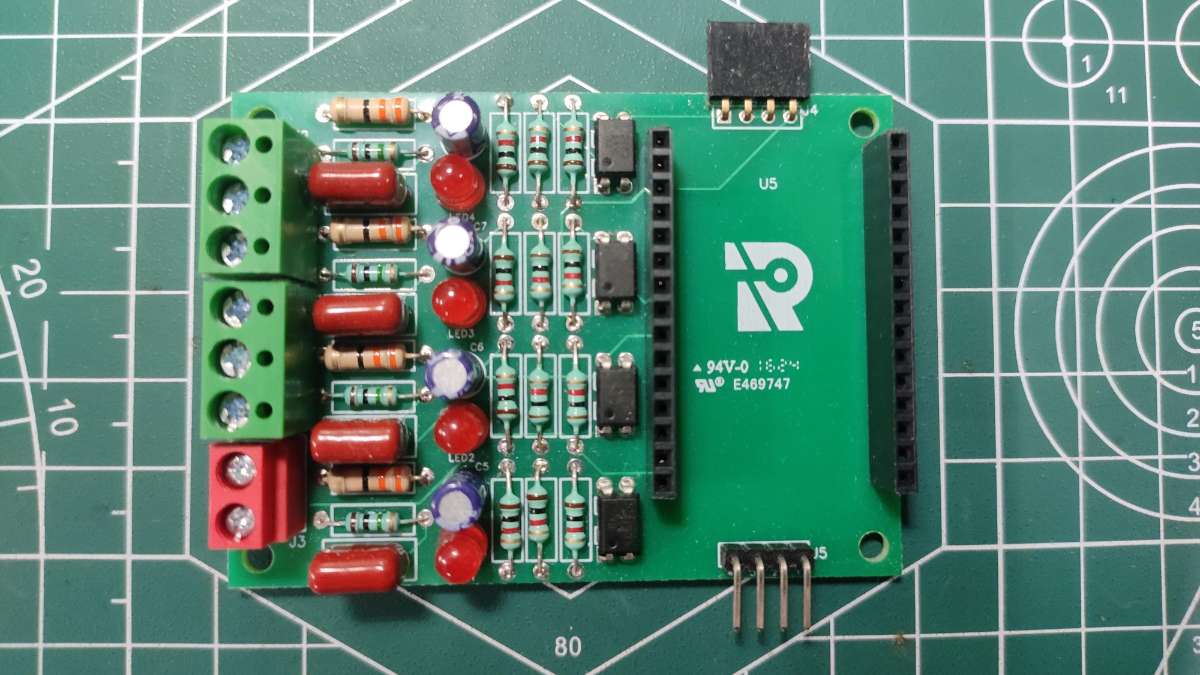
Top View of the Assembled PCB
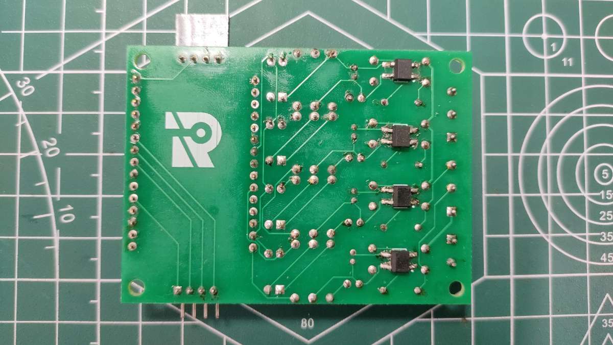
Bottom View of the Assembled PCB
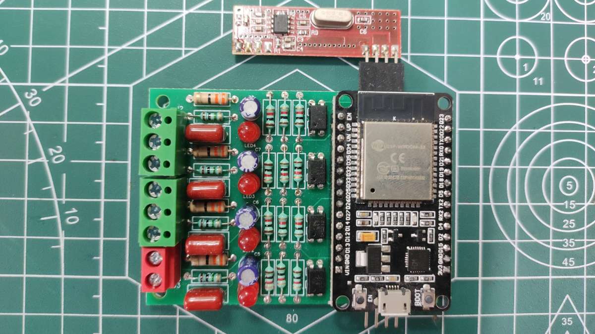
Fully Assembled PCB with ESP32 & 433MHz RF Receiver
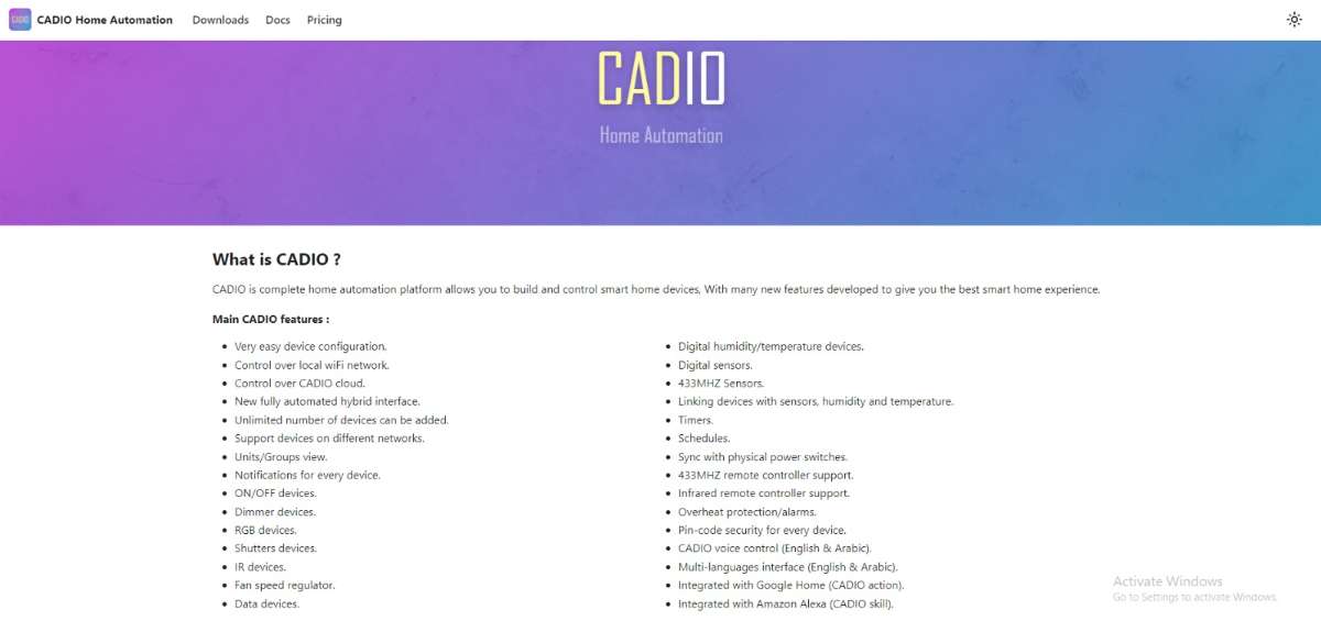
Configuration of CADIO Home Automation
- Visit the CADIO Home Automation website and select the "Downloads" option located in the top left corner of the screen.
- Next, navigate to the download center and download the ESP Flash Download Tool, along with the firmware for the board you wish to use (ESP32 and ESP8266 are supported).
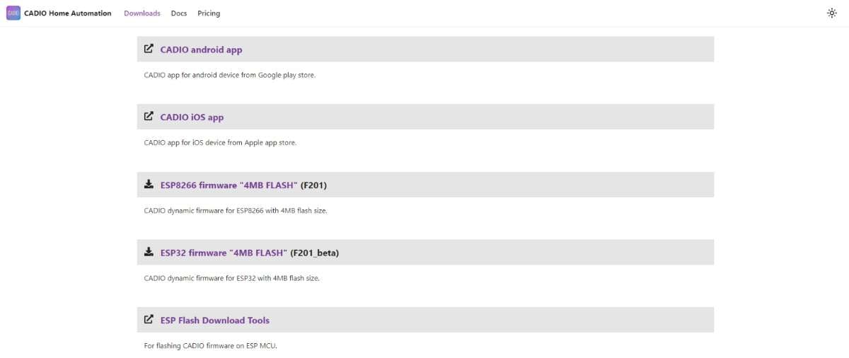
- Once downloaded, unzip and extract the two files for further use.
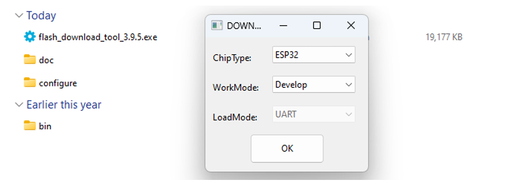
- Launch the flash download tool by executing the .exe file. A small popup window will appear on your screen. Select the board type (ESP Board) and choose the Work mode as "Develop".
- Connect the ESP board to your computer and ensure it is properly detected. Then, select the correct COM port within the flash download tool.
- Next, locate the "Erase" button at the bottom of the window and click on it to delete the existing firmware from the ESP board.
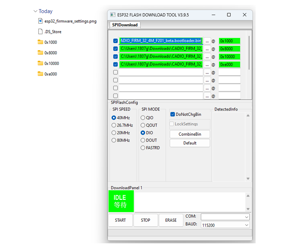
- Now, navigate to the ESP32 firmware folder and select the four firmware files. For each file, ensure that the values you input match the folder name for seamless integration.
- Tick the checkboxes next to the four firmware files (you'll notice the values turn green for each selection), then click on the "Start" button to initiate the firmware upload process.
- Congratulations! You have successfully uploaded the CADIO firmware to your ESP board. Your home automation system is now ready to be deployed and utilized for efficient control and monitoring of your appliances.
- Now, restart your ESP board and wait for a moment. You'll observe that the blue light on your ESP board begins to flash, indicating that the firmware upload process is complete and the system is ready for operation.
- Connect your smartphone to the hotspot created by the ESP board, then open the CADIO mobile application, available on both Android and iOS platforms.
- In the app, navigate to the configuration tab and click on it to access the settings.
- Your ESP board is now in configuration mode. Proceed with the configuration according to the requirements of your project. Below are the specific configuration settings for our project.
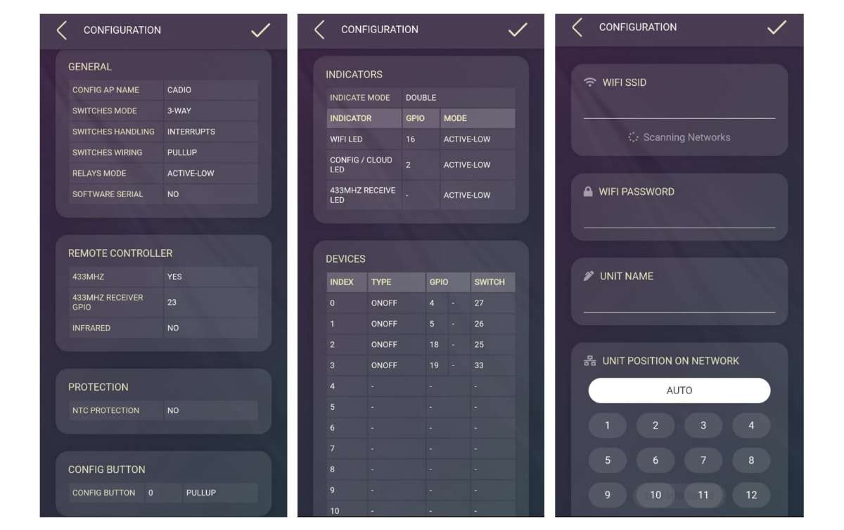
- After configuration, the ESP board will scan nearby Wi-Fi networks. Select your network from the list and provide your network credentials along with the unit name.
.jpg)
- Upon successfully completing all the steps, you'll find your board listed on the dashboard of the CADIO Mobile Application. You can further customize the icons and settings to tailor the interface to your preferences.
Detailed Configuration
- Relay_1 connected with GPIO_4 of ESP32
- Relay_2 connected with GPIO_5 of ESP32
- Relay_3 connected with GPIO_18 of ESP32
- Relay_4 connected with GPIO_19 of ESP32
- Feedback for Relay_1 is connected with GPIO_27 of ESP32
- Feedback for Relay_2 is connected with GPIO_26 of ESP32
- Feedback for Relay_3 is connected with GPIO_25 of ESP32
- Feedback for Relay_4 is connected with GPIO_33 of ESP32
- 433MHz RF Receiver is Connected with GPIO_23 of ESP32
These configurations are tailored for our 4 Channel Home Automation Project, but you can modify them to suit the specific requirements of your project. This flexibility allows you to customize the system for various applications and needs.
Setting Up the 433MHz RF Remote with the System
- Launch the CADIO mobile app on your device.
- In your project, press and hold the widget you want to add RF remote functionality to.
- At the bottom of the screen, select the "433MHz" option.
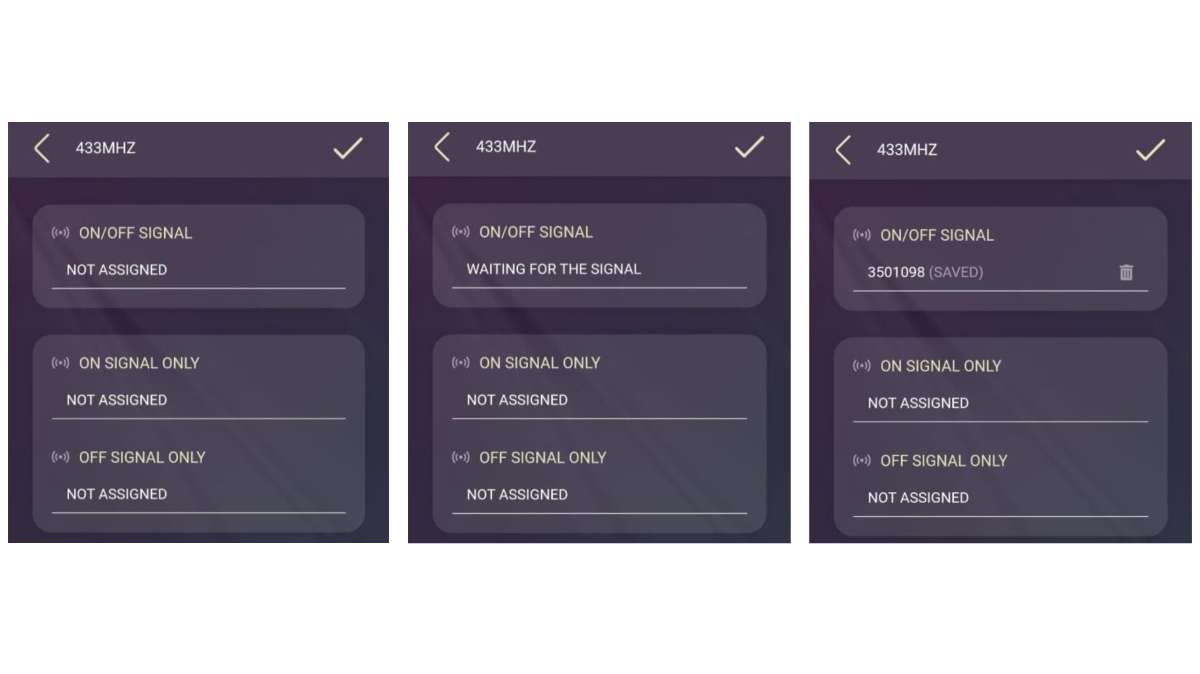
- You'll see three options: "ON/OFF Signal," "ON Signal Only," and "OFF Signal Only".
- Click "ON/OFF Signal" (initially 'Not Assigned'), and it will change to 'Waiting for the signal.'
- Press the button on your RF remote that you want to use to control this widget.
- The app will capture the signal transmitted by the button, assigning it to toggle the widget or appliance ON/OFF.
- Repeat these steps for all widgets you want to control with the RF remote, assigning a button for each.
Additional Information
The CADIO platform features AI-generated code on the backend, so no coding knowledge is required. Simply select the desired functions and types from their dropdown menu, and CADIO will handle the rest. This user-friendly approach streamlines the setup process, making home automation accessible even to those without technical expertise.
If you prefer not to configure these settings manually, I have provided the firmware in a zip format. Simply unzip the file, and during the configuration process, you'll find an "Import" option. Select the unzipped firmware file, and you're ready to go. All you need to do then is enter your WiFi credentials and device name, and your product will be operational.
How to connect with the Main Board
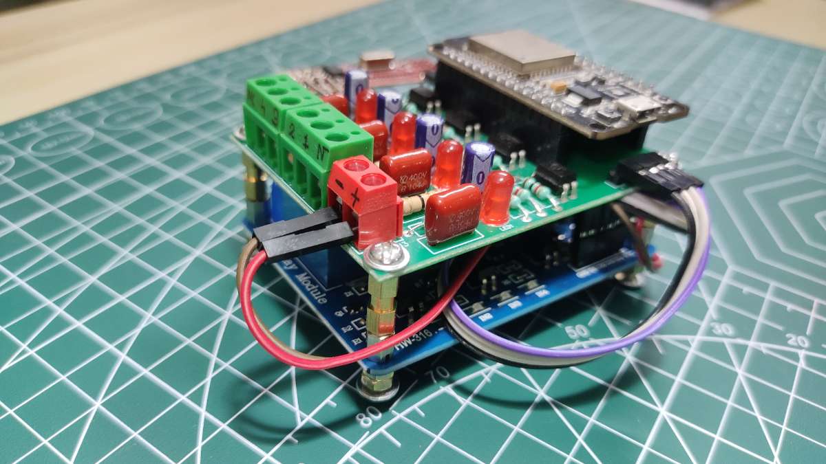
Before connecting, make sure you are familiar with the terminal configuration of the Feedback PCB. This is crucial for ensuring proper setup and functionality of your home automation system.
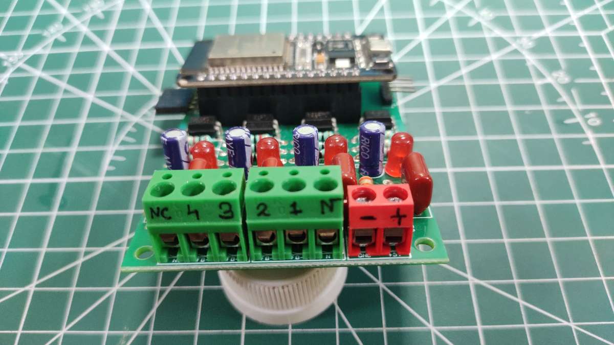
- The symbol "+" indicates: Connect the +5V source from your power supply here.
- The symbol "-" indicates: Connect the GND (ground) connection of your power supply here.
- The character "N" indicates: Connect the NEUTRAL line from the mains here.
- The character "NC" indicates: No connection (extra slot).
- The numbers "1" to "4" indicate: The Feedback Input in order.
Once you are familiar with all the terminal configurations, let's explore how to use a "2 Way Switch Connection" to integrate your Home Automation project with your main switchboard. This method allows you to control your appliances both manually and via the automation system without altering the existing electrical wiring.
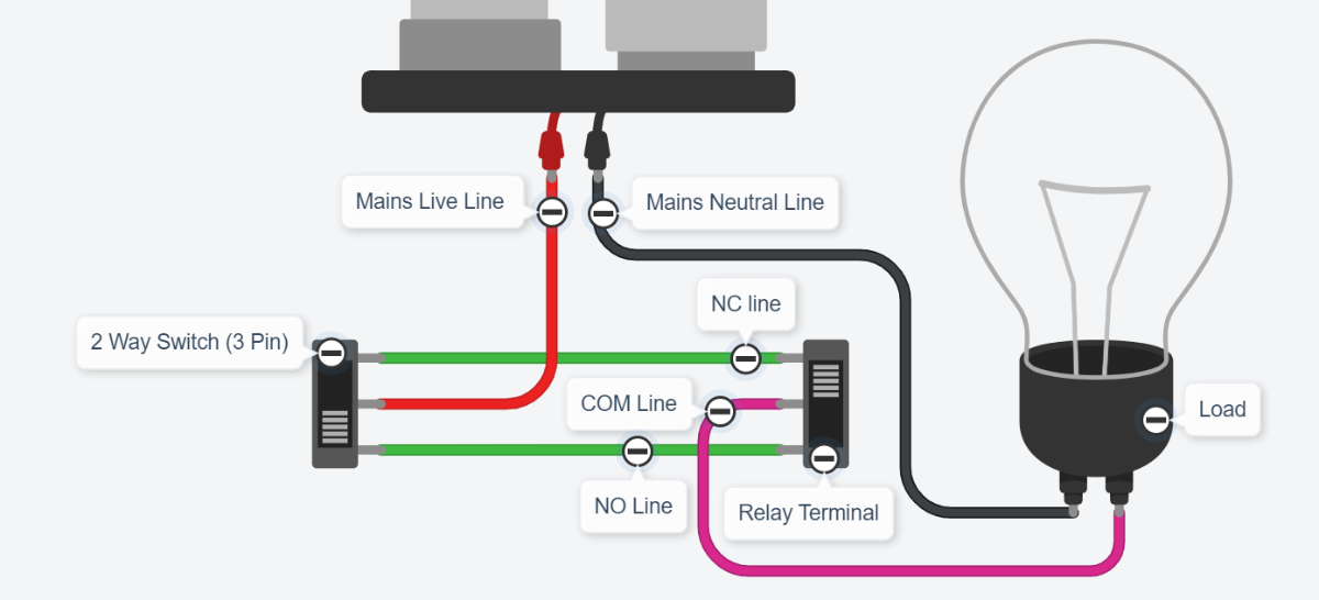
Here’s how your circuit should look:
Visual Guide: Consider the left switch as your "2 Way Switch" and the right one as the "Relay Terminal." Connect the circuit exactly as shown in the picture above.
Neutral Line Connection:
- Take one connection from the "Mains Neutral Line."
- Connect this wire to the "N" terminal on your feedback PCB.
COM Line Connection:
- Take one connection from the "COM Line."
- Connect this wire to the appropriate feedback input terminal (1 to 4) on your feedback PCB.
By following these steps and using the visual guide, you can ensure that your home automation project is correctly connected, providing both manual and automated control of your appliances.
The Final Outcome
After carefully following all the steps, your product should look neat and compact, just like this. This organized setup not only enhances the device's aesthetics but also ensures efficient functionality and easy handling.
Prototype Front View
Prototype Rear View
PCB Front View
PCB Rear View
Conclusion
In conclusion, my new approach to home automation not only simplifies the process by eliminating the need for extensive rewiring but also enhances reliability and safety through the innovative use of a 2 Way Switch Connection with a feedback module. By ensuring that each appliance's status is constantly monitored and communicated to the server, we've addressed one of the major vulnerabilities of conventional home automation systems. Now, even if the central MCU fails, your home won't be left in the dark. This system is a significant leap forward for DIY enthusiasts and tech-savvy homeowners who value both convenience and peace of mind