Always realize after leaving the bathroom at night that the light wasn't turned off? Not only does it waste electricity, but it also shortens the lifespan of the light bulb. Don’t worry, this tutorial teaches you how to make a bathroom automatic light switch: the light turns on automatically when you enter, and turns off automatically when you leave. It saves electricity and effort, and even electronics beginners can easily do it.
Materials to Prepare
The things used in this auto light system are not expensive and can be purchased in electronic markets or online stores:
- Normally open reed switch (with magnet)
- LM741 op-amp (1pc)
- CD4017 decimal counter (1pc)
- BC558 PNP transistor
- 5V relay module (with optocoupler is recommended)
- Resistor: 10KΩ ×2, 100Ω, 820Ω one each
- Mini breadboard, some Dupont cables
- 5V power supply (USB) Power supply module is also OK
- Light bulb (LED lights, low voltage lights can be, or relay control 220V bulb)
What's the deal with the reed switch?
A reed switch is actually a magnetized switch, and this time we're using a normally open type:
The switch closes when the magnet is close to it, and breaks when the magnet leaves.
How to install it? It is very simple:
- Reed switch is glued to the door frame
- Magnet is glued to the door
- The door is closed, the magnet is close to the reed switch → conductive
- The door is open, the magnet is far away → disconnect
This can be used to determine whether the door is open or not.
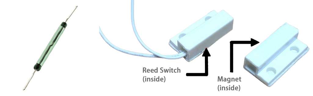
reed switch structure and housing
The reed switch is built into the plastic case and used in conjunction with a magnet to realize the magnetic induction switching function of the door.
How does the circuit work?
The whole control logic is divided into three segments:
- Reed switch detects the door status
- LM741 + CD4017 make logic judgment
- Relay controls the on and off of the light
.jpg)
DIY Automatic Light Control Circuit Diagram
The complete circuit structure of the whole system is shown above: the door magnetic induction module on the left, the signal processing circuit in the center, and the load control module on the right.
How exactly do you link it? See below:
- The LM741 is used as a comparator that outputs a clean high/low signal when the gate state changes (reed switch is open/closed)
- This signal is connected to the clock input pin of the CD4017, and every time it is triggered, the output of the CD4017 “steps back”
- We connect the reset pin, for example, at the output of pin Q1 immediately reset, we can make two states alternately: the first light on, the second light off
- The output of the CD4017 is connected to a 5V relay module to control the switch of your light bulb
In this way, each time you open the door (or close the door), the state of the lamp will be reversed:
bright → off → bright → off...
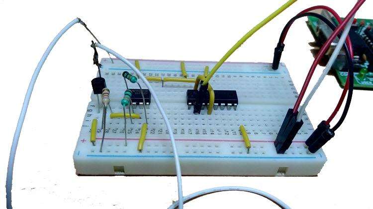
breadboard connection LM741 CD4017
Shown above is the actual breadboard wiring diagram, so please compare the wiring carefully.
Installation steps
- Reed switch + magnet installed on the door, remember to adjust the position, so that when the door is closed, it can be tight, the door can be disconnected
- Breadboard inserted LM741 chip, do not insert the reverse, pin for reference
- Connect the resistor, BC558, to make a comparator
- The output of the comparator to the clock pin of the CD4017
- Q0 pin of the CD4017 to the input of the relay, Q1 pin back to its reset pin (pin 15)
- Light bulb connected to the output of the relay, pay attention to the voltage match
- Power on test! When the door opens, the light is on; when it opens again, the light is off!
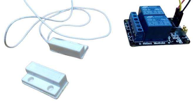
reed switch relay module
Above is the physical display diagram of reed switch and relay module for reference of actual installation.
Actual working demonstration
The scene is simulated as follows:
You open the bathroom door → the reed switch is disconnected → LM741 outputs a signal → the CD4017 trips → the relay closes → the lamp lights up
You open and close the door again when you leave → the CD4017 trips again → the relay closes → the light switches off automatically
This simple automatic light system, power saving, worry, durability, but also solved the “forget to turn off the lights” trouble.
I wish you good luck and happy DIY!